Last night and today we are in a different spot through the OFI. See Sheila's alog 78096 for the move that was made.
Overall, SR2 and SRM yaw are much closer to center in this position, however SRM pitch is farther from center. I did a quick double check of the SRM pit, and indeed this is where it wants to be.
The previous spots (with the previous SR3 alignment) are recorded in alog 77443.
| ampl [cts] of line at 31.0 Hz | A2L gain step size when minimizing | CAL-DELTAL line reduction factor | Final A2L gain | Inferred new spot position [mm] | Change from alog 77443 position | |
| SR2 P2L | 1.0 | 0.1 | 100x | -1.0 | -2.0 | 13.1 mm other side of center |
| SR2 Y2L | 1.0 | 0.1 | 100x | +0.3 | 0.6 | 9.7 mm other side of center |
| SRM P2L | 2.0 | 0.1 | 50x | -5.5 | -11.1 | 4.3 mm farther from center |
| SRM Y2L | 2.0 | 0.1 | 30x | +1.85 | 3.7 | 3.5 mm closer to center |
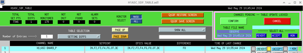
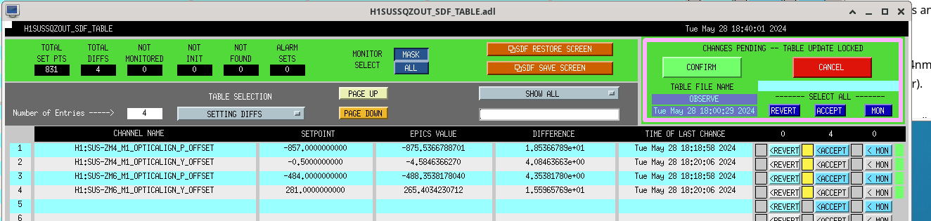
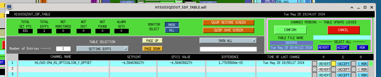
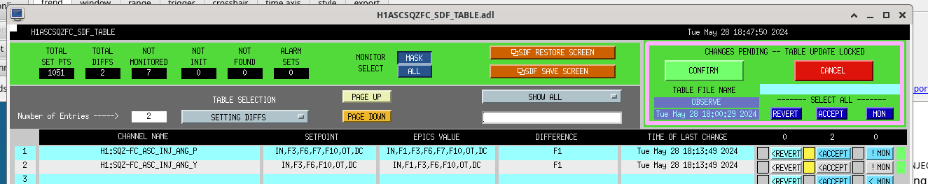
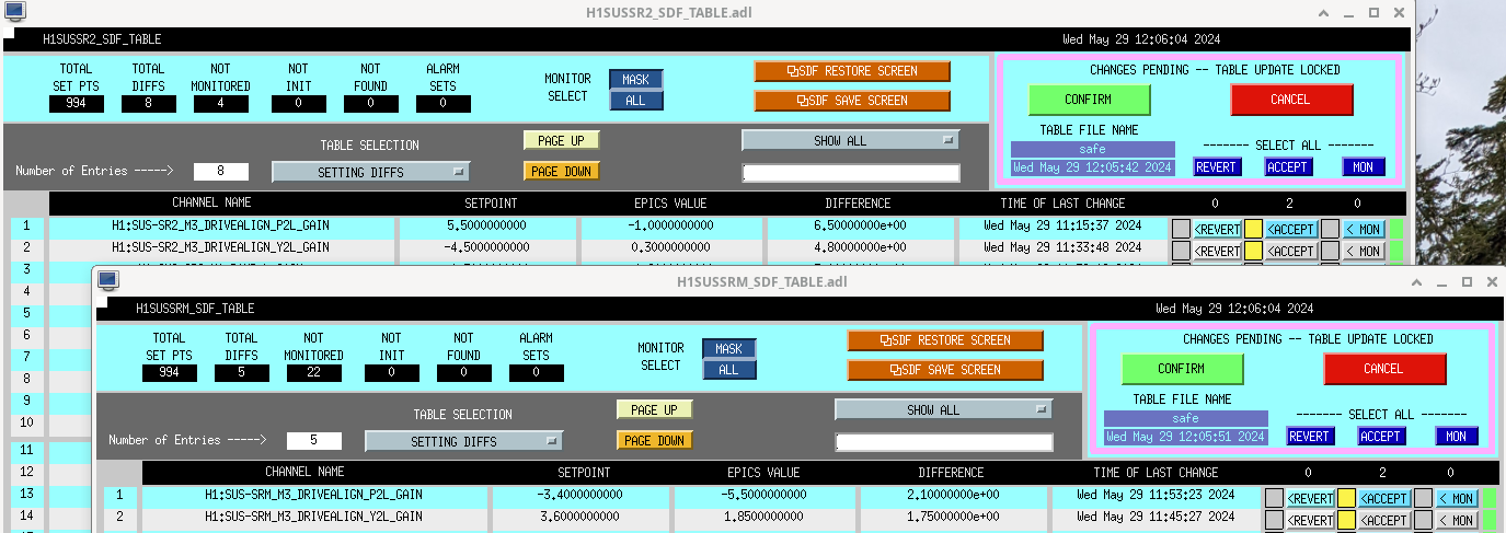
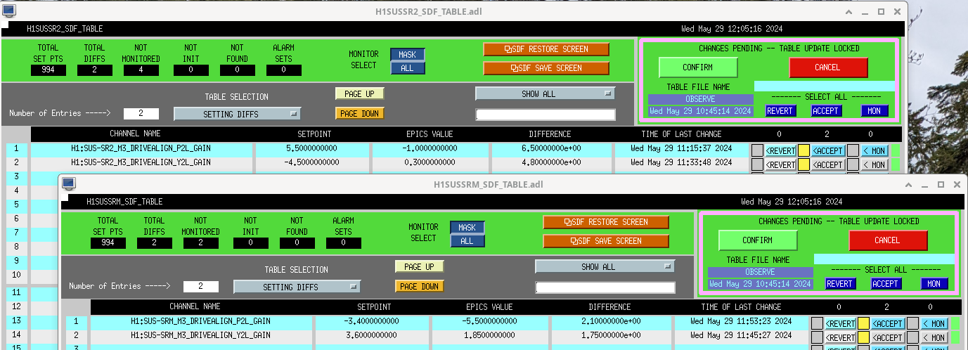
Attached are the saved SDF diffs for both Observe and Safe snap files.
Sheila and Keita have recently found and fixed sign convention errors. Please see alog 78393 for the corrected interpretation of A2L gains.
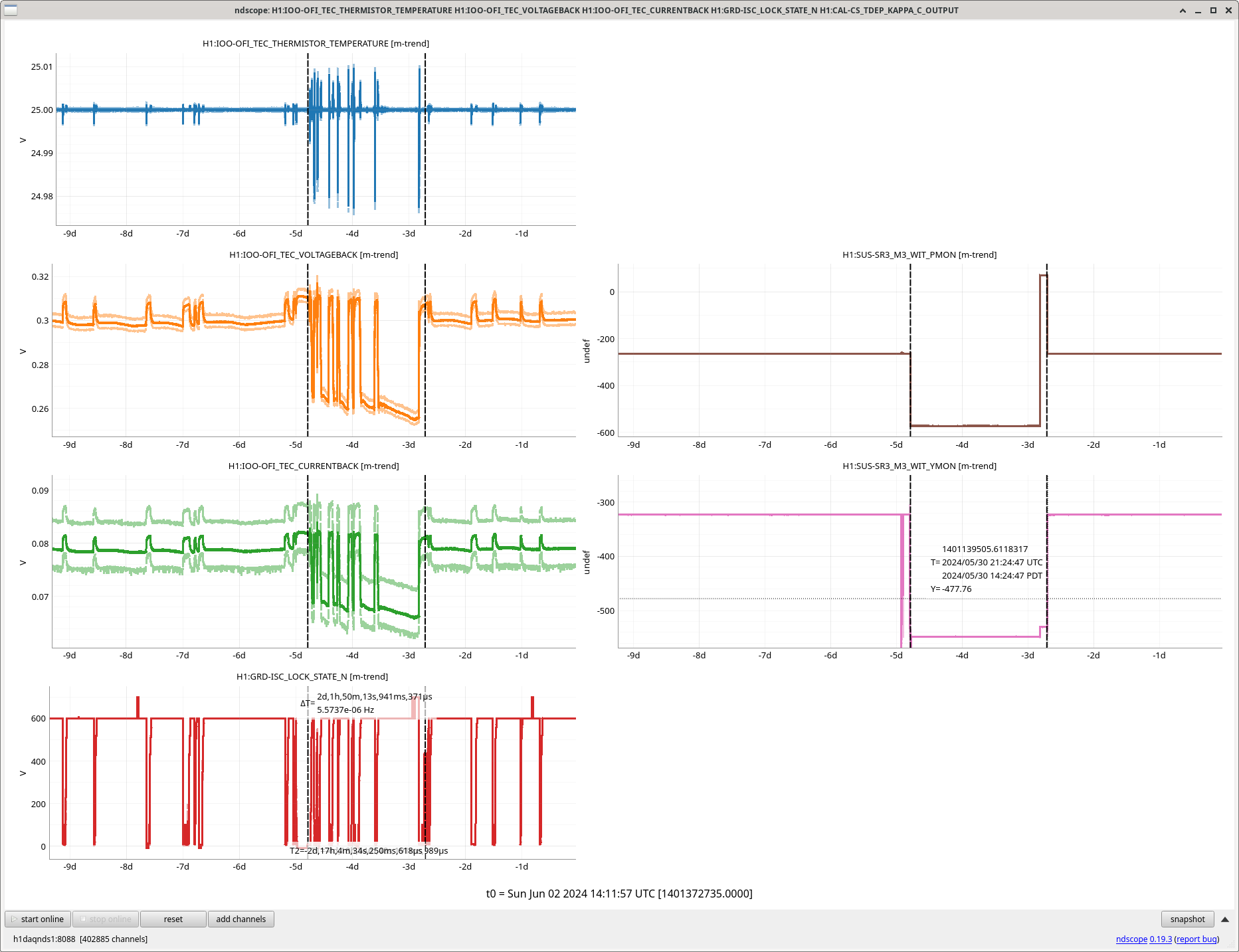
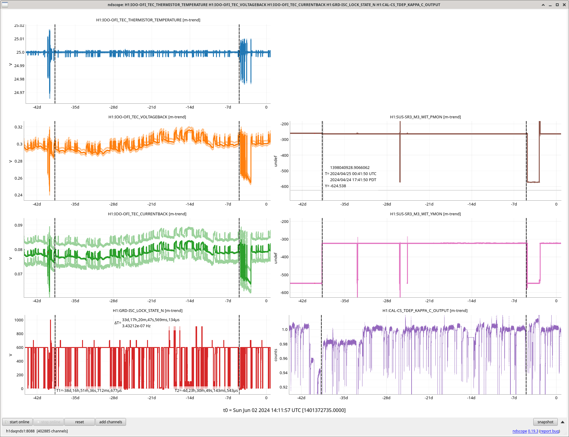
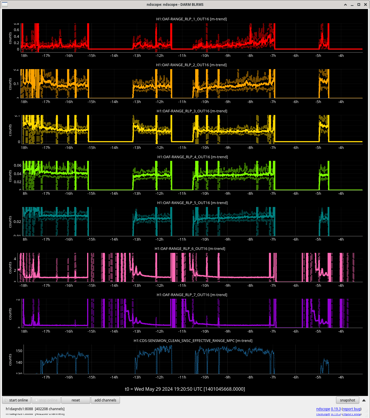
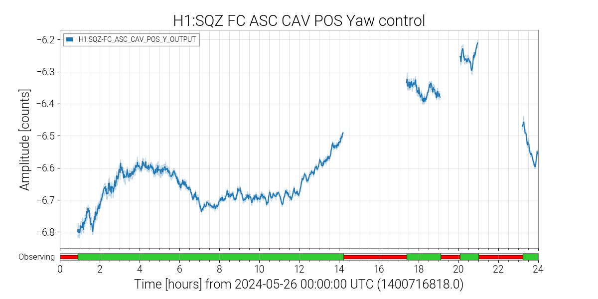
Sheila, Camilla. During this May 28th/29th SRC alignment, the OFI sees larger than usual temperature swings on locklosses and powerups. See plot attached. We saw similar larger OFI temperature swings on the re-locking attempts after our April 22nd optical gain drop before we changes alignments, shown in 78399 and second attached plot. Is the beam in this alignment hitting something in the OFI? Could be more likely the yaw alignment as that is common in both alignments with larger temperature swings.