Alex Ritzie, Ansel Neunzert
Key points
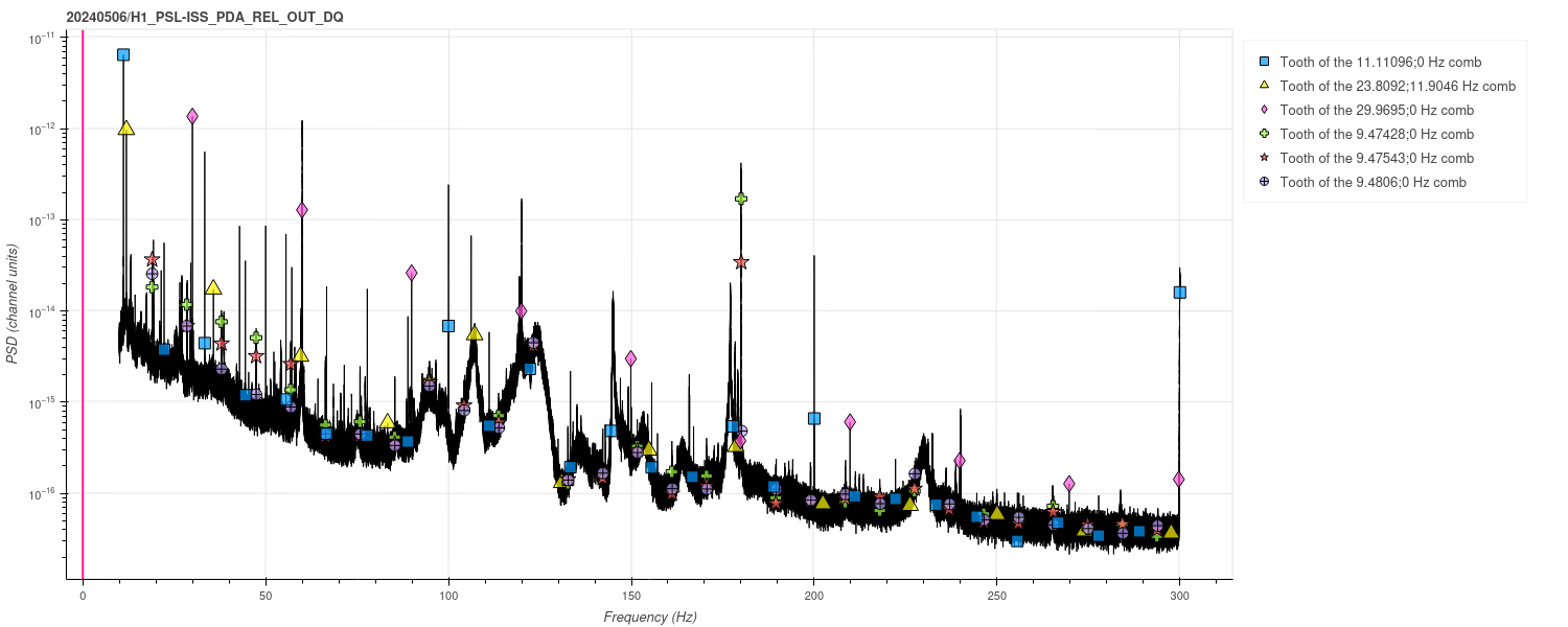
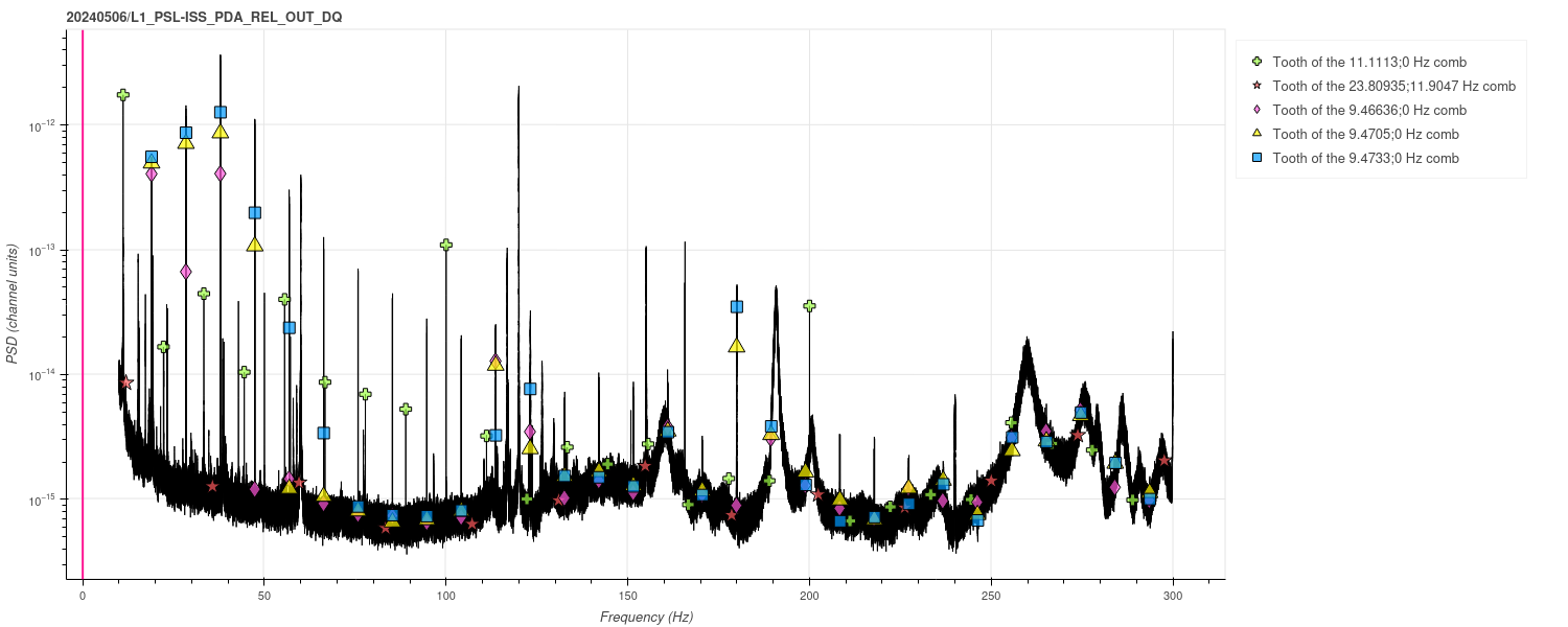
The 9.5 Hz comb triplet (LHO worst offender comb), 11.11 Hz comb, and 11.9 Hz comb, are present in {H1,L1}:PSL-ISS_PD{A,B}_REL_OUT_DQ. These combs were previously known to be common between the two sites (see LLO 70030, LLO 66036, git issue for 9.5 and 11.9 for more info). A near-30 Hz comb is also seen at LHO only.
Details
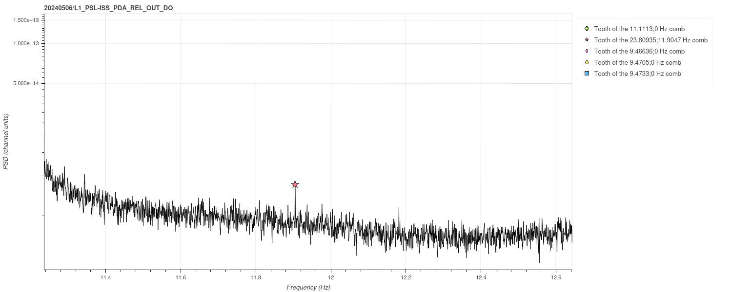
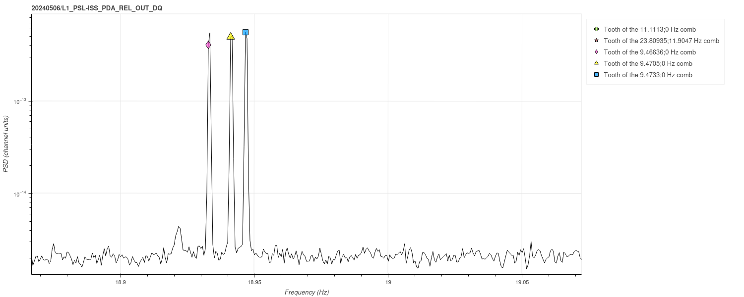
Plots of H1:PSL-ISS_PDA_REL_OUT_DQ and L1:PSL-ISS_PDA_REL_OUT_DQ are attached (figures 1 and 2). Note that the color coding differs between the two plots. The 9.5 Hz combs are much stronger at LLO than at LHO. The 11.9 Hz comb is almost not visible at LLO, but the first harmonic is faintly present (figure 3).
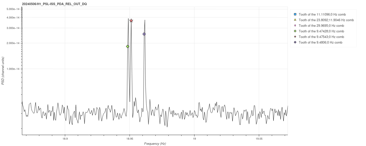
Note that the 9.5 Hz combs may not appear to line up exactly on this plot at higher frequencies, but they are known to shift around regularly and I'm just plotting the average O4a positions here. I'm confident that it's the same artifact because the characteristic triplet structure is clearly apparent at every peak (see figures 4 and 5).
Both of these plots are from May 6. This date is not special, it's just a convenient recent date with a reasonable amount of observing time, which avoids other recent comb contamination issues at LLO.
Methods & context
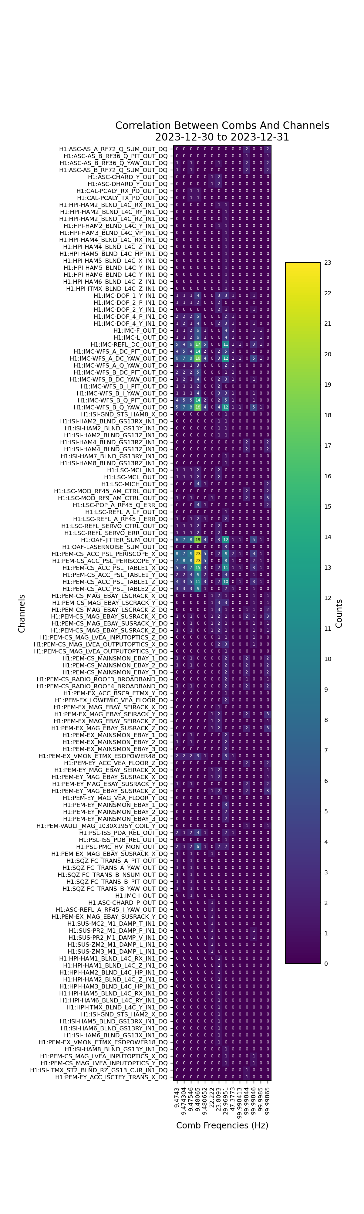
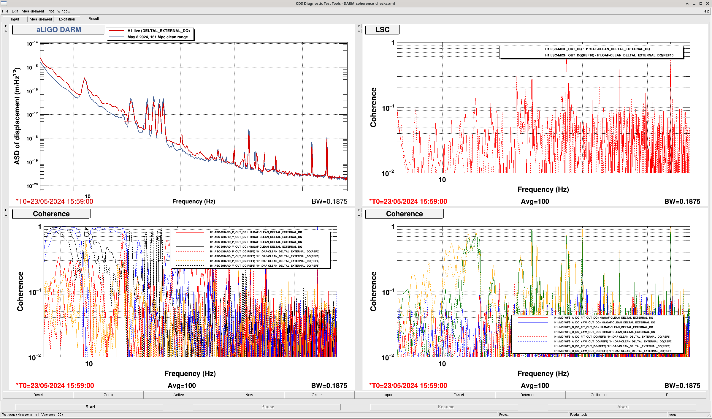
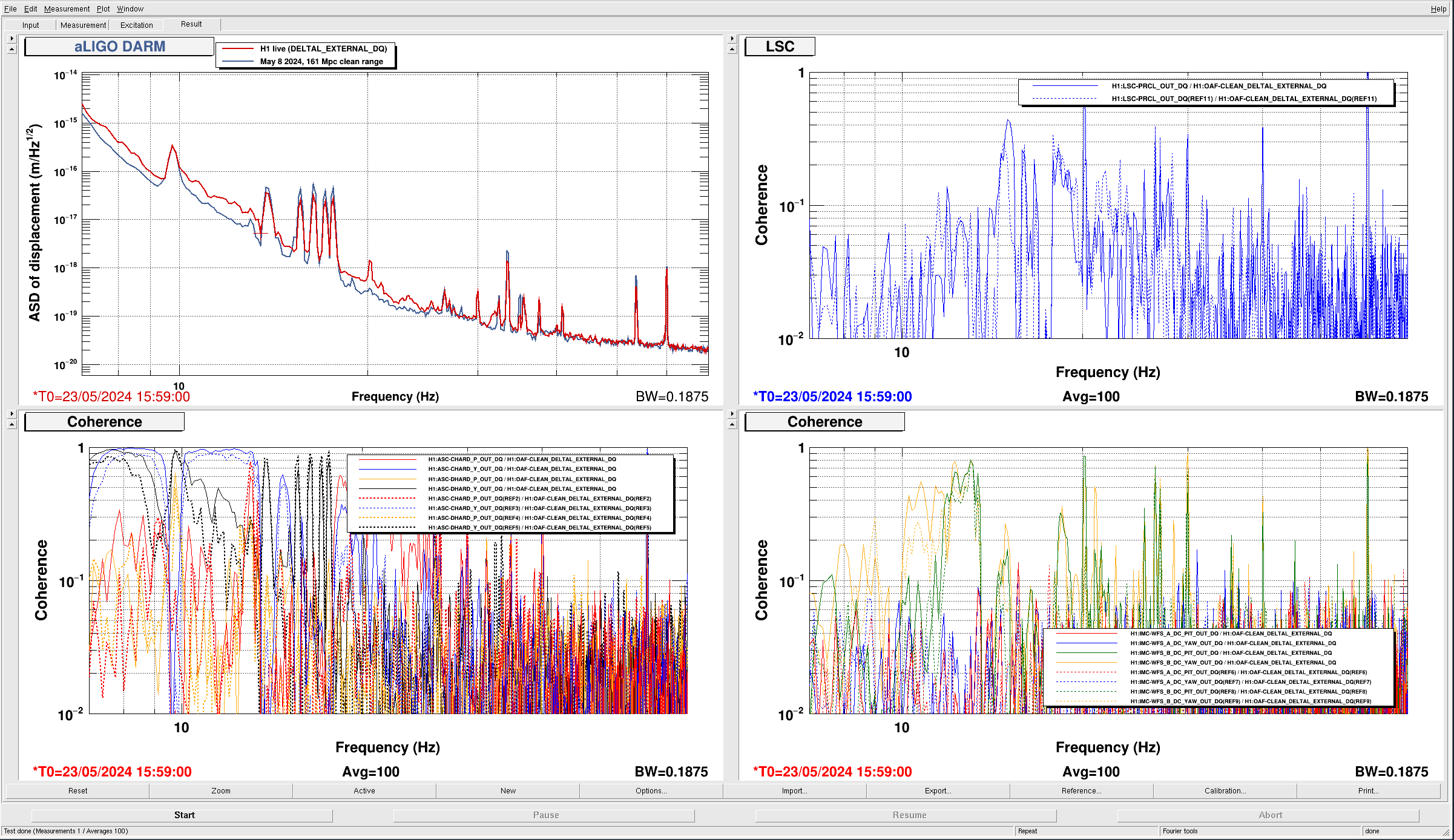
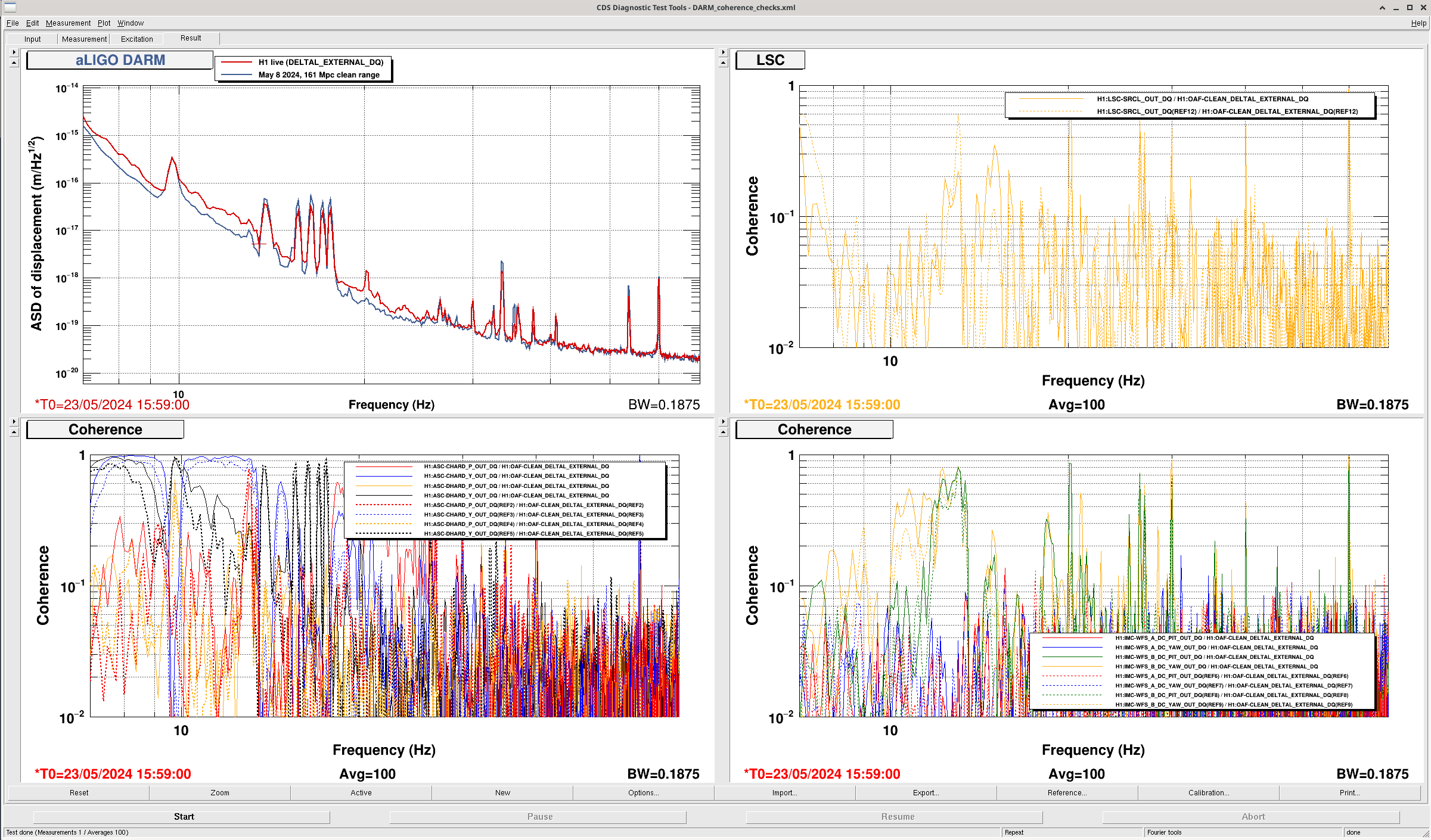
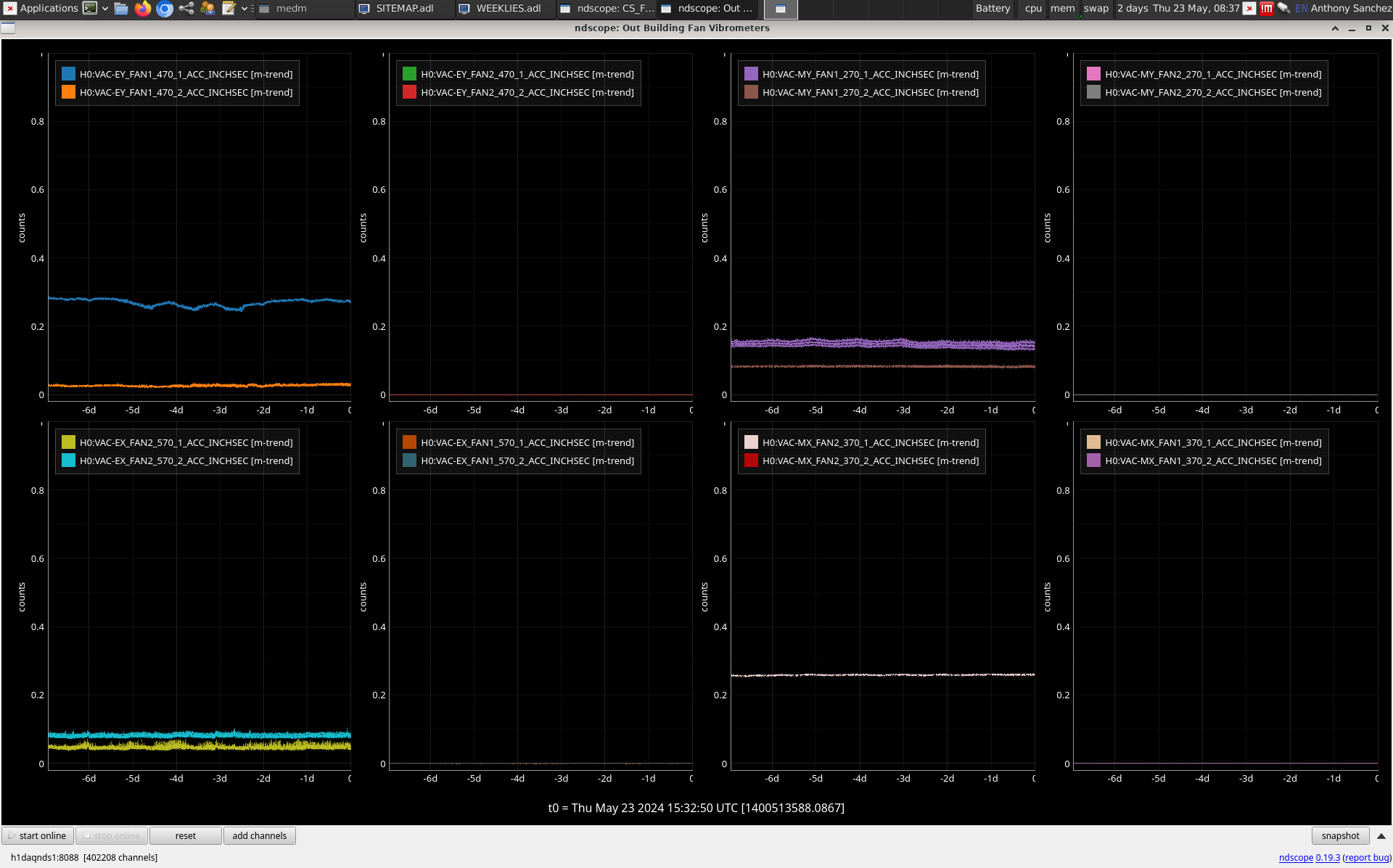
Alex has been building an improved version of the STAMP-PEM / Fscan comb comparison tool first mentioned in this alog. Essentially, this tool leverages the relatively low-resolution but much larger channel set of STAMP-PEM's coherence data to try to pick out possible new witness channels for combs identified by Fscans. Alex's results for Hanford December 30-31 2023 are attached in figure 6 (more recent STAMP-PEM data was not yet available). This reproduces prior results showing the combs in IMC WFS channels, and highlights several other channels. Following up with high-resolution Fscan spectra, I found that the PSL accelerometers which appear on the heatmap show some broad peaks in the vicinity of some comb frequencies, but are not a match to the combs at high resolution (probably unsurprisingly) so I moved on to looking at the channel mentioned above, and from there to looking at the corresponding LLO data.
I have opened a git issue here https://git.ligo.org/detchar/detchar-requests/-/issues/243 with notes on next steps & follow up; additional input welcome.