Robert and Anamaria found that there are some stray beams in HAM3 (alog 77631). As part of understanding where that could be coming from, Anamaria suggested measuring our position on PR2. TL;DR: we're the same 15mm off center in yaw that we have been, but now maybe we're starting to realize that it's too much.
Throughout O4, it looks like we've measured the beam position on PR2 three times (including today). April 2023 (alog 690225), Dec 2023 (alog 74789), and today (this alog).
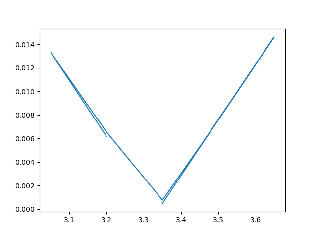
As with the previos times, changing the PR2 A2L coefficients doesn't really seem to effect the line height in DARM, but I can reduce it in PRCL_CTRL. I didn't confirm that PRCL_IN1 agrees on minimum line height with PRCL_CTRL, but I don't have reason to guess that they'd be different from one another. Today I used 29 Hz, with a line amplitude of 1 in the ADS oscillator. This made a line in DARM about 100x above the ambient for the pitch excitation (maybe a little less than that for the yaw excitation). Also, the peak in DARM seemed quite broad, with upconversion wings around it, more than I expected. I don't recall seeing such strong upconversion when doing this similar measurement recently in alog 77443.
I also measured the spot position on PRM, again with a 1 count amplitude at 29 Hz. The peak in DARM was much less broad than it was for the PR2 excitations. PRM started with no A2L gains at all.
All of my fine-tuning step sizes today were at the level of 0.03 (which is 3x smaller than my SR2/SRM steps a few weeks ago). So, indeed the PRC optics seem a little more sensitive to A2L coefficients. I left both PR2 and PRM with the coefficients I measured today.
| |
PRCL_CTRL reduction factor |
Start A2L gain |
End A2L gain |
Start inferred position [mm] |
End inferred position [mm] |
Difference in beam position [mm] |
| PR2 P2L |
10x |
-0.61 |
-0.38 |
-1.2 |
-0.8 |
+0.3 |
| PR2 Y2L |
very little |
-7.40 |
-7.45 |
-14.9 |
-15.0 |
-0.1 |
| PRM P2L |
~3.5x |
0 |
1.76 |
unmeasured |
3.5 |
N/A |
| PRM Y2L |
5x |
0 |
0.52 |
unmeasured |
1.0 |
N/A
|
Talking through numbers out loud with TJ, Corey, and Oli, and looking at D1002640 which shows the 70mm aperture size that Minhyo quotes in alog 77637, it sure seems like this is a plausible explination for the source of the light that Anamaria and Robert found. If the beam is off center on PR2 and the baffle by about 15 mm, and then 15mm away from that is the point at which, if we were clipping, we'd see a few tens of mW clipped, that clipping point total of 30 mm is starting to sound suspiciously similar to the baffle aperture radius of 35 mm.
This motivates that perhaps we really should consider trying to get closer to center on PR2. So far we haven't done so, because there are lots of alignment follow-ons that would also need to happen for the leakage beams in transmission of PR2 (eg ALS to ISCT1, POP ASC beams, POP LSC beams). But, the only one of those that we actually need in full lock is the LSC POP, so we could make some moves and as long as we're staying on LSC POP, we could see if that improves things enough to motivate making a new alignment permanent (and doing all the follow-on not-easily-reversible alignments).