Robert, Anamaria
Yesterday we opened the viewports of the oplevs for both ITMX and ITMY to find the alignment of the CP's.
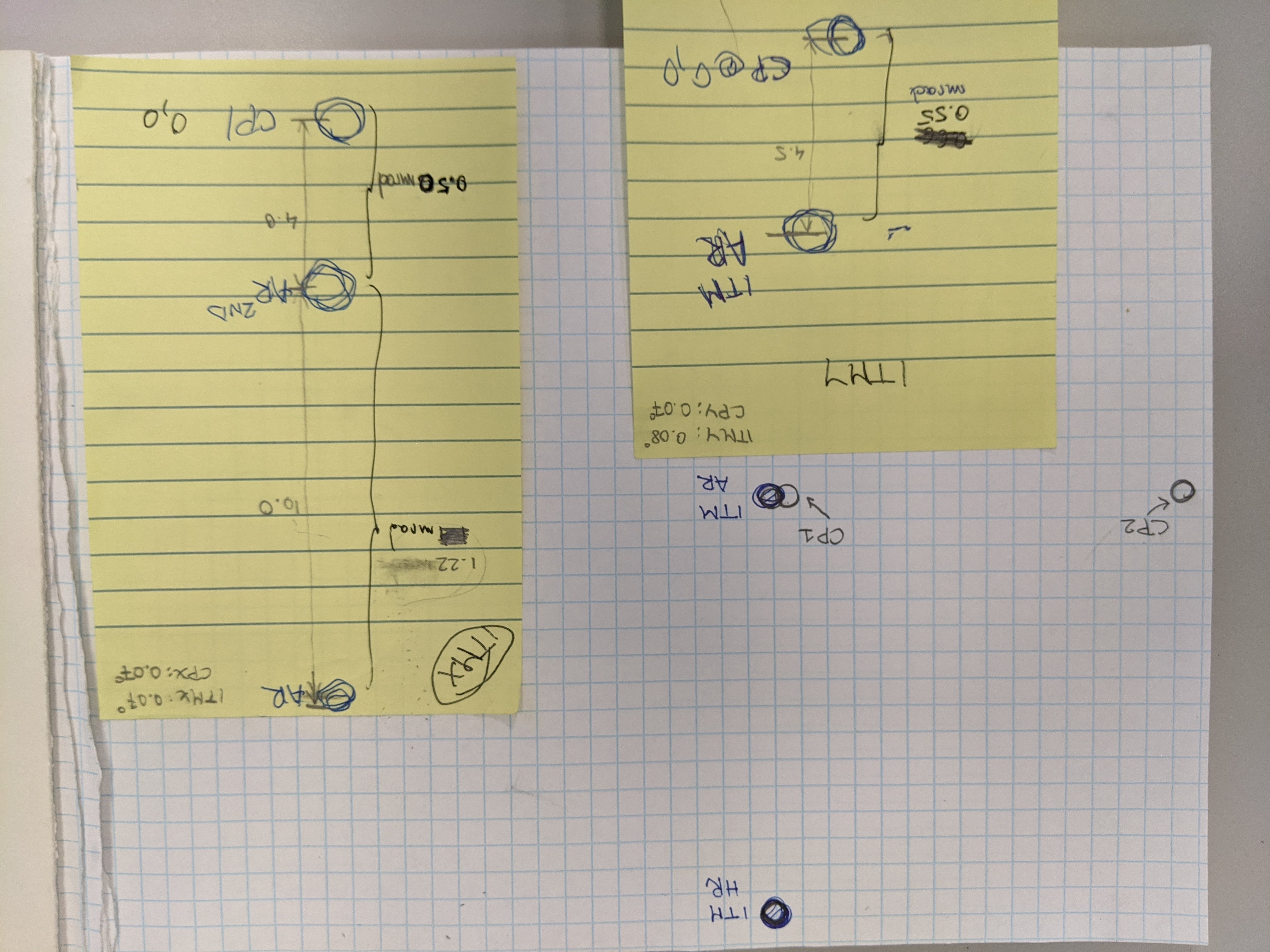
The procedure relies on the fact that the optics are not coated for red so we can see all four surfaces. The separation between the beams at this distance (~34m) is about 10cm due to the wedges (in the table below from the galaxy page). The test mass has a vertical wedge, thick down, so the AR beam will show up directly below. The CP is supposed to be perfectly parallel to the back surface so the closest surface of the CP (CP1) would land essentially right on top of the ITM AR beam. Then the CP has a similar size wedge, but horizontal, so the second CP surface would hit at the same level as CP1 and ITM AR but to the left or right, depending which ITM.
The first plot attached shows the nominal view of these beams as seen at the oplev viewport on the white page. The yellow pages were attached to the lexand covering the viewport and the beams were marked. The full view of all the beams no longer fits through the viewport due to the addition of nozzle baffles so we had to walk the oplev sender to find all the beams. For the ITMX we lucked out and the ITM AR beam was visible at the top gap of the baffle at the same time as the second AR reflection and the CP beam were visible in the aperture. As such we are able to scale the misalignments to the wedge value. We verified the CP beams by moving the CPs, and we scanned to find the second CP surface (CP2) horizontally at about the right distance from CP1.
| |
wedge ITM/CP |
misalignment |
| CP-X |
0.07/0.07 deg |
1.7 mrad down |
| CP-Y |
0.08/0.07 deg |
0.55 mrad down |
By down I mean they are further pitched down towards the arm.
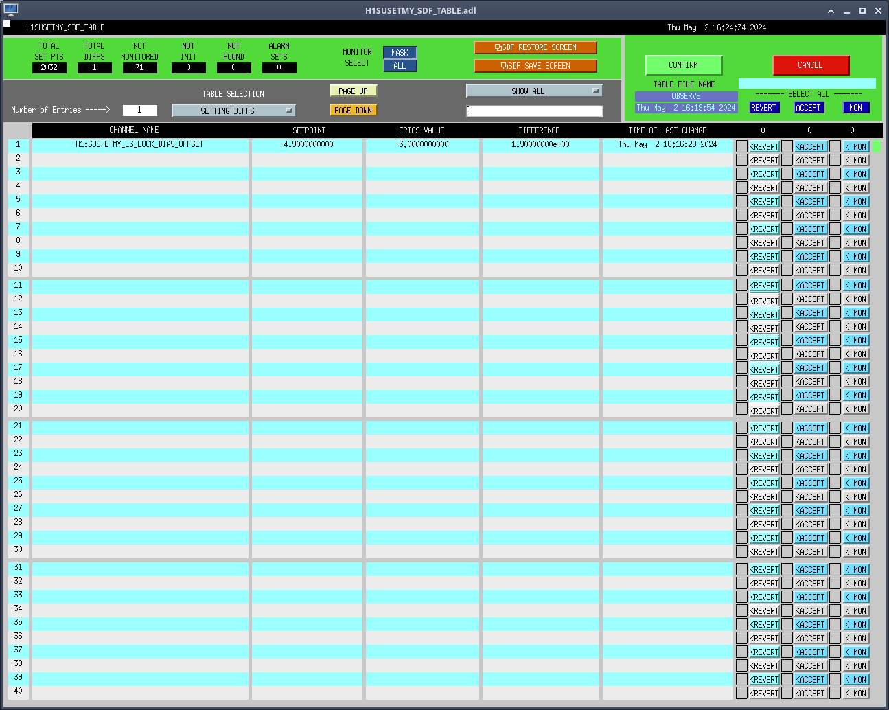
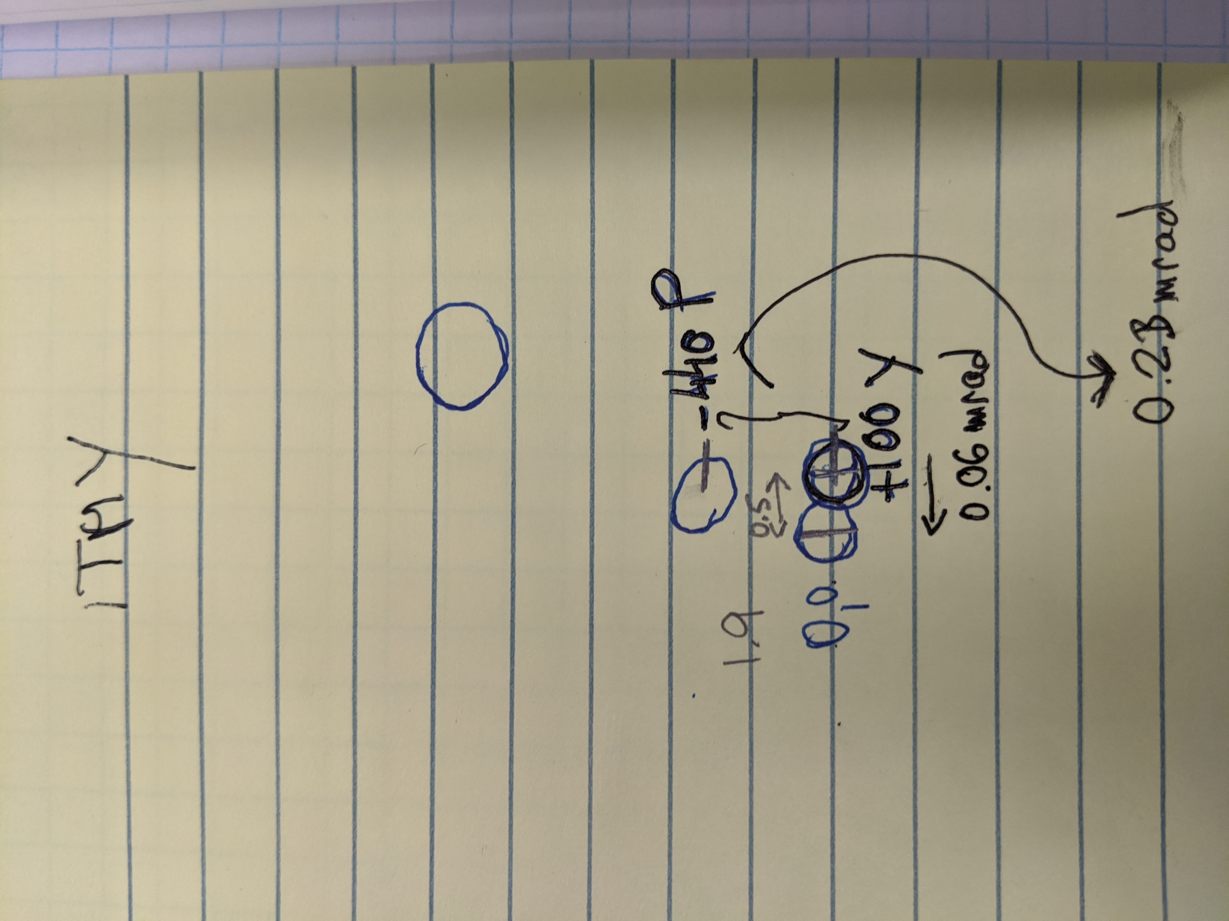
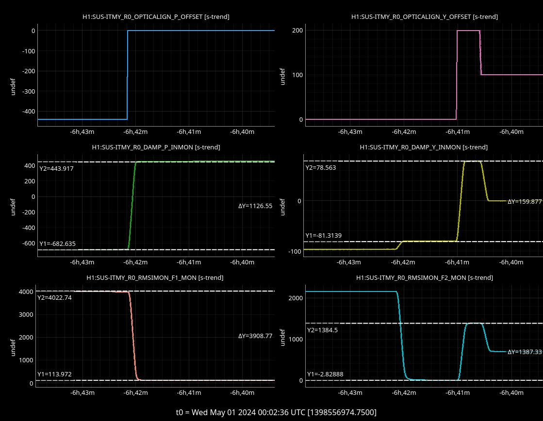
One would think that we have +/- 440 urad range in pitch on the R0, but it seems its range is much less than advertised. Even stranger, this was also found to be the case at L1, on both ITM R0. When we moved CPY, with respect to this calibration it only moves ~230 urad. So we cannot make it back to the nominal position of overlapping the ITM AR beam. For yaw we did a smaller step so more error on it, but it's about 60% of slider value. More on this later.
(CPY is the one that Robert found to modulate the noise from the MC tube baffle.) Speaking of the L1 experience, we even had to vent back in 2016 to fix one of these CP misalignments, which was too close to HR actually. The interesting thing to me, looking back, is that L1 still has a similar misalignment for CPX to the H1 CPY and we don't see as high noise coupling at the IMC tube.
CPX is very misaligned by comparison, but not linked to the MC tube scatter. Alena has agreed to help us track where these ghost beams land at P/SR3 and the scraper baffles, now that we know their exact orientation.