corey.gray@LIGO.ORG - posted 12:57, Monday 22 April 2024 (77323)
Mon DAY Ops Summary (partial)
TITLE: 04/22 Day Shift: 15:00-23:00 UTC (08:00-16:00 PST), all times posted in UTC
STATE of H1: Observing at 157Mpc
INCOMING OPERATOR: Ryan C
SHIFT SUMMARY:
- Taiwan has been rumbling with M5+ earthquakes since 2am(local) & finally ended H1's run at just under 21hrs.
- RyanS covered the afternoon part of shift.
LOG:
- 1445-1515 Optics lab cleaning (karen)
- 1515 EQ mode activated (M5.0,Taiwan)
- 1542 MY clean (karen)
- 1611-1722 PCal work (francisco)
- 1635-1935 Tony in PCal Lab
- 1726 MY ladder inspections (tyler)
- 1843 &1844 Incoming M6.1 earthquake alerts
- 1851 Lockloss due to Taiwan EQs
- 2000 Handing over to Ryan S.

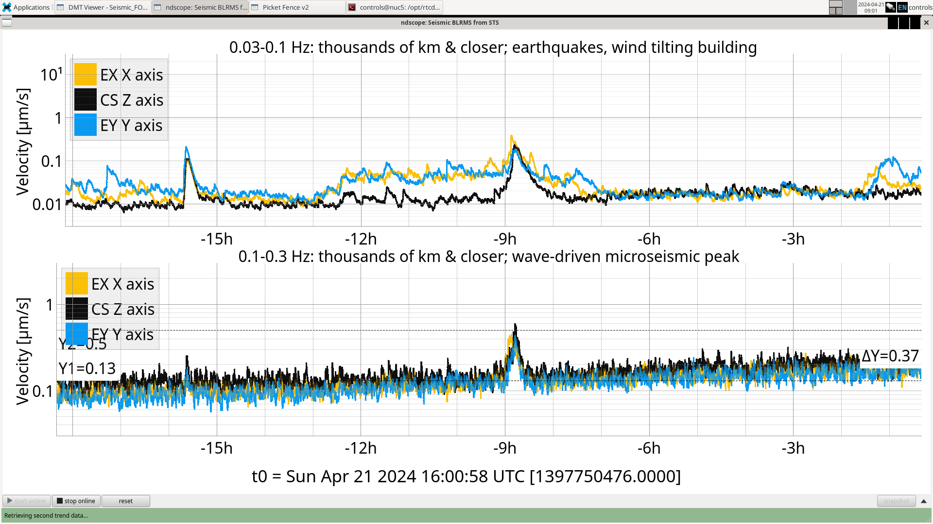
H1 back to observing at 21:18 UTC after waiting for ground motion to calm down, but more M5.5+ quakes are inbound from Taiwan.