Estimated Length Motion of the JAC
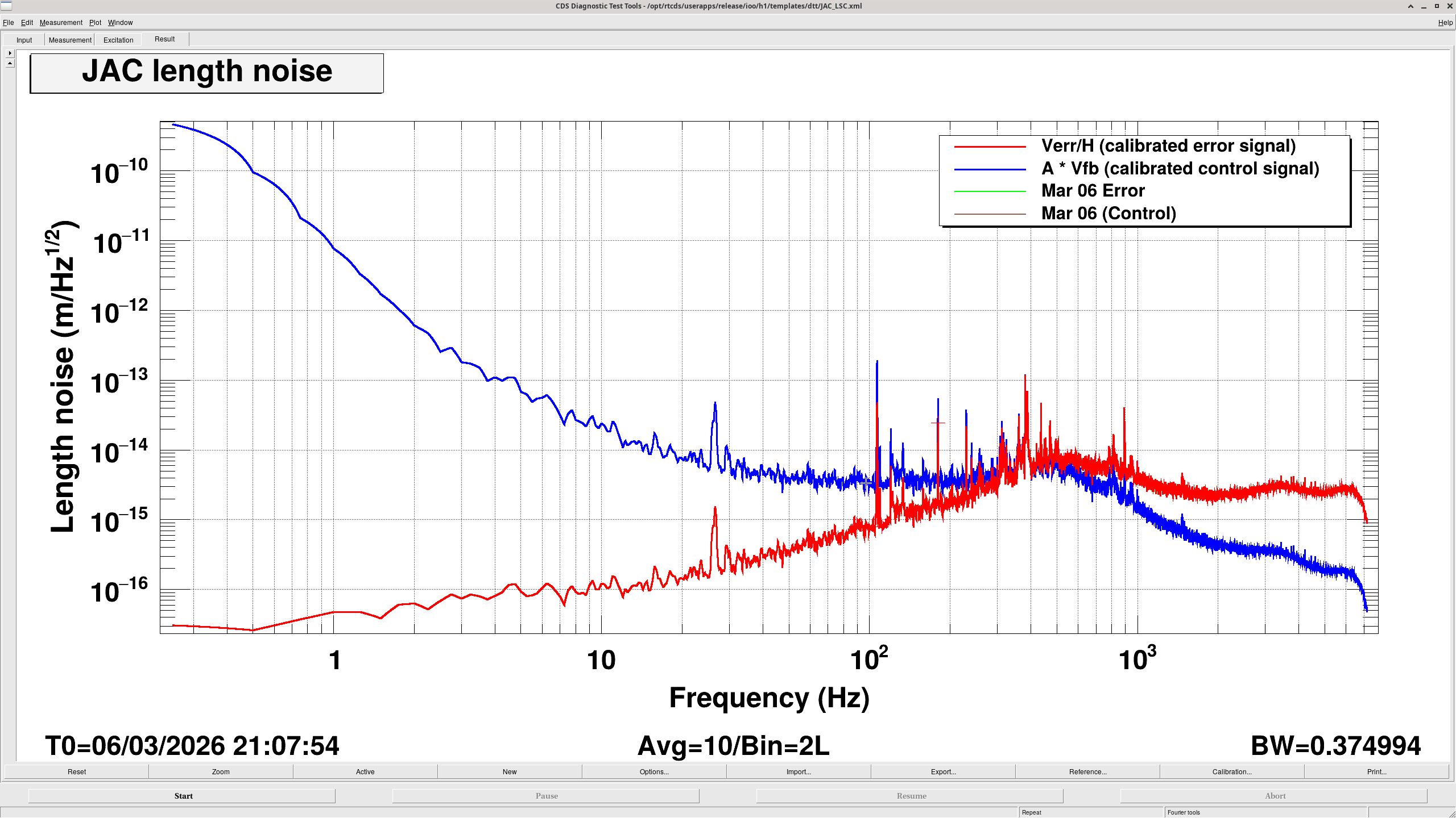
The calibrated error signal and feedback signal spectra were measured to estimate the free-running length motion of the JAC. Below the unity gain frequency (UGF = 400 Hz), the feedback signal represents the cavity length motion, while above the UGF the error signal represents the motion. The estimated length noise is well below the design assumption and does not appear to limit the JAC performance.
Method
The spectra of the calibrated error signal and feedback signal were measured to estimate the free-running length motion of the JAC.
- Below the UGF (400 Hz), the feedback signal represents the cavity length motion.
- Above the UGF, the error signal represents the cavity length motion.
Around 400 Hz, the spectrum appears slightly inflated because of the phase bubble, but the actual noise level is expected to be approximately flat in that region.
Observed Features in the Spectrum
- Above 30 Hz
Above 30 Hz, the spectrum becomes flat. This is likely not real cavity motion, but instead electronics noise from the readout chain. A more careful calculation is needed to identify the exact source, but it is most likely the photodiode or the ADC.
Since the incident power is currently 1 W, this noise floor is expected to decrease if the input power is increased.
- Below 10 Hz
Toward DC, the spectrum rises approximately with an f-3 slope. This is interpreted as drift in the PZT control signal caused by temperature drift.
Therefore, the actual cavity length variation at low frequencies is expected to be smaller than what appears directly in the measured spectrum.
- Estimated Length Noise
Looking at the spectrum around 10 Hz, where the above effects are not expected to dominate, the cavity length noise is estimated to be approximately 2 × 10-14 m/rtHz.
In the design, the cavity length motion was conservatively assumed to be 1 × 10-12 m/rtHz at 10 Hz.
Therefore, the measured result is well below the design assumption, indicating that the loop design and the JAC do not introduce problematic intensity noise or phase noise.
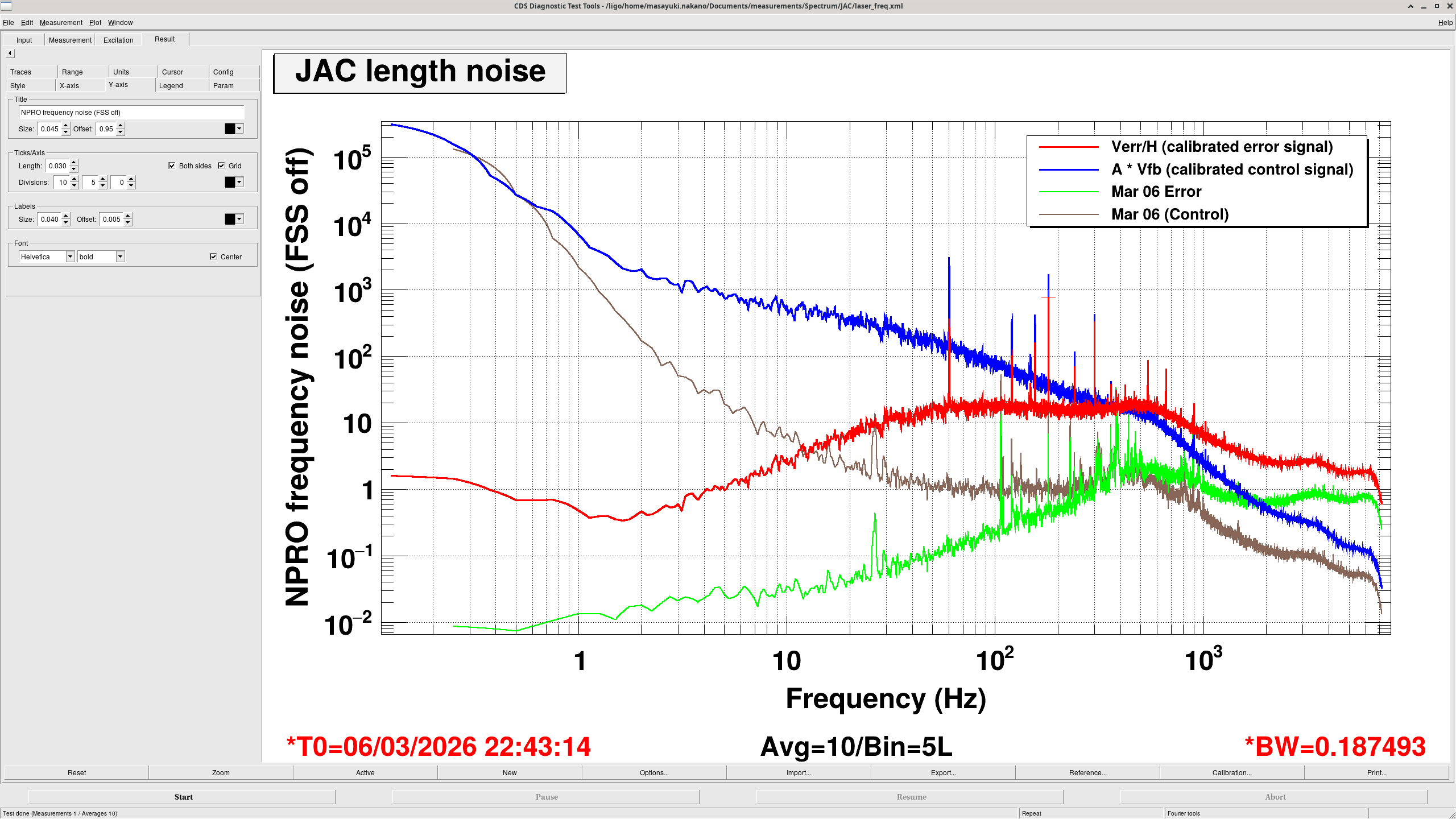
Sanity Check with the FSS Unlocked
As a sanity check, the same measurement was repeated with the FSS unlocked. In this measurement, the vertical axis was converted into laser frequency noise by multiplying the calibrated length signal by
FSR / (lambda / 2)
where the free spectral range is given by
FSR = c / L
with c the speed of light and L the cavity round-trip length. For the JAC, L = 2.02 m.
The resulting spectrum, shown in the second plot, is approximately 100 Hz/rtHz at 100 Hz. This is consistent with the typical frequency noise of the NPRO laser.
This also confirms that the JAC is sufficiently quiet compared with the NPRO noise level.