I have been testing a high voltage version of the cps in the staging building for several months now. These new sensors are supposed to have something like 4x lower noise than the cps we currently use, cps noise limits table motion between about .5-10 hz. This morning I tried to test them on the HAM7 ISI this morning. The test just required disconnecting the existing satellite chassis at the chamber and connecting a new set of in air electronics outside the chamber.
I did a couple quick transfer functions to check the sensor responses made sense, then turned on the isolation loops. Loops were stable, no problems there, but I didn't get good performance data. There were a number of people working near the chamber, so it wasn't very quiet. It also didn't seem like the HV cps noise floors were as low as I've been able to get on my test stand in the staging building.
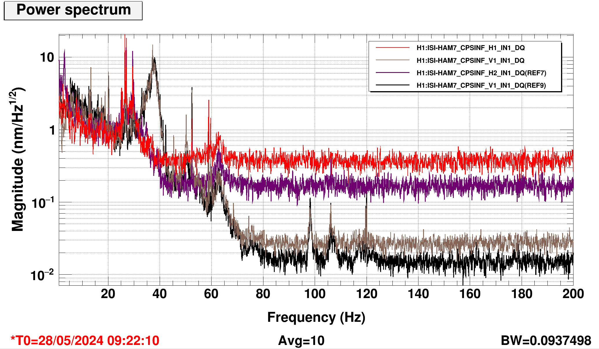
Attached plot compares individual some cps noise floors, red and green are regular sensors from some time in the middle of the night, purple and black are the lowest noise high voltage sensors from my test this morning. Unfortunately, the other 4 HV cps were the same noise or higher than the regular sensors. I didn't have a lot of time to try to poke at the new sensors. I'll try again next week, it would help if I can have it quiet around the chamber it would help, but that doesn't affect the 100hz noise.
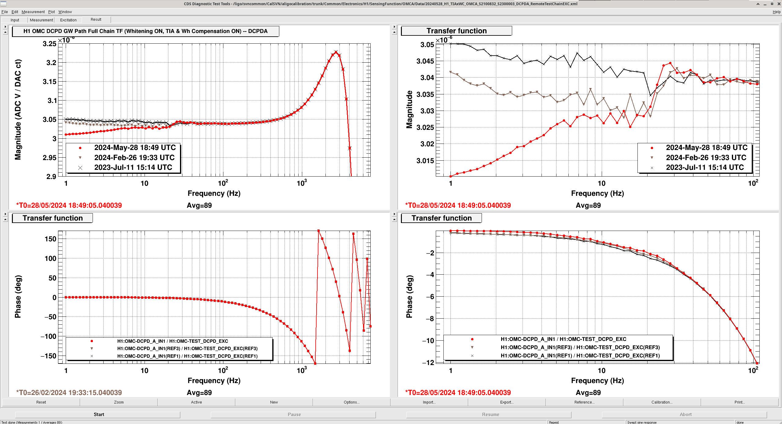
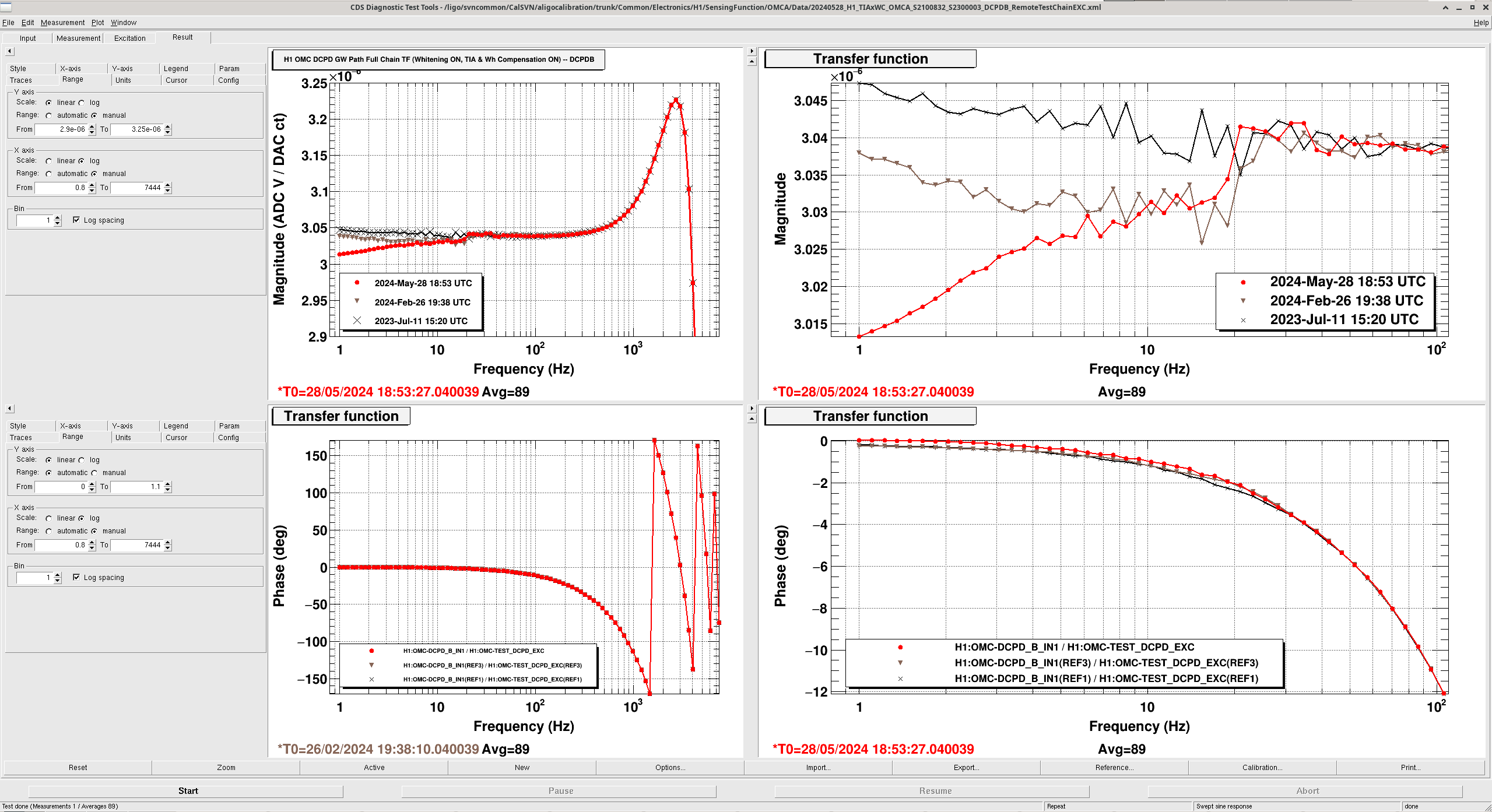
J. Kissel EDIT :: False Alarm -- see comment below! Since I'm at the "what does it all mean?" stage of madness with the OMC DCPD Transimpedance Amplifier (TIA), I decided to make it worse -- I remeasured the original transfer function that triggered me worrying about the TIA response in after the OMC swap (see LHO:75986). I did this to try to corroborate whether there is a change in the DCPDA response above 1 kHz as mentioned in LHO:78090. This transfer function is the remote, DAC-driven measurement of the whole DCPD sensing chain -- the transimpedance amplifier, the whitening chassis, and the front-end compensation for the frequency response of those -- this has been described most recently in LHO:71225. I *don't* see a difference above 1 kHz, but I *do* see more difference in response below 25 Hz than I had in 2024-Feb-26. See the attached transfer functions of the DCPDA chain and the DCPDB chain. Black is pre-OMC swap, 2023-Jul-11. Brown is post-OMC swap, 2024-Feb-26. Red is today, also-post OMC swap, 2024-May-28. All measurements use the S2300003 whitening chassis, and the compensation from the 2023-Mar era compensation we've been using throughout O4. The only "oh, well it could just be" that I can think of immediately is that the DCPDs had been powered down from 10:10a to 11:30a PDT today to characterize the measurement setup in analog (see LHO:78090), and these were measured "only" 20 minutes after being powered back on at 11:50a. So -- we'll have to take the measurement again at the next opportunity -- such that the TIA electronics have what we think it the appropriate amount of time to thermalize -- a few hours. Just maddening. Data lives in /ligo/svncommon/CalSVN/aligocalibration/trunk/Common/Electronics/H1/SensingFunction/OMCA/Data/ 20240528_H1_TIAxWC_OMCA_S2100832_S2300003_DCPDA_RemoteTestChainEXC.xml 20240528_H1_TIAxWC_OMCA_S2100832_S2300003_DCPDB_RemoteTestChainEXC.xml
False alarm! It appears indeed that I had inadvertently captured a thermal transient of the transimpedance amplifiers -- since it had only been 20 minutes since I'd turned on the power to the preamps. See LHO:78112, where I took this same measurement again, and the response restored to the same post-2024-OMC-swap-vent response.
J. Oberling, R. Short
Our PMC Refl signal has been slowly increasing over the last several months; by extension this means that PMC Trans and the amount of power available to the IFO has been decreasing. Ryan and I went into the PSL enclosure to take a look at things.
We began by using an IR viewer to look at the PSL optics. All looked as expected except for M11, which was a bit brighter than we both recall; this is the 1st of the two turning mirrors that steer the beam into the PMC. We noted to take a close look at this optic once we had things turned off. We next took several power measurements around the PMC, all done with the ISS OFF; with the ISS OFF the power moves around a little bit more, so I've included the min and the max readings at each location:
Things here match our PD calibrations OK. One thing we noticed, the amount of ISS diffracted power was a little low for the amount of variation we were seeing in the output of Amp2; we therefore adjusted the ISS offset a little to bring that bank back up a bit, to ensure we have enough power available to counter the swings in Amp2 output. We finished here with an offset of 4.7, and 4.2W in the ISS diffracted beam (again, this was with the ISS OFF). The ISS now defaults to ~3.0% diffracted power when it is OFF (this change was accepted in both SAFE and Observe SDF).
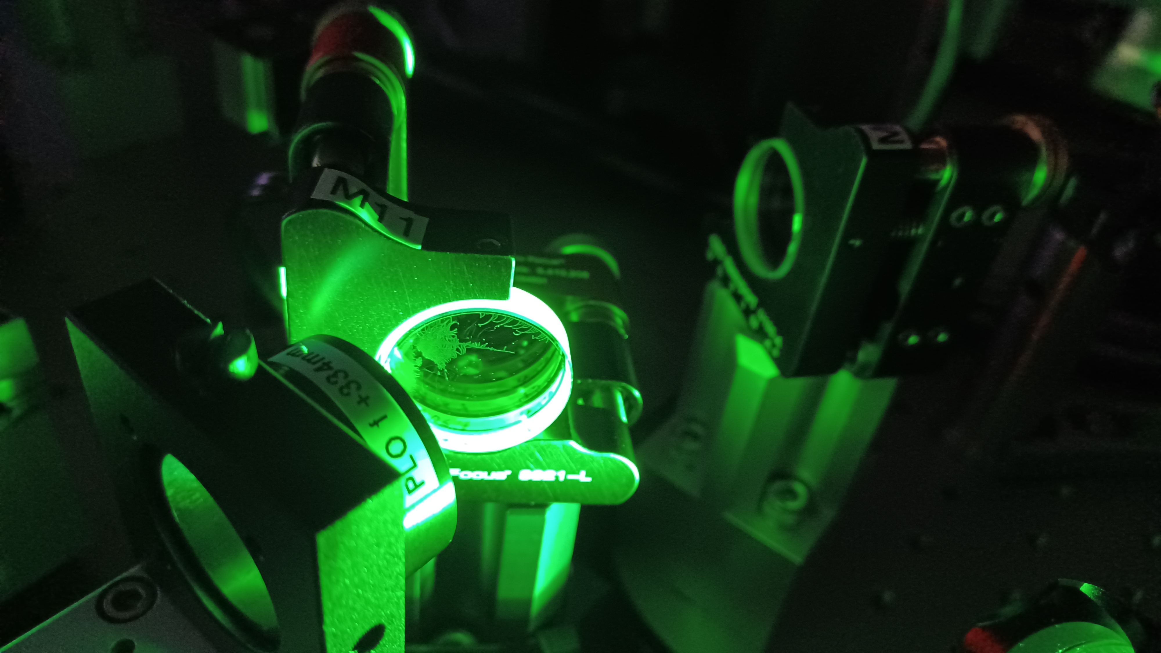
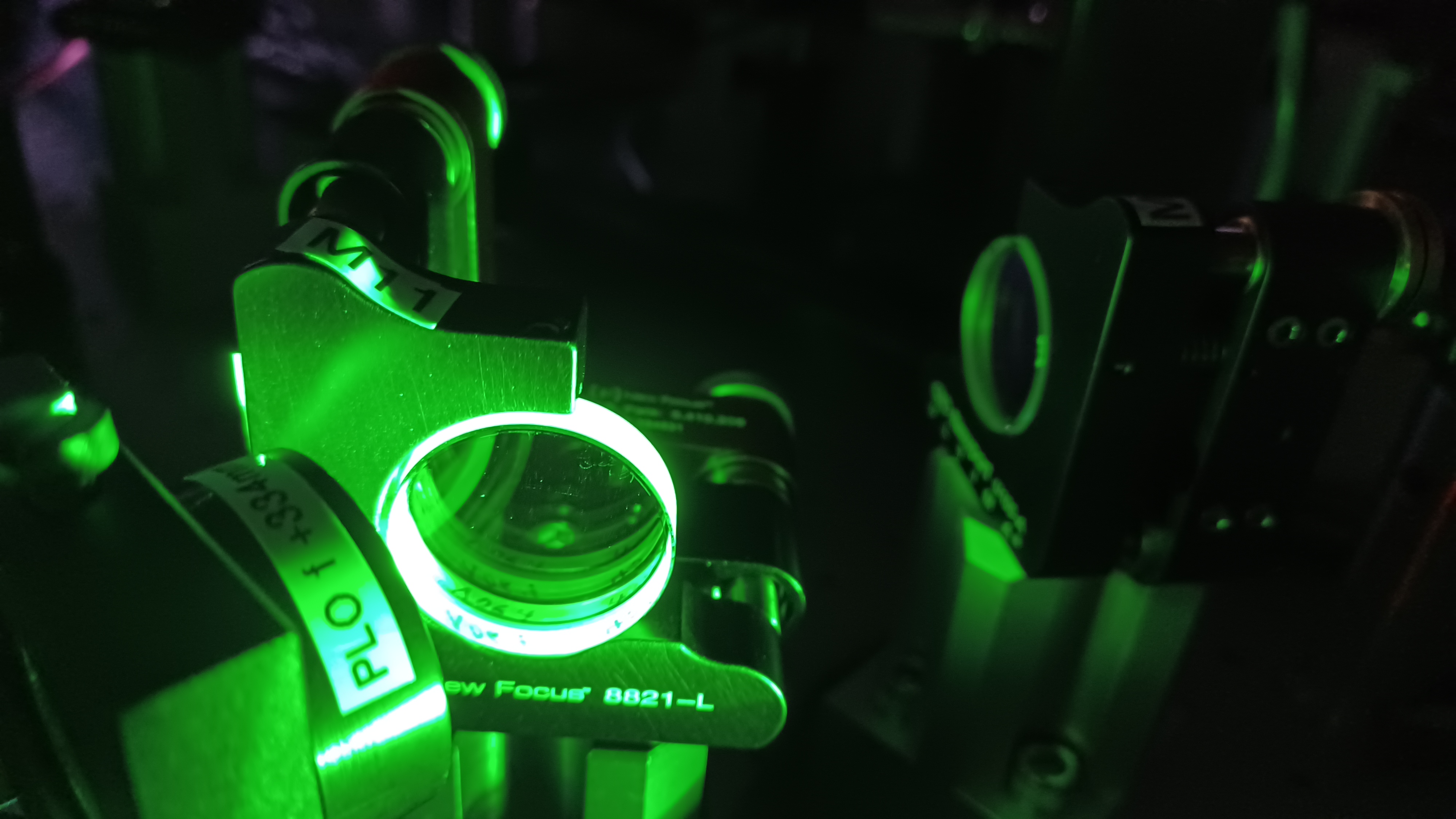
This done we moved on to inspecting optics with our green flashlight. With the PMC unlocked and the PSL external shutter closed, we looked at all of the optics between the external shutter and the PMC. Sure enough, all optics looked good except for M11 (see first picture). 8 in situ, very careful drag wipes later the optic looked much better, and better yet no signs of damage (see 2nd picture). Still some small dots on it that I couldn't remove, my guess is these are small coating defects that the green flashlight is really highlighting. We then opened the shutter and viewed the mirror through the IR viewer, and while it was still a little bright it did look much better. The PMC relocked without issue, but PMC Refl was higher than when we started (likely due to the PSL environmental controls being on and slight alignment shift during drag wiping M11).
Last, we checked centering on the PMC locking PD and the PD that reads PMC Refl. These PDs were well centered, with no improvement made when we tried to adjust the alignment onto the PD. This tells me that we have not seen an alignment shift between Amp2 and the PMC, which tracks with the fact we have acheived almost zero improvement to PMC Trans/Refl by tweaking beam alignment. Since we already had a mutlimeter set up, we took a visibility measurement for the PMC:
The visibility measurement looks good, really good, and does not match what we see with PMC throughput. Using our power measurements from earlier, we're only transmitting ~83.7% of the incident light through the PMC, nowhere close to what our visibility measurement suggests. This reminds me of the old loss issues that plagued the original glued aLIGO PMCs at LLO, and spurred the development of the all-bolted PMCs we're using now at both sites. Could our issue be loss build-up in the PMC? This suggests that is a likely possibility.
At this point we left the enclosure to consider next steps. We do have a spare all-bolted PMC that we could swap in and see how it performs. This is, theoretically, a quick process, as the all-bolted PMCs have magnetic ball mounts that help preserve PMC alignment upon removal (we tested this a little when we installed this PMC in April 2018, and it seemed to work well). For now, the PMC Refl signal is still higher than when we went into the enclosure, by almost 3W. This isn't entirely surprising, as I did clean mirror M11 and the PSL environmental controls were on for a couple hours. We're watching things for time being, hoping that PMC Refl comes back to "normal" once the enclosure thermalizes; if it doesn't then either Ryan S. or myself will do a quick alignment tweak at an available opportunity (or next Tuesday if no opportunistic time pops up between now and then). Probably more to come here.
This closes LHO WP 11881.
J. Kissel, [emotional support from L. Dartez remotely] Executive Summary Contrary to the grand plan, I instead unplugged and re-plugged in some cables, and lost 4 hours of my life. The OMC DCPD electronics chain remains as it did before today. I'm confused yet again. Full Summary After we last left the saga of "the in-vacuum OMC DCPD Transimpedance Amplifier (TIA) frequency response has changed a little since the OMC Swap; let's re-measure it in analog" (LHO:77735), the 2024-May-13 plan was to swap the apparently broken S2300003, D2200215-style OMC DCPD Whitening Chassis, for a spare (I chose S2300002), in hopes that we'd be able to make a new analog measurement of the TIA without the non-linearity in the whitening chassis' measurement setup. Today, the installed-in-the-racks measurement setup using S2300002 got even more weird :: very different from the exact same setup of the same chassis in the EE shop. "Weird" is :: 2 [V/V] rather than 1 [V/V], and :: a very obvious, 10 [%] / 3 [deg] wiggle, frequency response above 1 kHz, rather than "subtle, slightly different nonlinear roll off." Indeed, to confirm my insanity, I quickly switched over to CH B of S2300003 while there with everything else the same, and it's similarly weird -- and different from the previous in-rack measurements taken only a few weeks ago where I'd probed its subtle non-linearity around 1 [V/V]. Just maddening. That being said, after dividing the maddening response of the measurement setup out of the data we really want -- the analog measurement of the in-vacuum TIA -- we see a good clean measurement, with finally with the same DC gain as the good old 2023-03-10 measurements. BUT -- DCPD A's response shows change from the best 2023-03-10 measurement data set -- but at *high* frequency rather than "below 25 Hz." I don't think this is real. More on this in a follow-up aLOG. In the end, after four hours in front of the SR785, Louis and I decided to revert the signal chain back to using S2300003 as had and has been the case for all of O4. I'll hang my head, eat my hat, put foot in mouth, and head back to the EE shop. Attached is a collection of plots the shows today's results. :: Pages 1 & 2, for DCPDA and DCPDB, respectively, the TIA response, with the maddening measurement setup divided out. One can see that the for DCPDB (page 2) that today's 2024-05-28 measurement divided by the currently installed compensation (from 2023-03-10) agrees very well with the 2023-03-10 measurement over compensation. However, for DCPDA (page 1), we see a diverence from the model and old measurement above 1 kHz. :: Pages 3 & 4, for DCPDA and DCPDB, again show the obscene difference between today's measurement setup's response -- the 2 [V/V], with 10 % / 3 deg wiggle above 1 kHz -- and the previous "bad" result from 2024-04-23, and the originally "I'm happy with that" 2023-03-10 result, both of which are 1 [V/V] with "a little bit of phase loss, but that's it." :: Page 5 shows the ratio of all of today's measurement setup responses, showing that even from channel to channel and chassis to chassis, I get this exact same response. I even swapped out the SR785 accessory box for another to see if this was the issue, and I got the same response. The only piece of electronics left as suspect is the SR785. But -- (1) Out of the utmost caution, I run a factory reset on any SR785 I touch before I begin configuring it for measurement, and (2) This is a *differential* transfer function measurement with the SR785. That means the ratio CH2 (A-B) / CH1 (A-B) is changing. I find it quite hard to believe that this could be happening. And in case you're suspicious that "Oh, you must have blown the input electronics by driving too hard into it," We're careful to keep the input voltage for each A and B spigot of CH1 and CH2 below the specified 5 [V_pk], and we're watching for its ADC saturations at all times. So, ya, maddening. More details in the comments for posterity.
First attachment: pictures of the momentary installation of S2300002 into ISC-R5, both where I landed it in U26, and then followed up with pictures of the measurement while measuring it. Second attachment: A copy forward of the diagrams of the measurement setup that I followed during the above measurements. (The pictures from above show it while I was measuring the TIA; I did not take pictures of the measurement setup, but I *promise* you it matches the diagram. I checked 15 times once things started to go pear-shaped with the frequency-dependent, 2 [V/V], business.) Third attachment: A post-mortem collection of photos proving that the system has been completely reverted, leaving only S2300003 in U24, with all cables reconnected.
The data and script to quickly plot it from today's work lives in
/ligo/svncommon/CalSVN/aligocalibration/trunk/
Common/Electronics/H1/DCPDTransimpedanceAmp/OMCA/S2100832_SN02/20240528/Data/
I attach the measurement notes.
It was the SR785 that has been slowly failing in a subtle way. That's why the "measurement setup" measurements have been continually changing, and in this aLOG look totally bonkers with the 2 [V/V] and a frequency-dependent wiggle above 1 kHz. See LHO:78165.
Andrei, Sheila
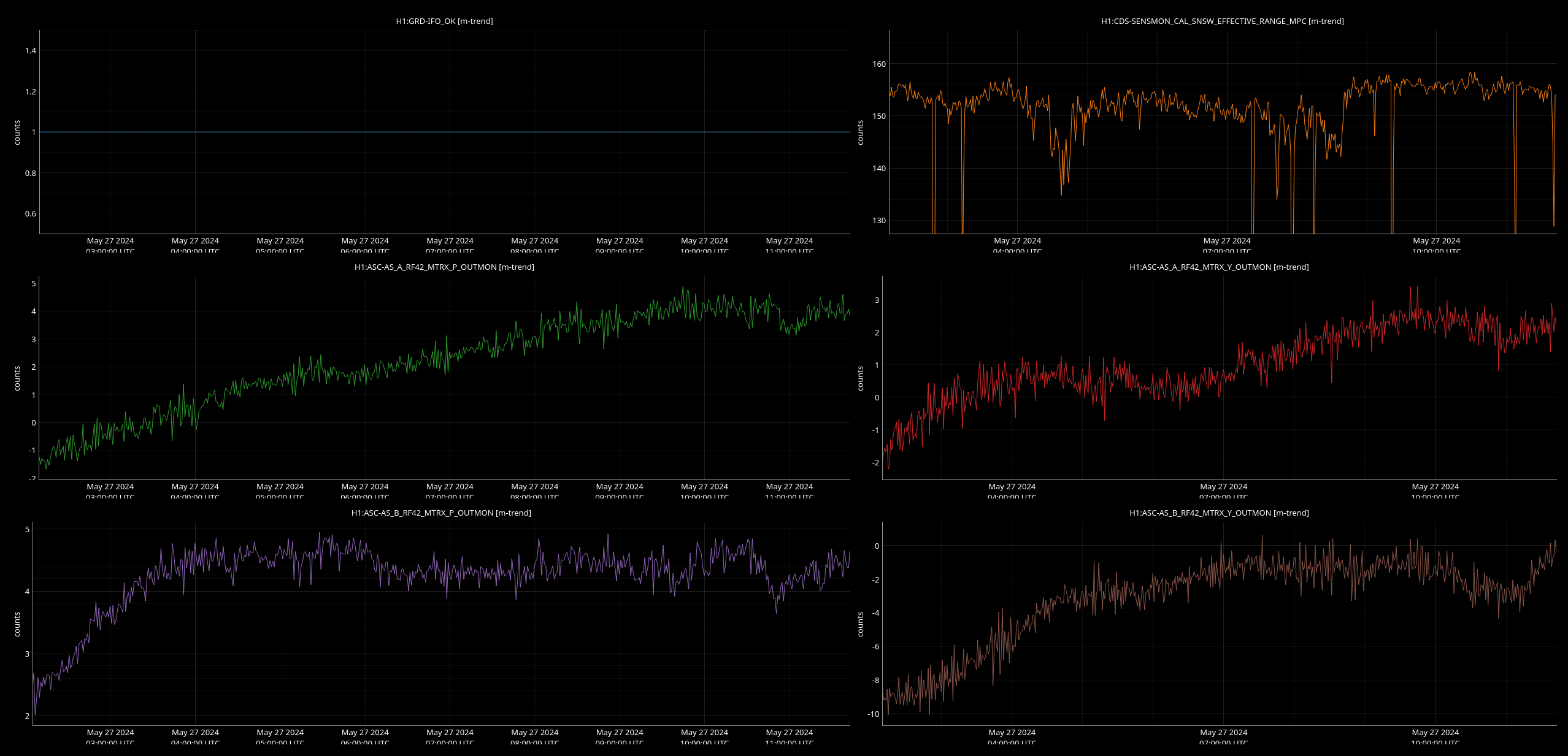
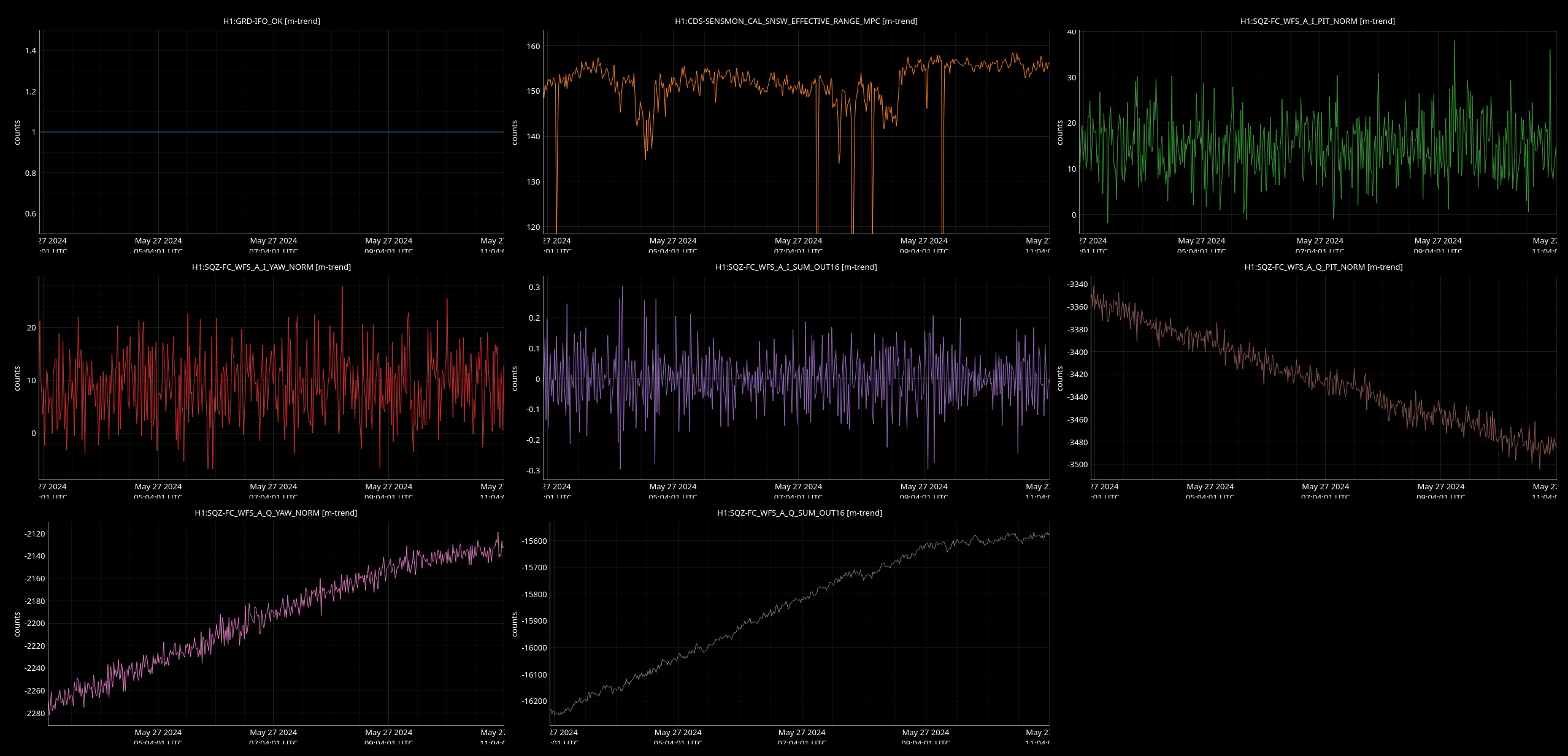
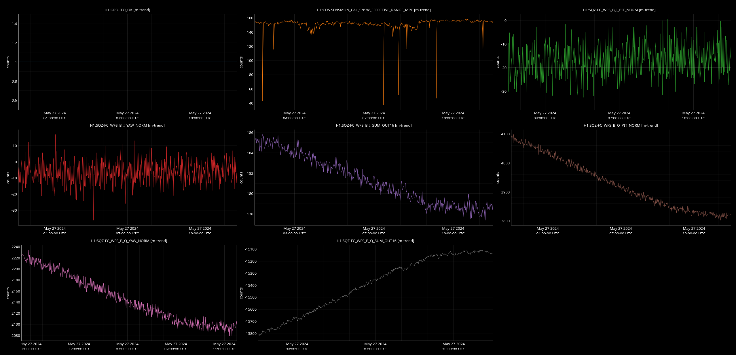
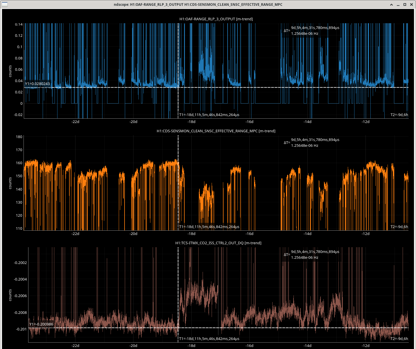
We've analyzed the time-traces of the effective range (H1:CDS-SENSMON_CAL_SNSW_EFFECTIVE_RANGE_MPC) along with the alignment channels FC_WFC_A(B) and AS_A(B)_RF42 (see attached figures). We found no observable dependance between those.
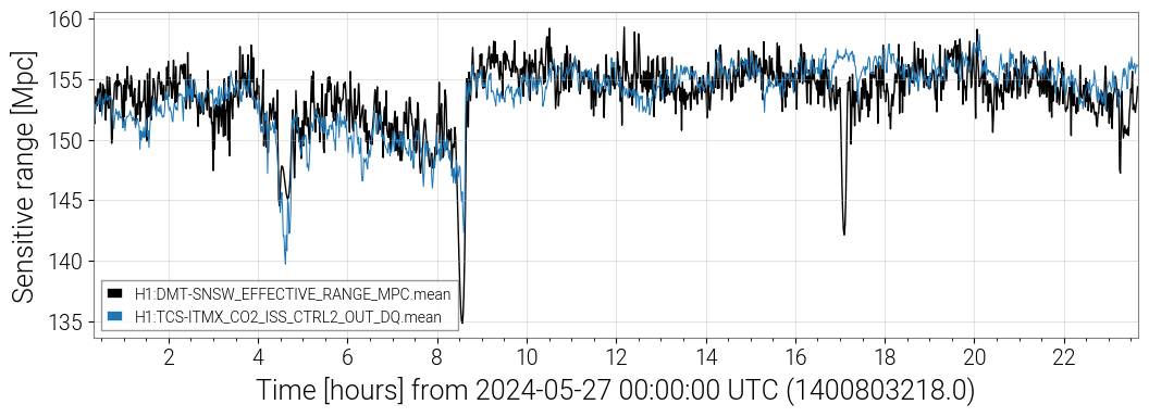
During the time period being investigated in this alog on May 27, LASSO flags H1:TCS-ITMX_CO2_ISS_CTRL2_OUT_DQ as strongly correlated with the range. This channel and other related channels have been flagged as highly correlated to the range in recent days, but this time period shows the strongest correlation.
Jumps in this TCS channel correlate with range jumps, as shown in the attached comparison of the TCS and range trends on May 27.
Tagging TCS
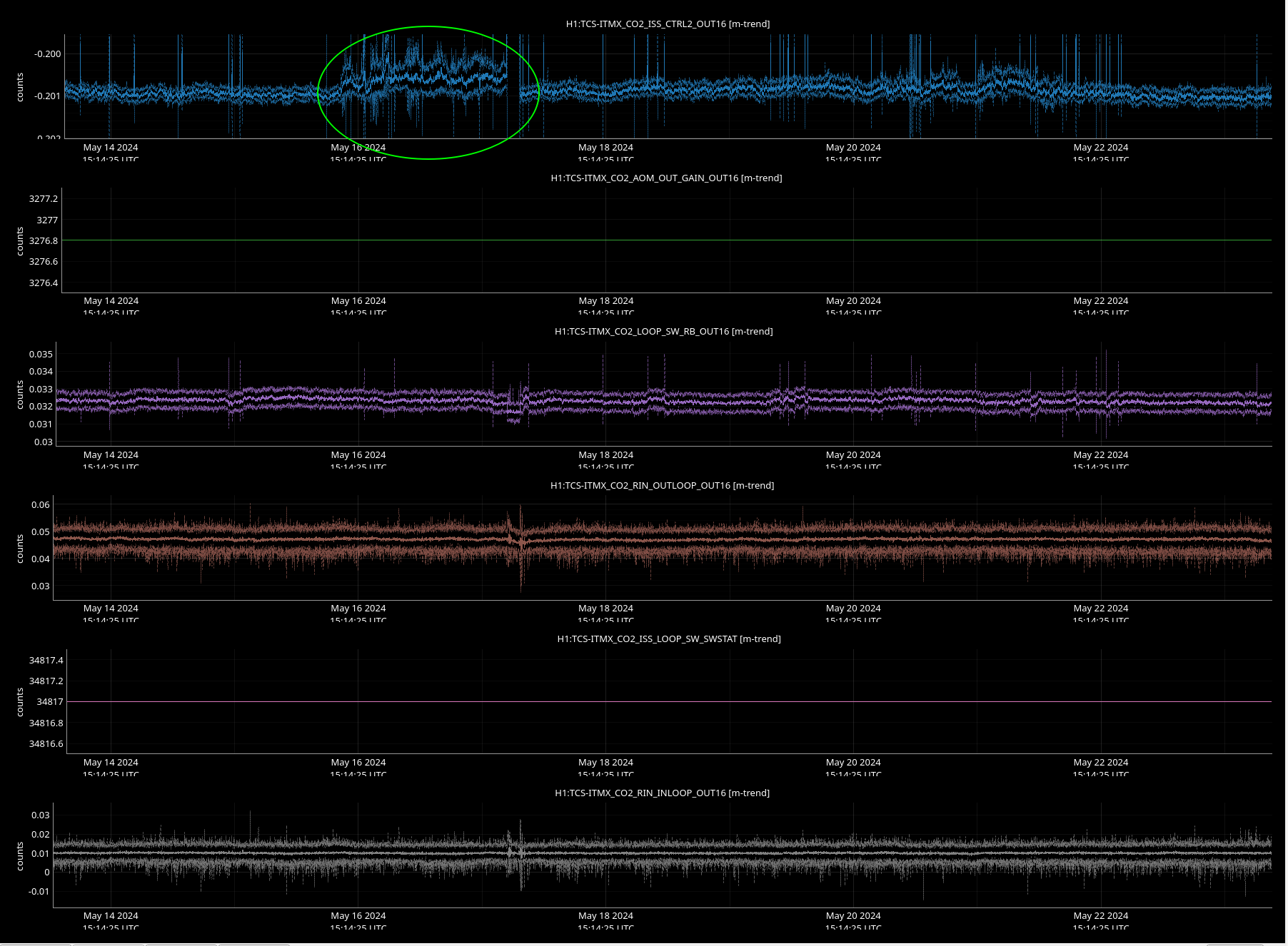
This TCSX ISS correlation is a bit odd since we aren't using the ISS and the AOM, I believe, is completely unplugged. That said, I looked at some of the channels in that system and there is some extra noise seen around the times Derek posted (see May 16th example). I wonder if this points to a larger grounding issue or some other electrical problem that is seen more broadly.
These range fluctuations that we think are related to the squeezer started (I think) on May 16th: 77869
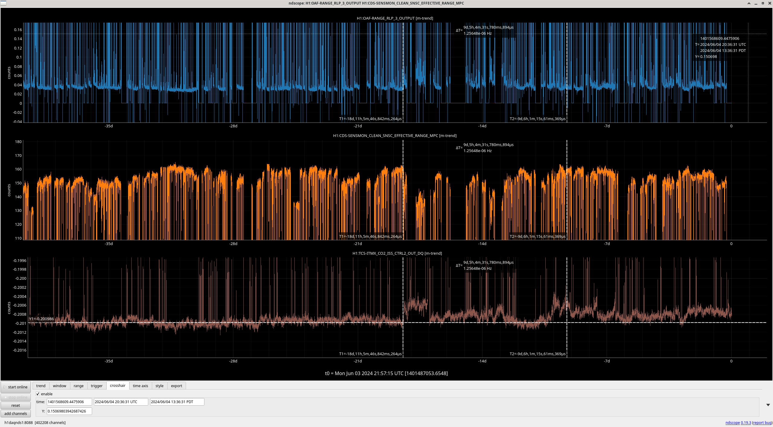
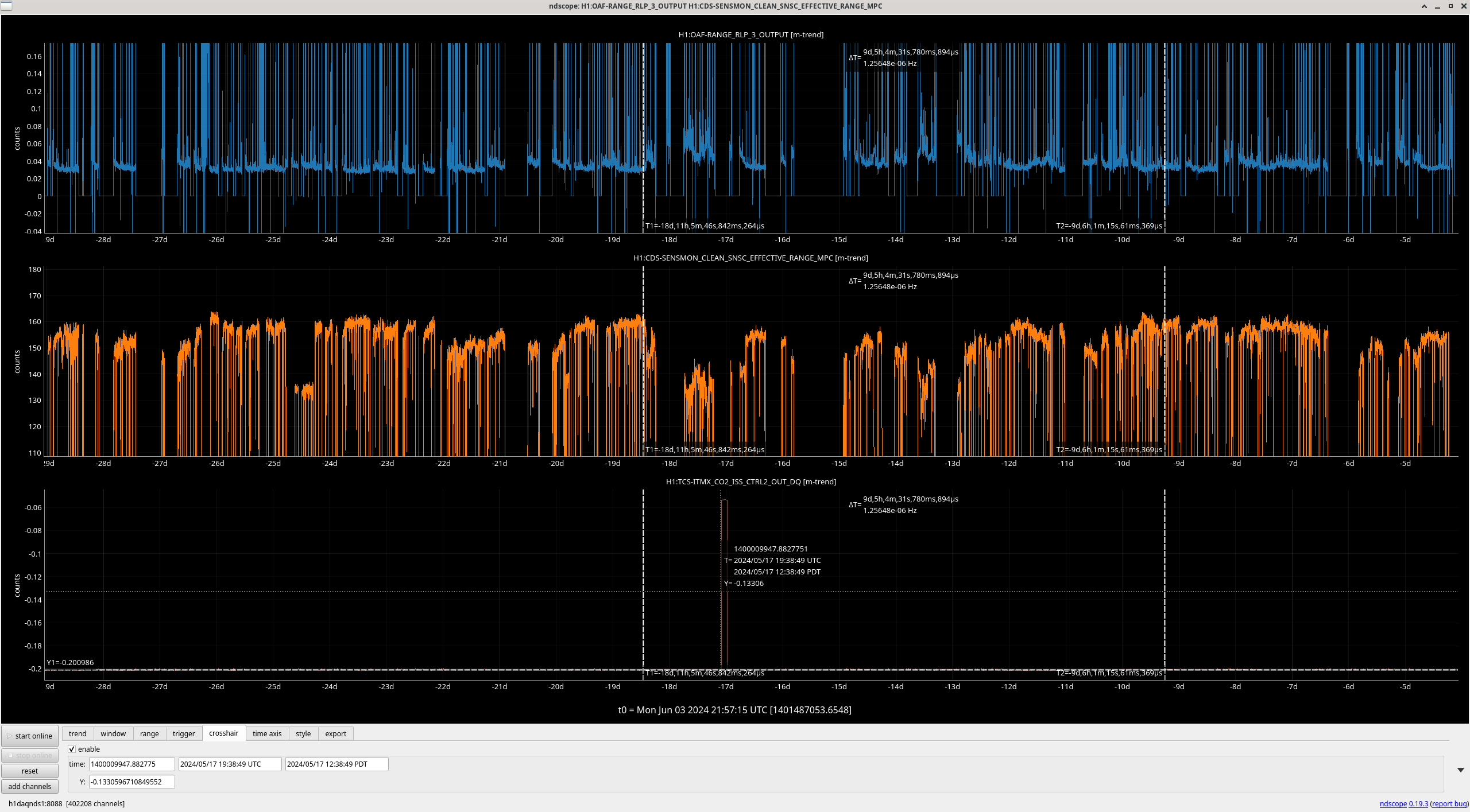
The first time cursor in the attached screeshot shows that range drip which I thought was traffic related at the time. Looking at the long term trend of this CO2 ISS control signal, there is a chance in charachter at this time, with more drifts in the signal level since. The second screenshot shows that this channel had a large jump on May 17th around 20:04-22:33 UTC.
There is a DARM BLRMS that may be more useful for tracking this noise than just looking at range, H1:OAF-RANGE_RLP_3_OUTPUT. (third screenshot shows this also had a change point and drifts more since May 16th.)
The LVEA has been swept, the FARO is being left plugged in as usual, there were some ladders left out along the yarm.
TITLE: 05/28 Day Shift: 1430-2330 UTC (0730-1630 PST), all times posted in UTC
STATE of H1: Preventive Maintenance
OUTGOING OPERATOR: Ryan S
CURRENT ENVIRONMENT:
SEI_ENV state: MAINTENANCE
Wind: 6mph Gusts, 4mph 5min avg
Primary useism: 0.02 μm/s
Secondary useism: 0.09 μm/s
QUICK SUMMARY:
IFO is in IDLE for TUESDAY MAINTENANCE
IFO was stuck at acquire PRMI when I arrived (recovering from an EQ seemingly) so I took it to idle (and set SEI_ENV to MAINTENANCE) for today's maintenance activities.
Tuesday Maintenance activities have ended and IFO is now RELOCKING
Nothing else of note
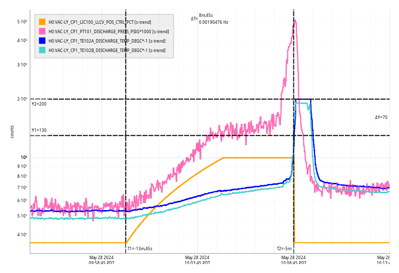
Tue May 28 10:08:45 2024 INFO: Fill completed in 8min 41secs
Travis confirmed a good fill curbside.
This morning Camilla and I started to realign the corner station HWS table to our new SR3 position. After doing some checks on table we went into the control room where we found out that we will be moving SR3 again, so we've deferred this work until we know that SR3 is in a final position. Below are links to procedures, some notes Camilla took, and other commentary to help us when we do this next.
T1700163 - Procedure to align with invac picos, but mostly only M1.
LLOalog59625 - LLO alignment using above procedure
Presentation slides on pico alignment with both M1 & M2
LHOalog62527 - April 2022 LHO alignment with these picos
Notes from today:
ITMX ALS beam was hitting top periscope mirror and missing bottom mirror. ITM ALS was hitting both mirrors but mis-centered on bottom periscope mirror.
Started looking at ITMX camera, removed both plates.
SR3 Yaw, old alignment -150, new alignment 120.
Checking beam on HWS using SR3:
Beam there at -150, Beam gone -190, -170 plateau/edge, -75 plateau/edge
Center between both plateau -120. Checked we could see ITMY HWS beam on camera here.
Went towards optimal SR3, SR3 Y at -60
Pico#7 M2. X more negative. Started at 0, went to -500, where our average pixel values back to plateau/ before clipping on other side.
SR3Y to -40
Pico#7 X —1500
SR3Y to -10
Pico#7 X —3090
Now have hard edge in left side of camera picture.
Moved #8 M1 from 0 to 500 in X. (Realized we meant to be moving M1 the whole time)
Reverted so all picos are 0,0. SR3 Y back to original +120.
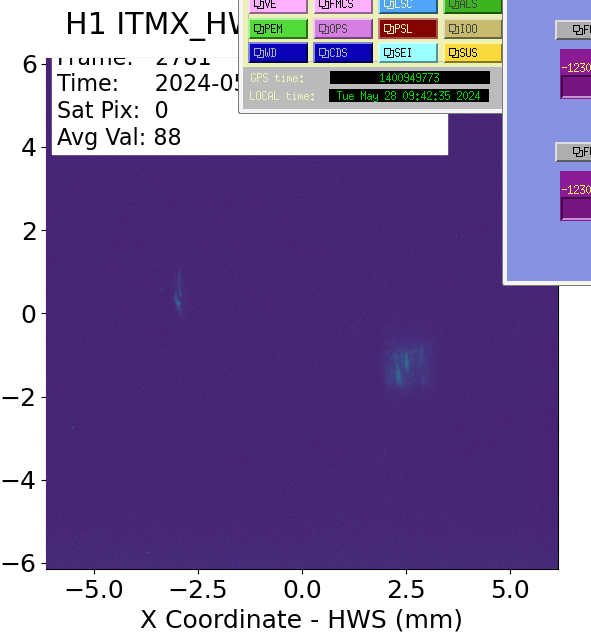
Can see some bright spots on the ITMX camera that remain when ITMX is misaligned (screenshot). We should check for on table beams getting to the camera, might need to add beam blocks. Also, seeing multiple point diffraction on the streamed image, this has been dust in the past so it might be a good time to check cleanliness on the optics while we are on table next.
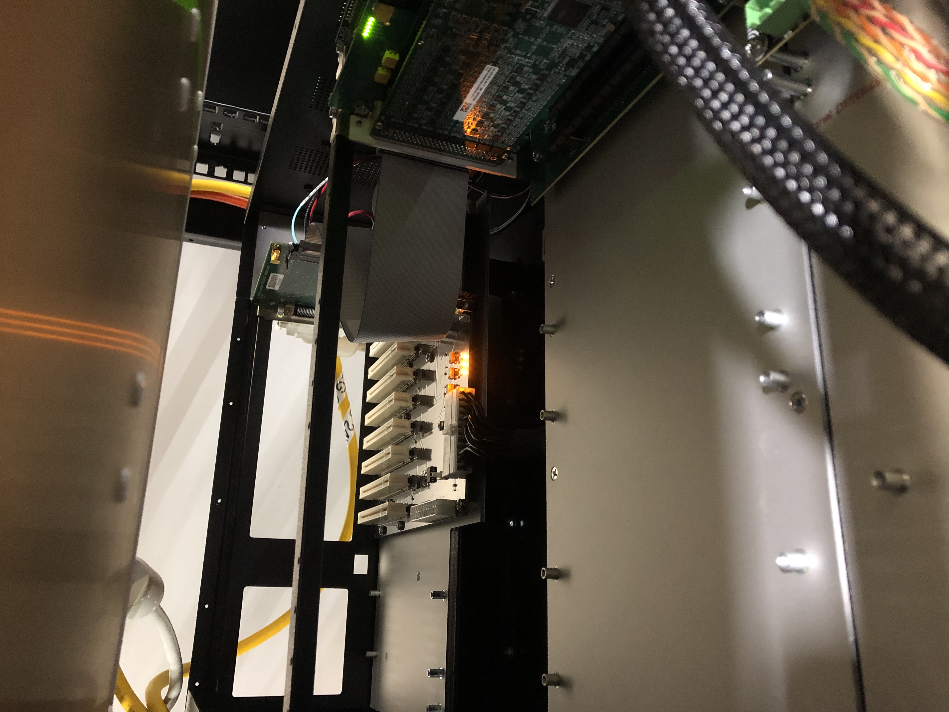
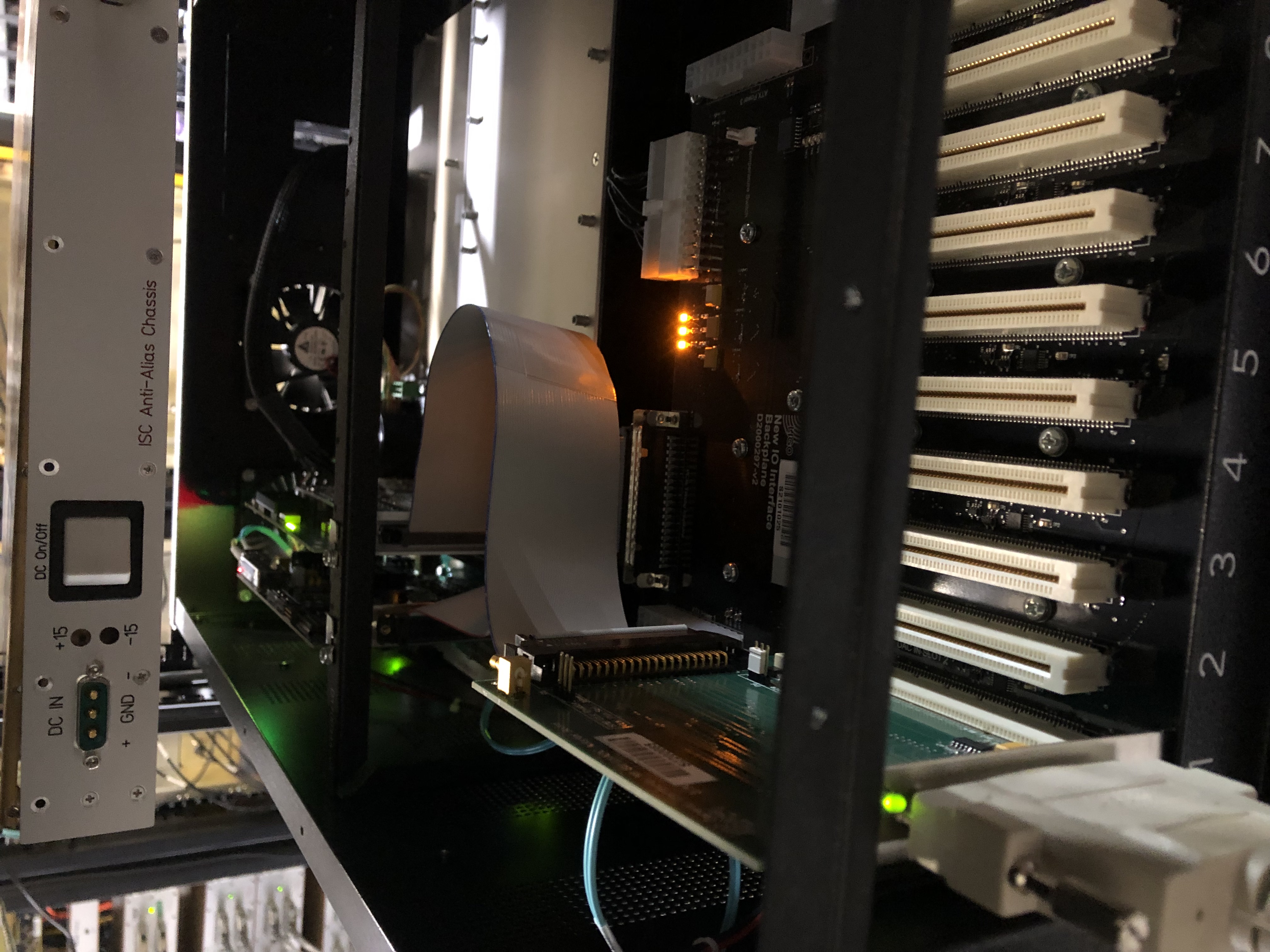
Pictures of the OMC IO Chassis.
DCC-D1301004 has been updated
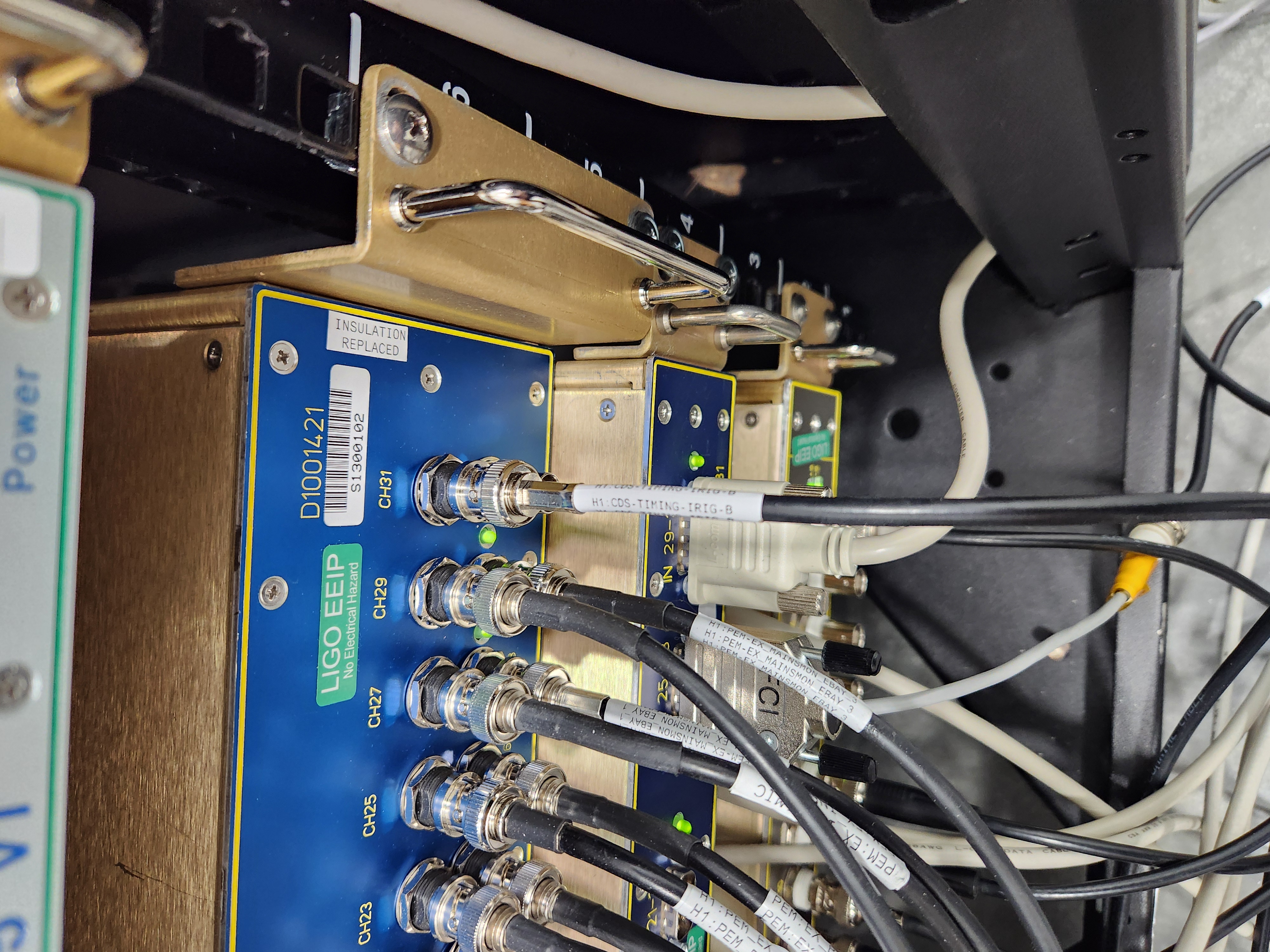
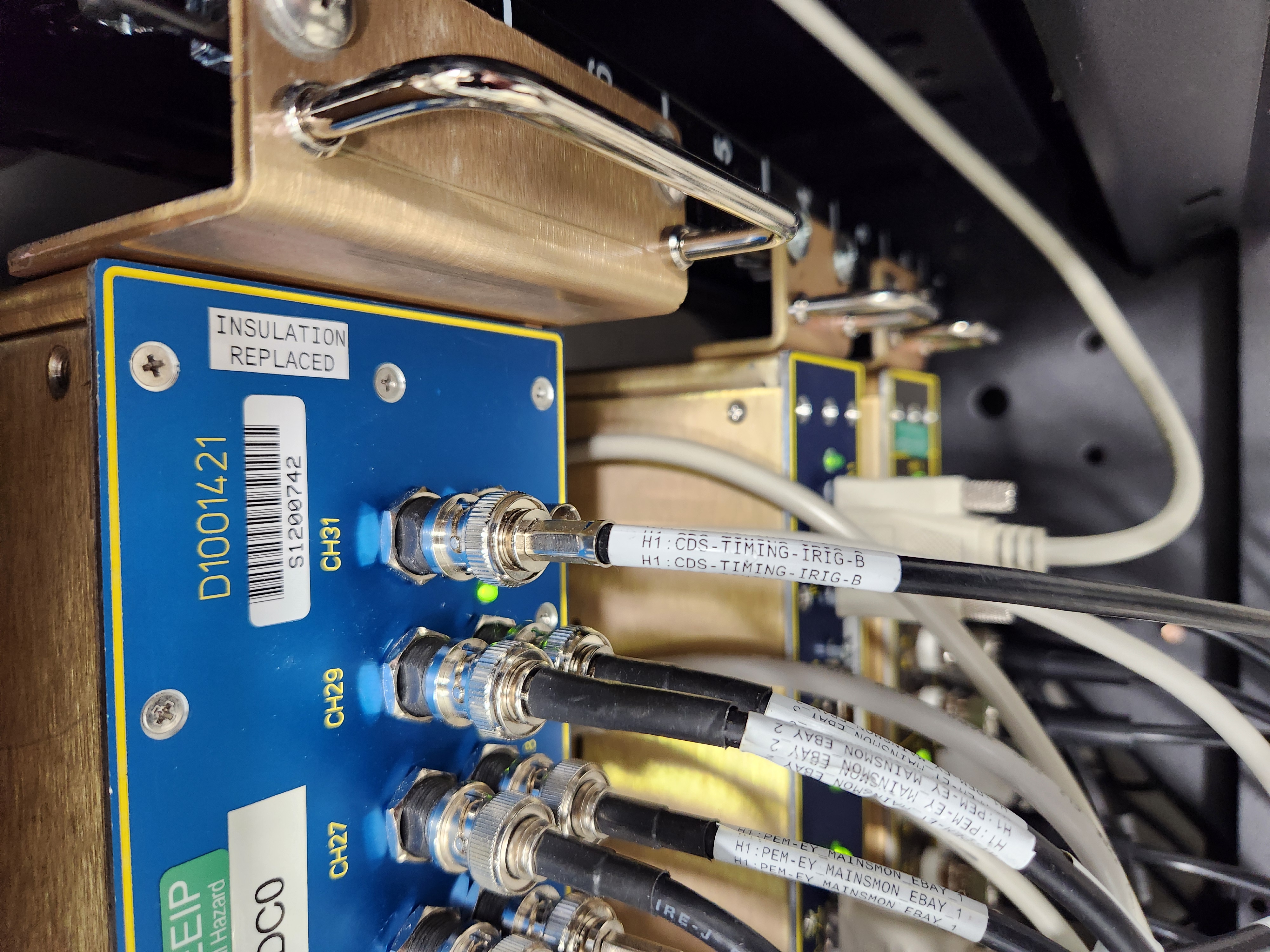
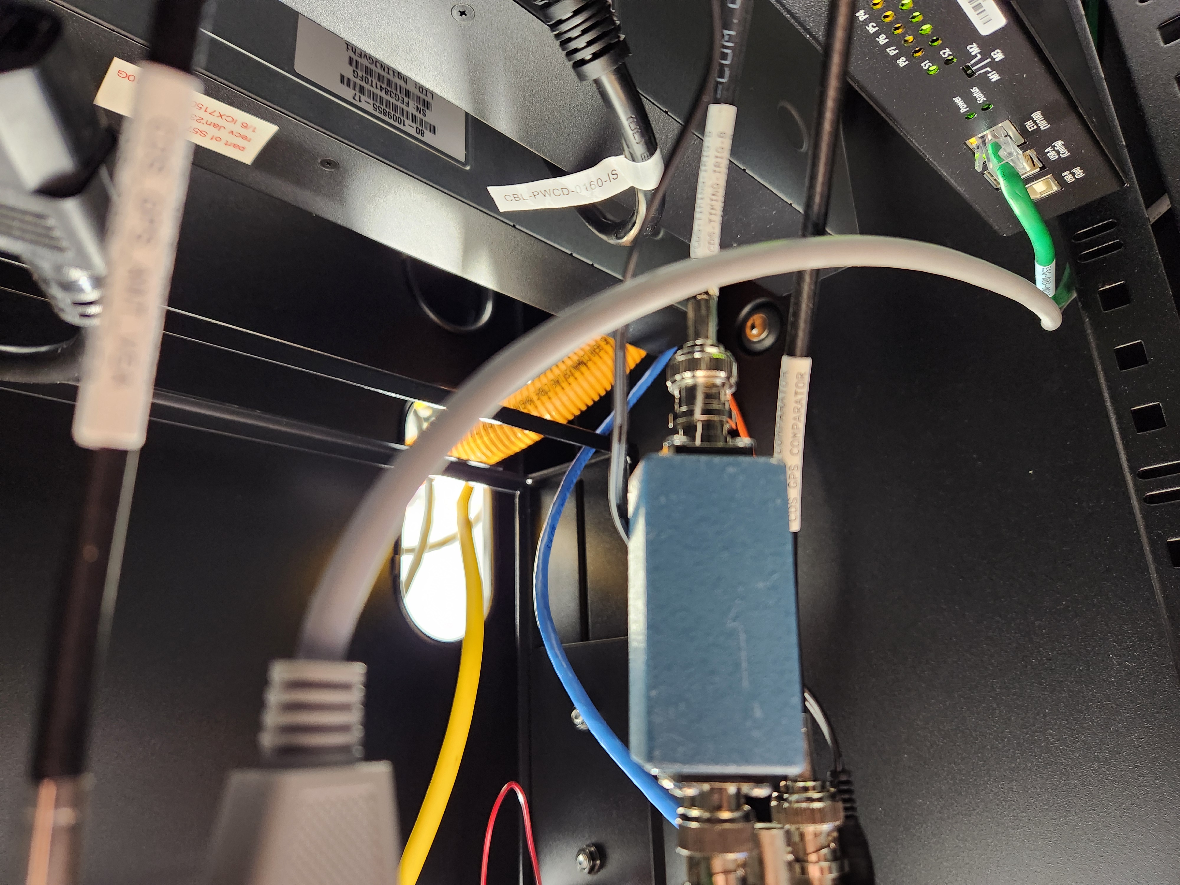
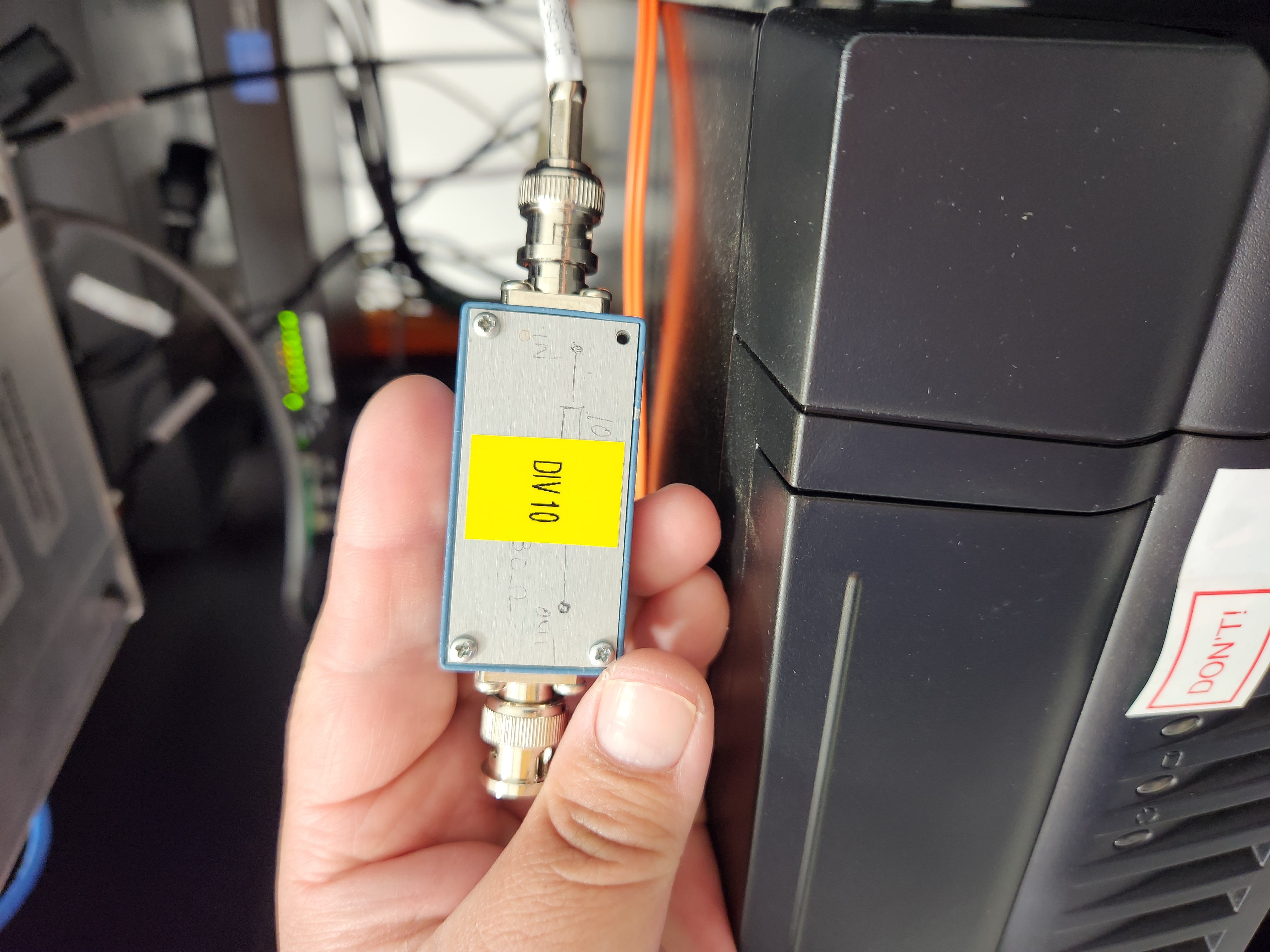
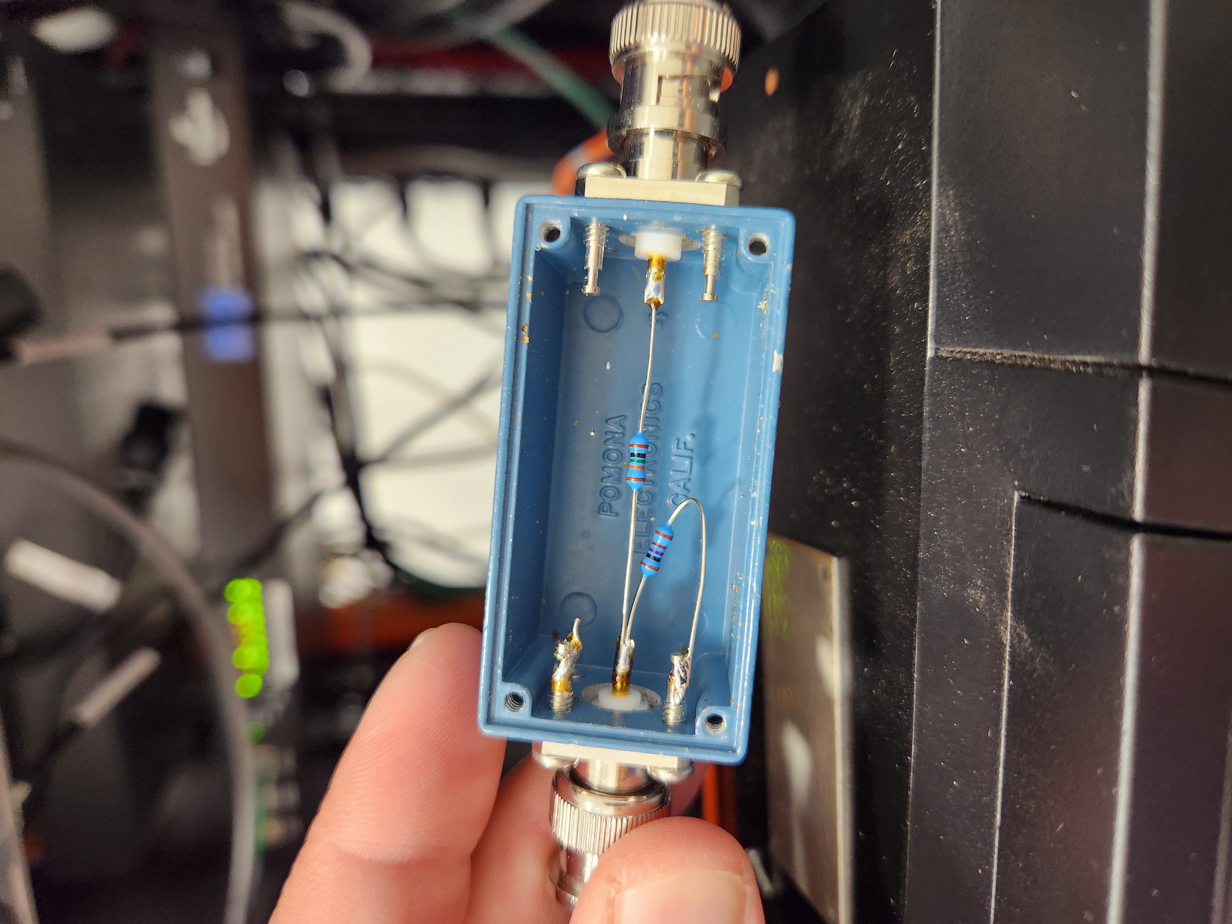
LLO noted a 10 Hz comb that was attributed to the IRIG B monitor channel at the end station connected to the PEM chassis. (https://alog.ligo-la.caltech.edu/aLOG/index.php?callRep=71217)
LHO has agreed to remove this signal for a week to see how it impacts our DARM signal.
EX and EY cables have been disconnected.
Disconnection times
| EX | GPS 1400946722 | 15:51:44 Tue 28 May 2024 UTC |
| EY | GPS 1400947702 | 16:08:04 Tue 28 May 2024 UTC |
I checked H1:CAL-PCALX_IRIGB_DQ at gps=1400946722 and H1:CAL-PCALY_IRIGB_DQ at gps=1400947702. From 10 seconds prior to the cable disconnection to 1 sec before the cable disconnection, IRIG-B code in these channels agreed with the time stamp after taking into account the leap second offset (18 sec currently).
Note that the offset is there because the IRIG-B output from the CNS-II witness GPS clock ignores leap seconds.
I fixed things in https://svn.ligo.caltech.edu/svn/aligocalibration/trunk/Common/Scripts/Timing/ so that they run in the control room with modern gpstime package and also the offset is not hard coded. I committed the changes.
Please reconnect the cable soon so we have independent witness signals of the time stamp. There could be a better implementation but we need the current ones until a proper fix is proposed, approved and implemented.
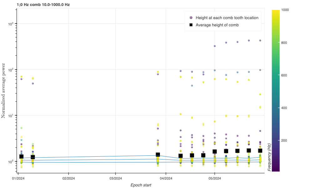
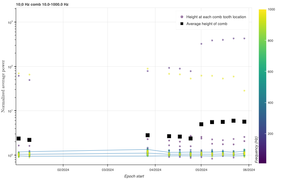
I have checked the weekly Fscans to look for similar 1 Hz and 10 Hz combs in the H1 data (which we haven't see in the H1 O4 data thus far), or any obvious changes in the H1 spectral artifacts occurring due to the configuration change May 28. I do not see any changes due to this configuration change. This may be because the coupling from the timing IRIG-B signal may be lower at LHO than it is at LLO. I do notice that there is some change around the beginning of May 2024 that the number of line artifacts seems to increase; this should be investigated further. Attached are two figures showing the trend of 1 Hz and 10 Hz comb, where the black points are the average comb power and colored points are the individual comb frequency power values; color of the individual points indicates the frequency. Note that there is no change in the last black data point (the only full-1-week Fscan so far).
The IRIGB cables at EX and EY have been reconnected (PEM AA Chassis CH31).
As per WP 11871 I updated the x509 certificates for the local ldap servers. This is regular maintenance and should not have been noticed by any users. I updated the secondary system first and found some puppet issues that I fixed before updating the other servers. This mainly involved putting the CA certificate chain in the certificate file for the slapd process.
FAMIS 20030
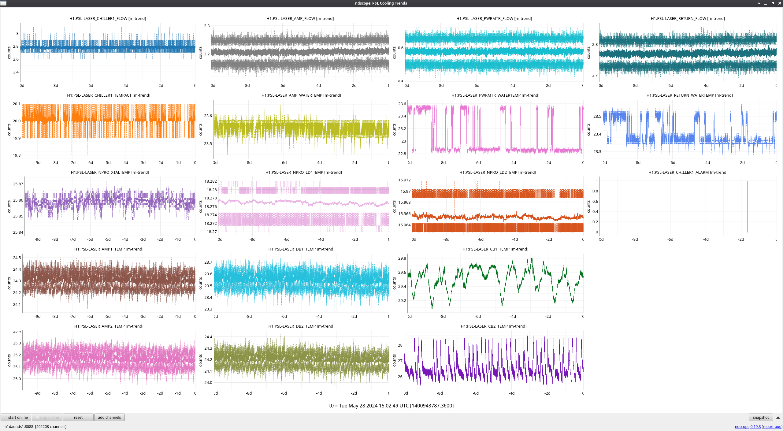
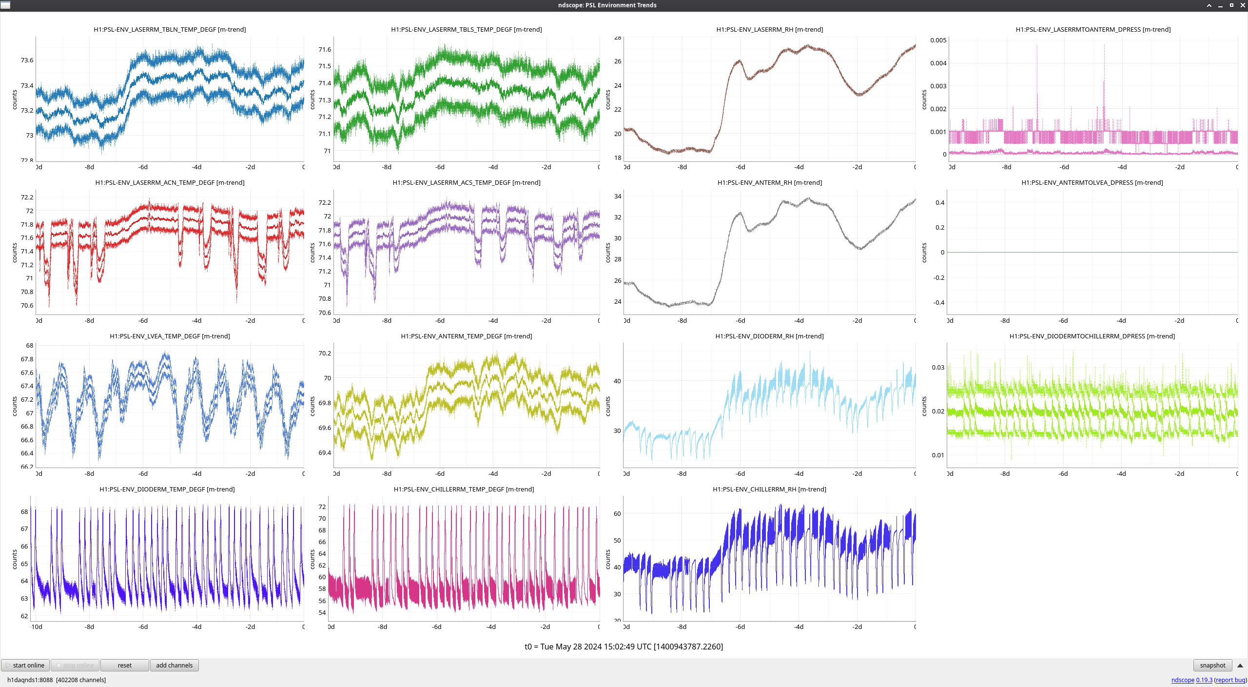
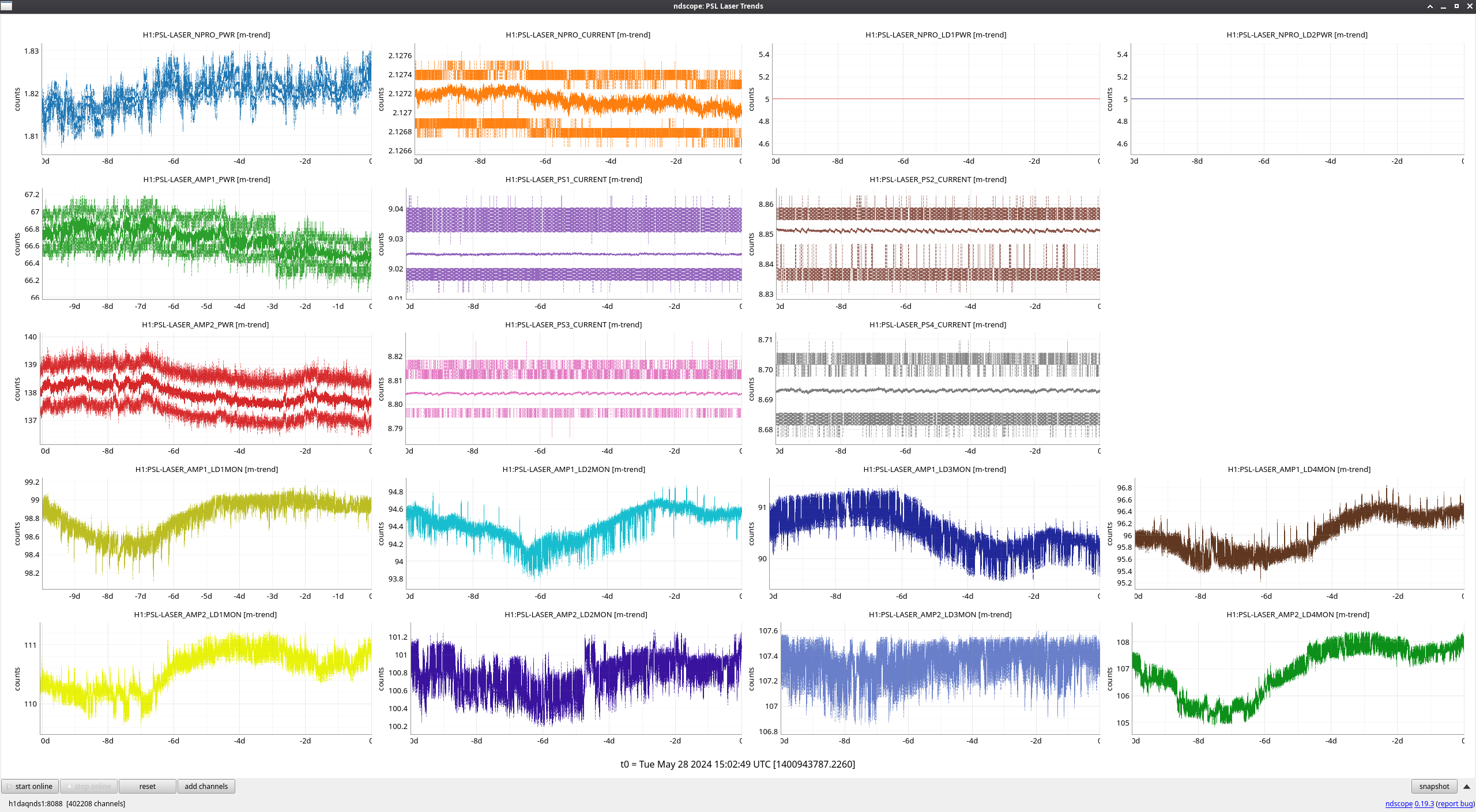
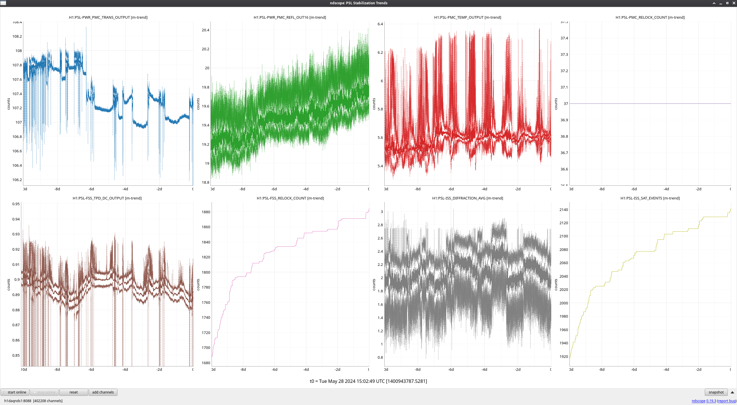
No major events this week other than the continued rise in PMC reflected power, which we plan to investigate more in-depth in the enclosure today.
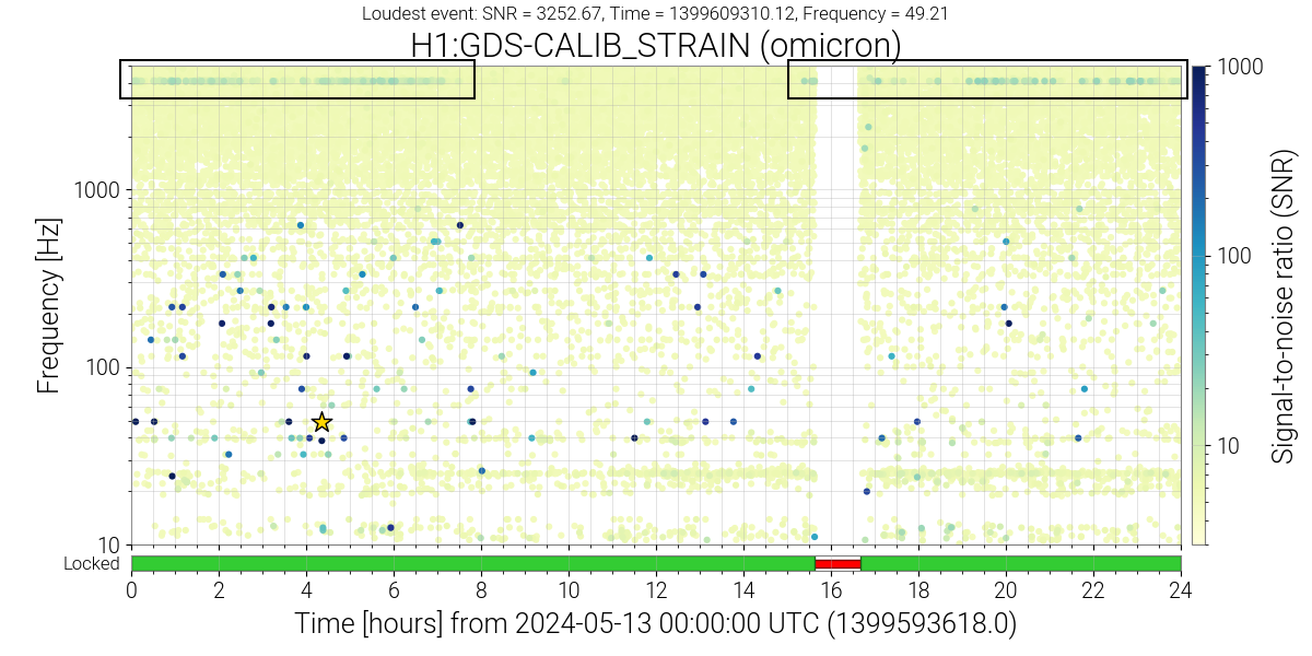
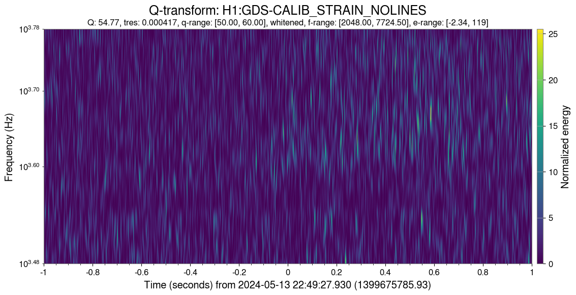
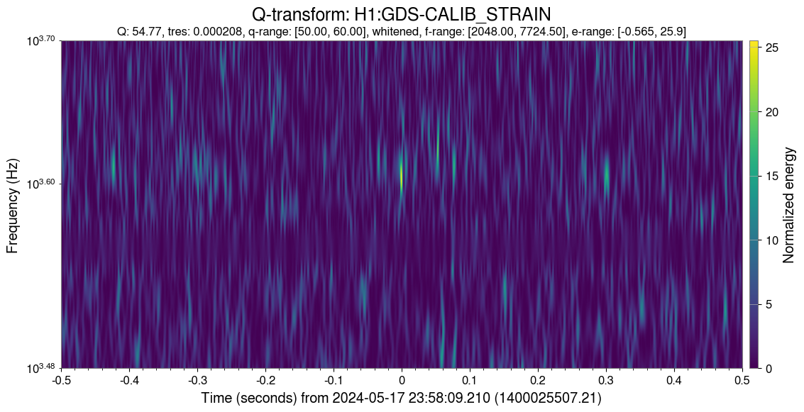
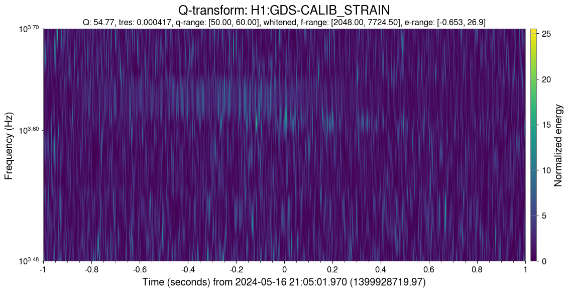
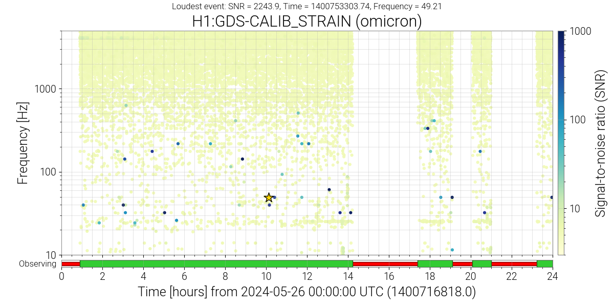
On May 13th (as part of my DQ shift), I noticed a line of 4kHz glitches in the glitchgram, and they have appeared every day since then. Checking the summary pages revealed they’ve been intermittently present since Apr 8, 2024 but not previously (I checked from Dec 1, 2023 onwards). Fig. 1 shows an example glitchgram from May 13th. Figs. 2-4 show Omegascans for some of these glitches. I also created a spreadsheet to characterize these glitches, and did not find any pattern or regularity to their appearance.
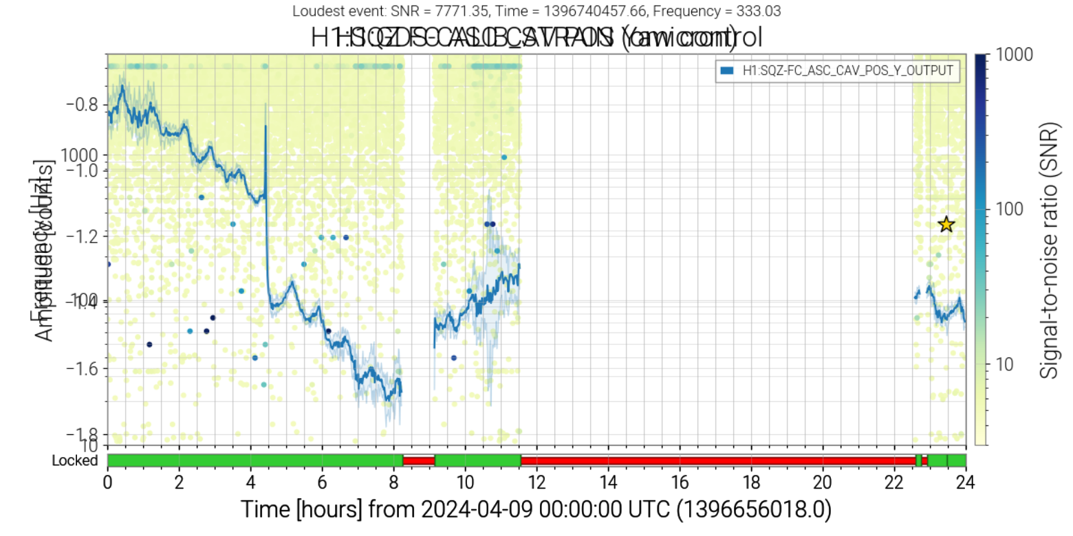
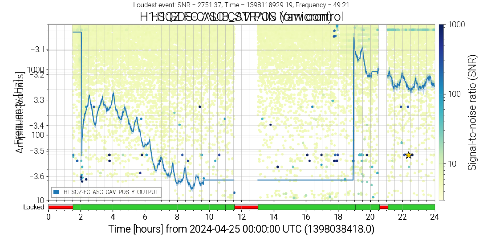
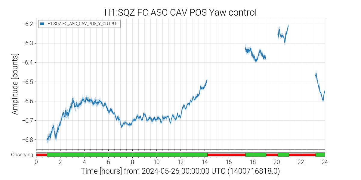
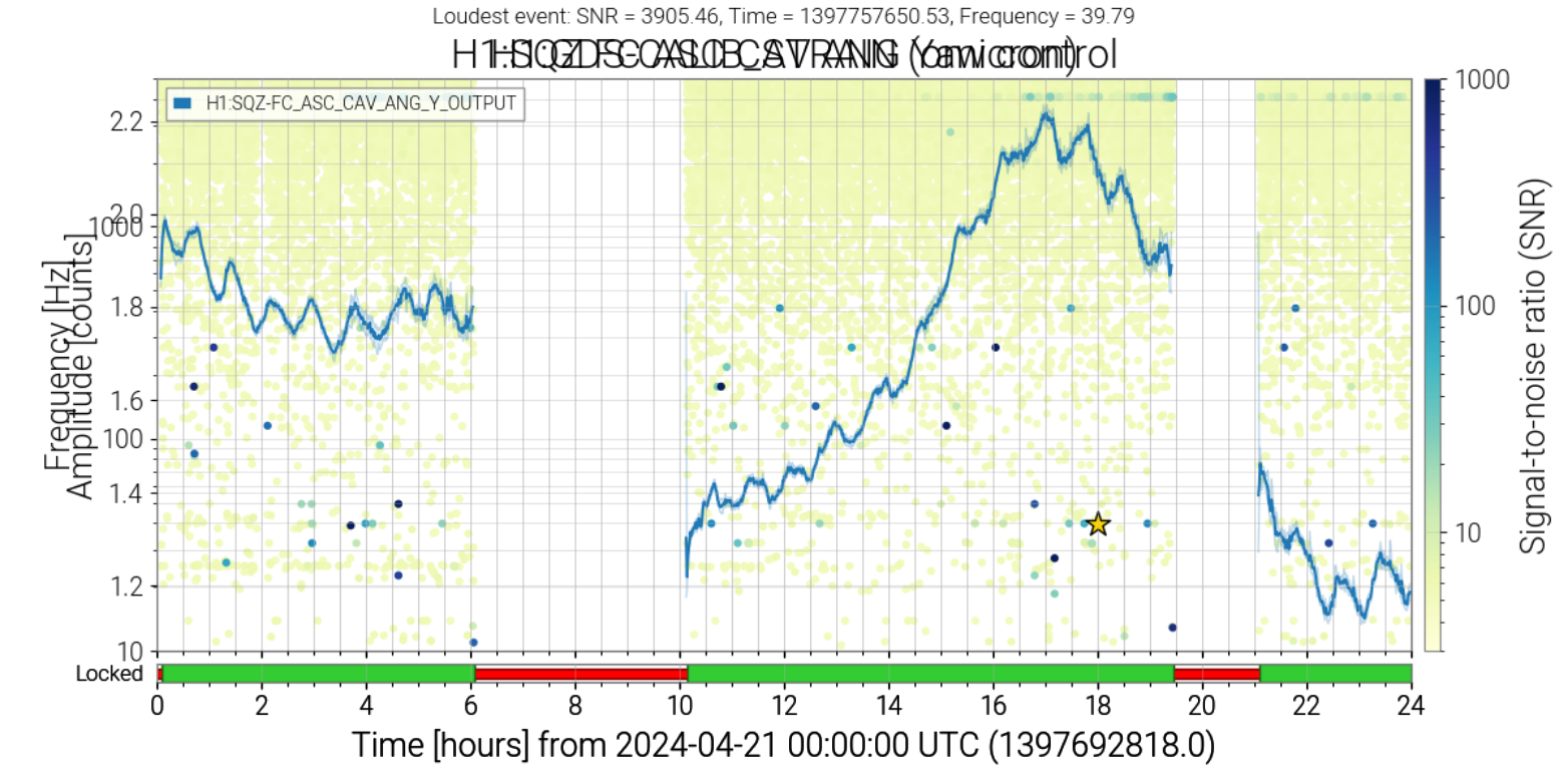
I checked the aLogs for possible sources and found the SQZ angle was being tuned around the time the glitches started (aLog). I then compared the timing of the glitches to the SQZ: FC ASC channels and found a correlation between the deviation in the output and the strength of the glitches. See Figs 5-7 for examples, as well as the spreadsheet. I will be meeting with the LSC fellows on Tuesday to discuss these.
Since May 24, the 4kHz glitches looked somewhat mitigated.
The correlation between the deviations of SQZ channels and the loud glitches at 4kHz has been hardly seen since May 24.
(The attachments are Omicron trigger plot and SQZ FC ASC channel on May 26)
There were SQZ commissioning works on May 24, and there are 2 alogs (alog 77980, alog 78033) related to SQZ alignment and the low frequency noises.
The 4kHz glitches are back on May 29, and the correlation between the glitches and the deviation of SQZ FC ASC channels looks apparent again.
JeffK, FranciscoL [LouisD remote]
Finished characterizing the spare OMC DCPD whitening chassis (D2200215), S2300002.
Noise is matching the expected performance. Transfer Functions look normal.
A fit of the TF data is pending and will be added as a comment.
Here are the zpk fits for the OMC DCPD data. The PDF Report is attached. OMC DCPD A: Whitening ON: zeros: [0.993694] Hz poles: [4.467514e+04 9.871288e+00] Hz Whitening OFF: zeros: [] Hz poles: [44628.188186] Hz OMC DCPD B: Whitening ON: zeros: [1.002049] Hz poles: [4.474433e+04 9.956902e+00] Hz Whitening OFF: zeros: [] Hz poles: [44711.662211] Hz The raw output is stored at [CalSVN]/trunk/Common/Electronics/H1/DCPDWhitening/OMCA/S2300002/20240523/Results/.