[Jenne, Corey, RyanS, Jane Glanzer]
After EE fininished cabling ISCT1 and IOT1, Keita and I put up laser barriers to make the South Bay of the LVEA local laser hazard ("bifurcated"), so that both tables can be opened at will.
Please pay attention to the signs on the laser barriers, and if the barriers are closed and / or the signs show Hazard, then wear laser safety goggles beyond the barriers.
The Vac team opened the gate valves, and we ran the baffle align scripts. After the baffle align scripts completed, I did not touch ITMX again.
Corey and I moved PR3 so that we could see beams on the cameras (we later reverted PR3's sliders), and moved ETMX and TMSX until we had nice TEM00 flashes. We were then able to lock it and run then offload the ETM_TMS_WFS.
With Xarm nicely aligned and PR3's sliders reverted, we had great transmission on ALSX and a familiar looking spot on the camera. However we didn't see anything on the Yarm PD or camera. So, I moved the BS until I could see something (also having increased the exposure of the camera so we could see the straight leakage beam), and then moved ETMY until we started to get flashes. I aligned ETMY and TMSY until we could hold lock on TEM00, and moved the BS until we had ~max transmission on ALSY's transmission PD. We then ran then offload the yarm's ETM_TMS_WFS.
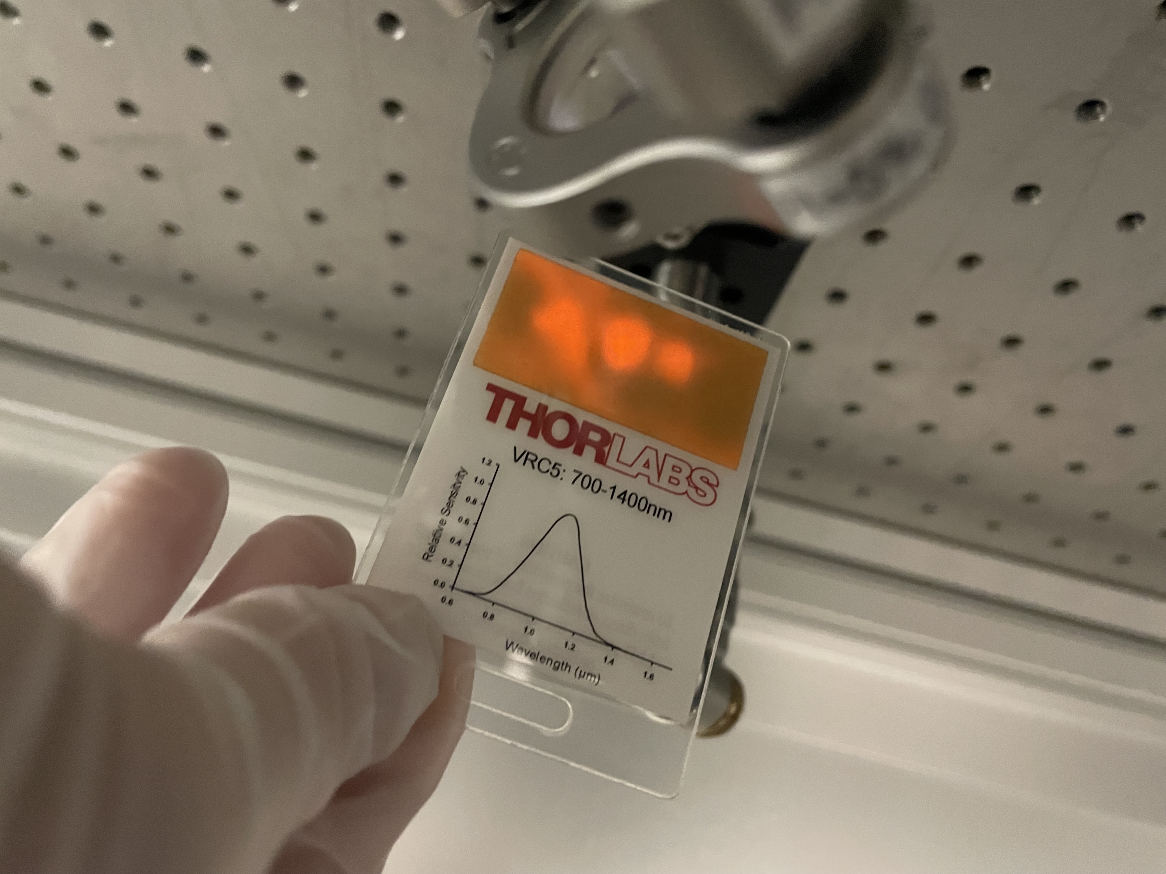
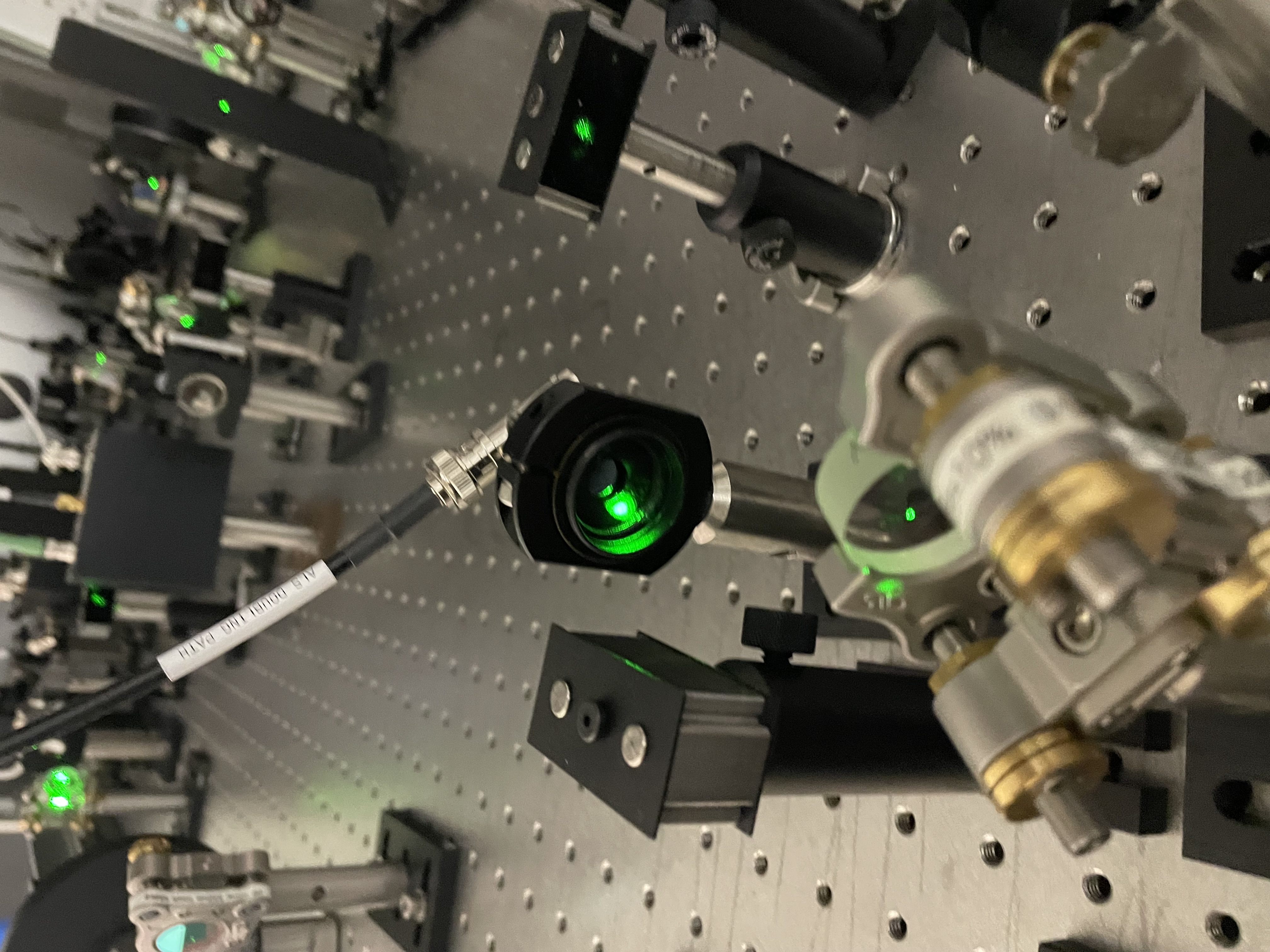
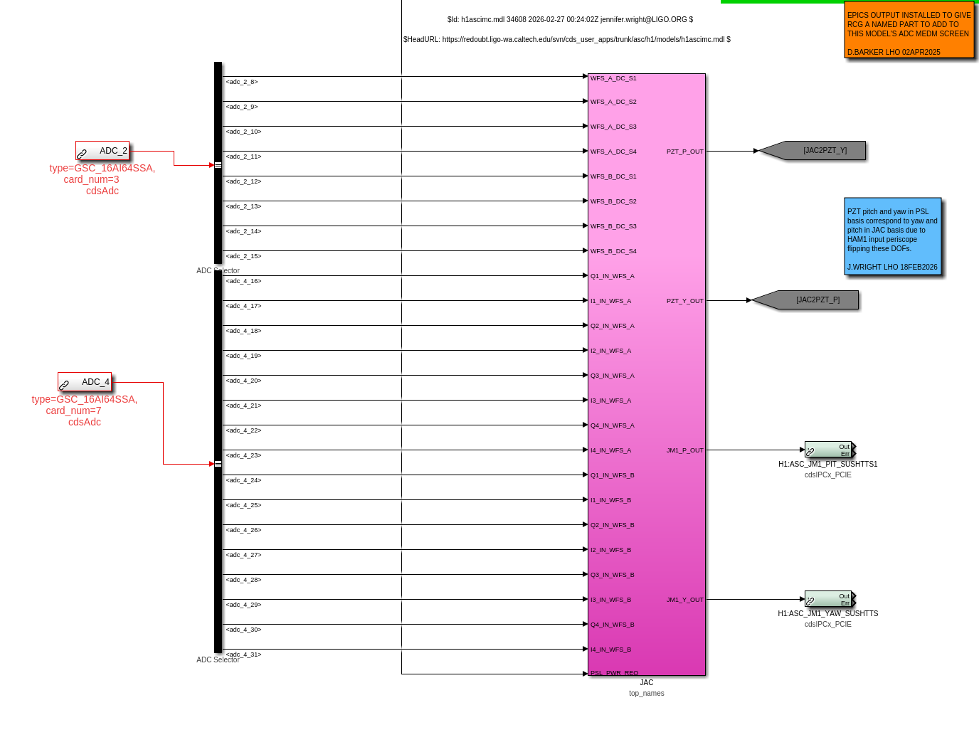
I then (since HAM1 is at much lower pressure than 10 mTorr) opened up the ALS light pipe, and went to check that the alignment on the table looked "reasonable". Indeed, it looks reasonable, in that the PSL beam seems to go nicely through the SHG and is roughly centered on downstream optics. However, we don't have good beatnotes. I had a quick look at the beams headed toward the beatnote PDs, and at least one is easy to see that there are 2 distinct beams headed toward the PD. I don't recall on the top of my head if this is the Diff beatnote though; if it is, then it depends on the BS alignment, so we likely want to hold off on doing any on-table alignment until we have a better idea of the BS alignment relative to the ITMs.
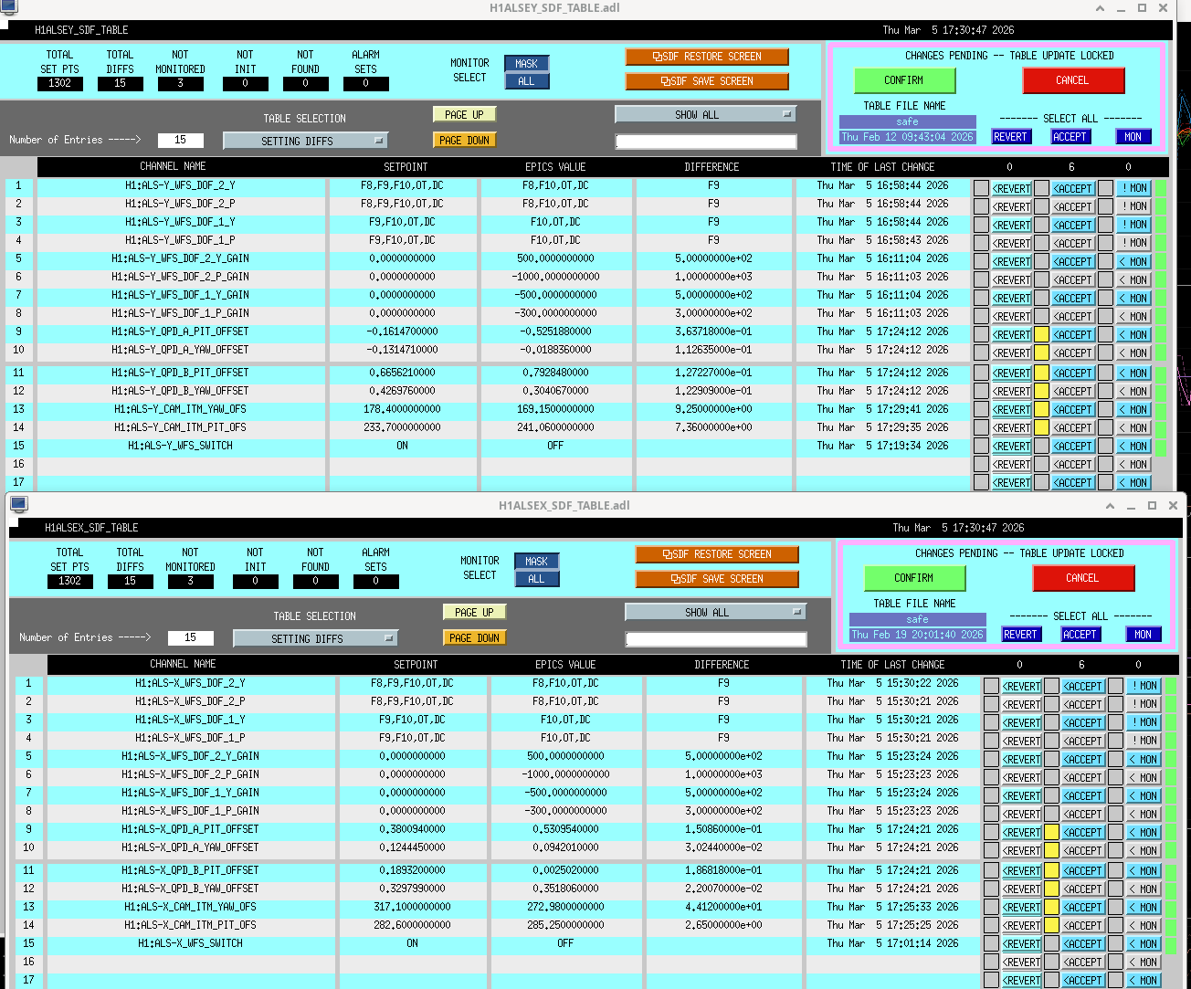
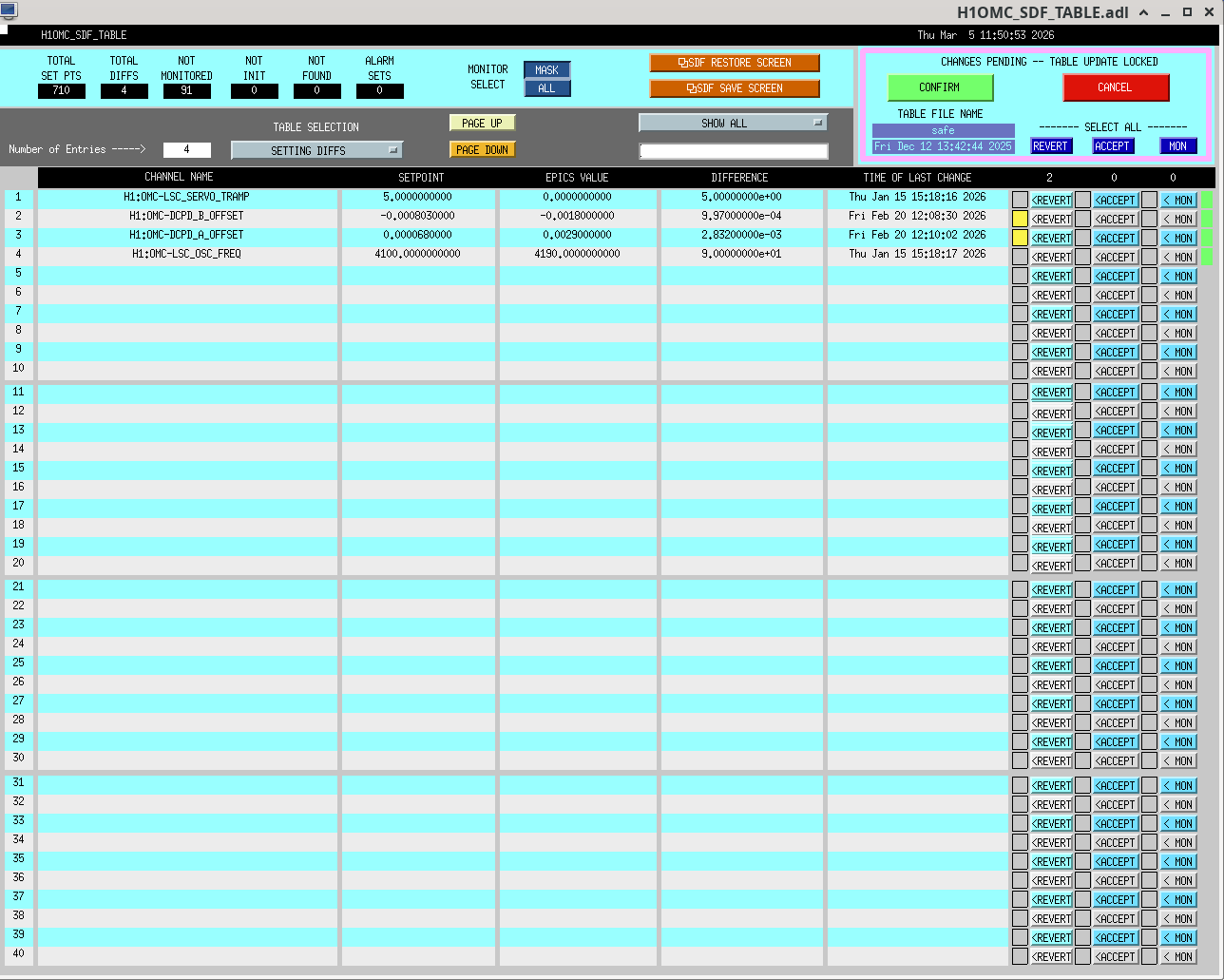
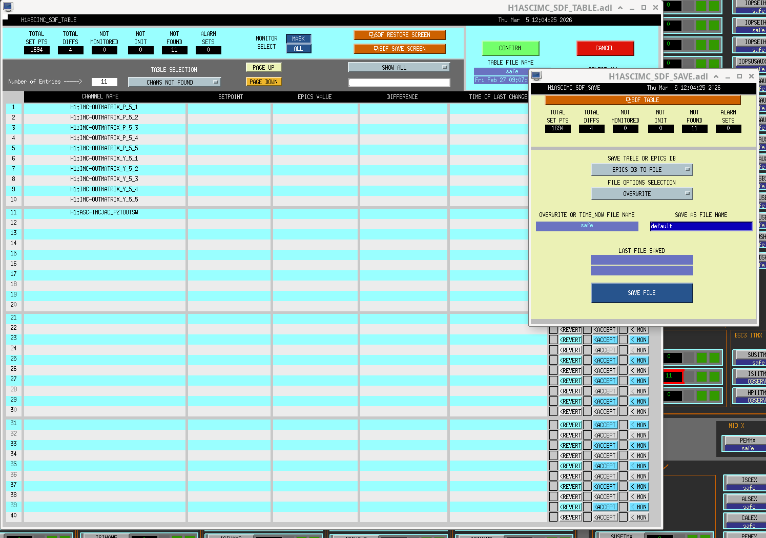
At Sheila's suggestion, I also reset the green initial alignment references (SDF table attached just before accepting them), so that we have an easier time coming back to where we are now. As usual, we'll have to re-reset them after we achieve full 2W lock.
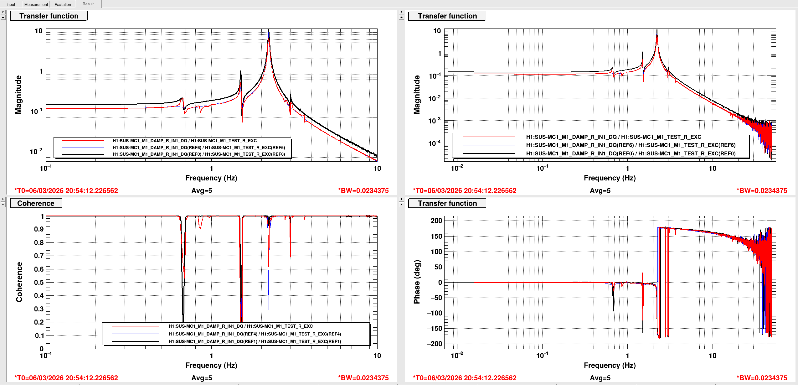
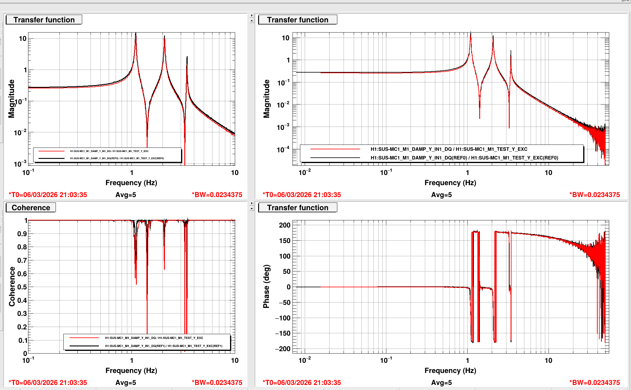
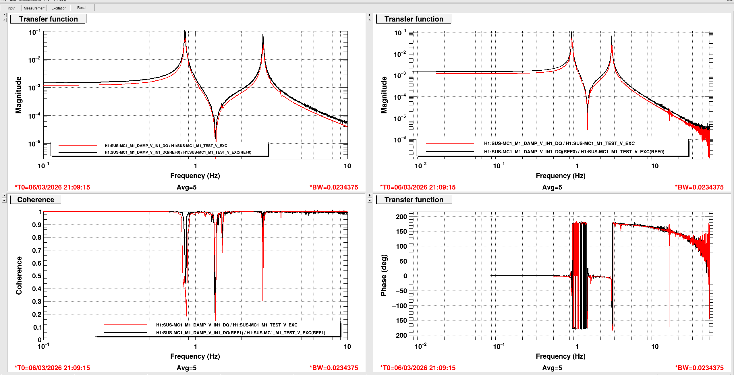
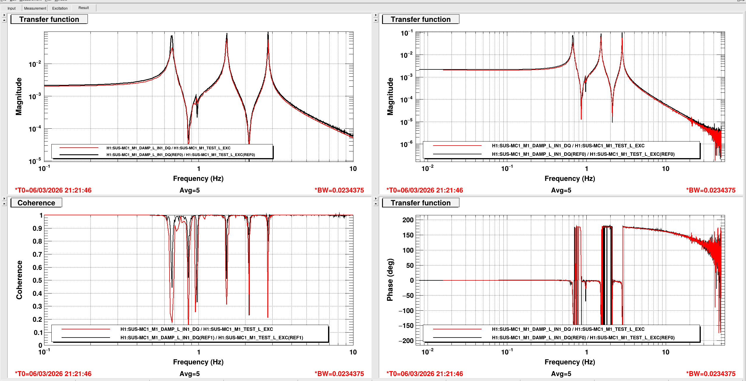
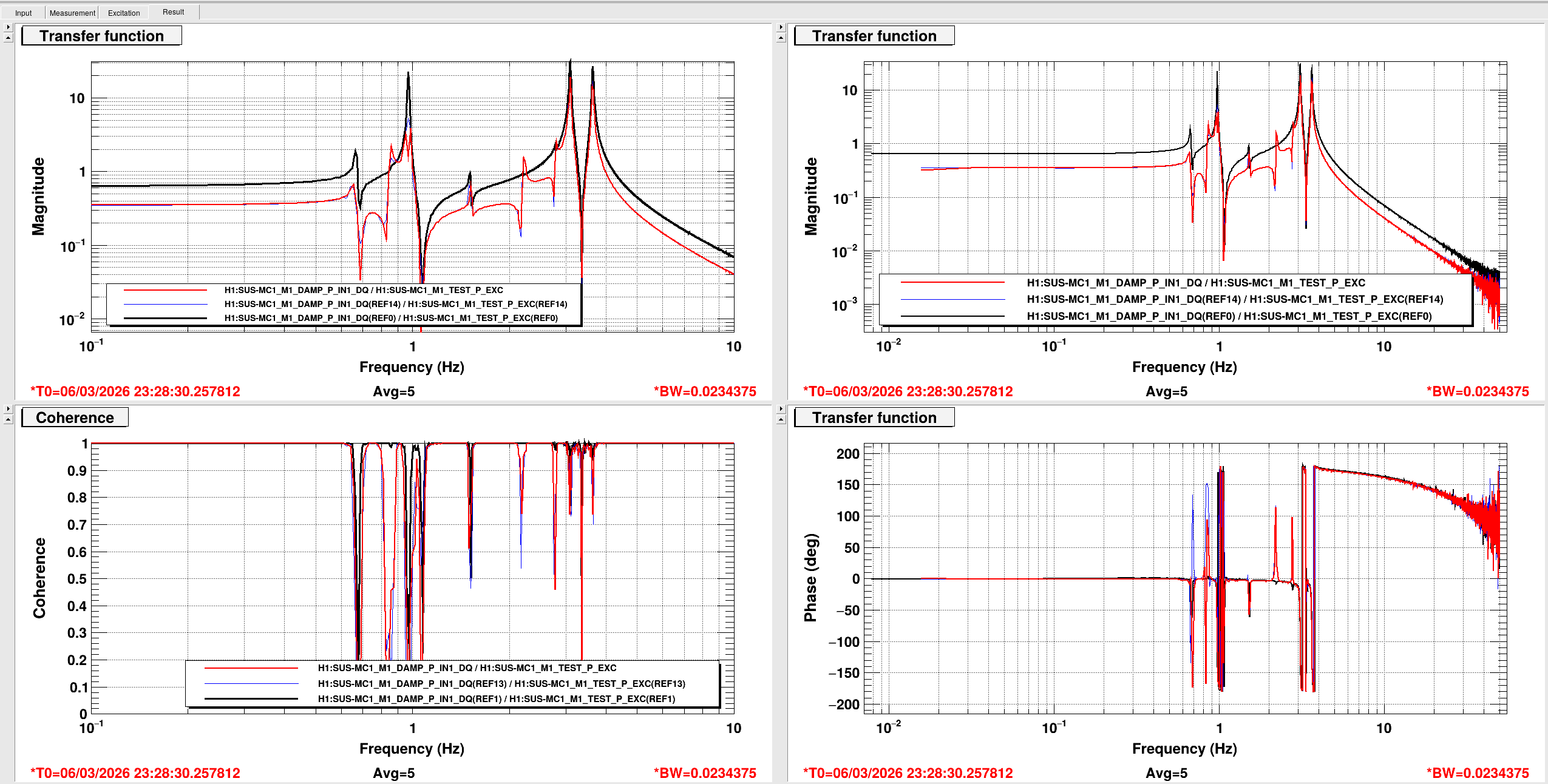
In summary: ITMs were set with the BafflePD script. Green ETM_TMS WFS were run and offloaded. Nothing on IST1 was touched (yet), but it's clear that we'll likely need to do some on-table alignment.
Proposed next steps: Check BS alignment by looking at MICH (so, after JAC is locked, then IMC locked, then XarmIR aligned). Then, consider aligning the ISTC1 beatnotes. Then, lock the whole IFO!