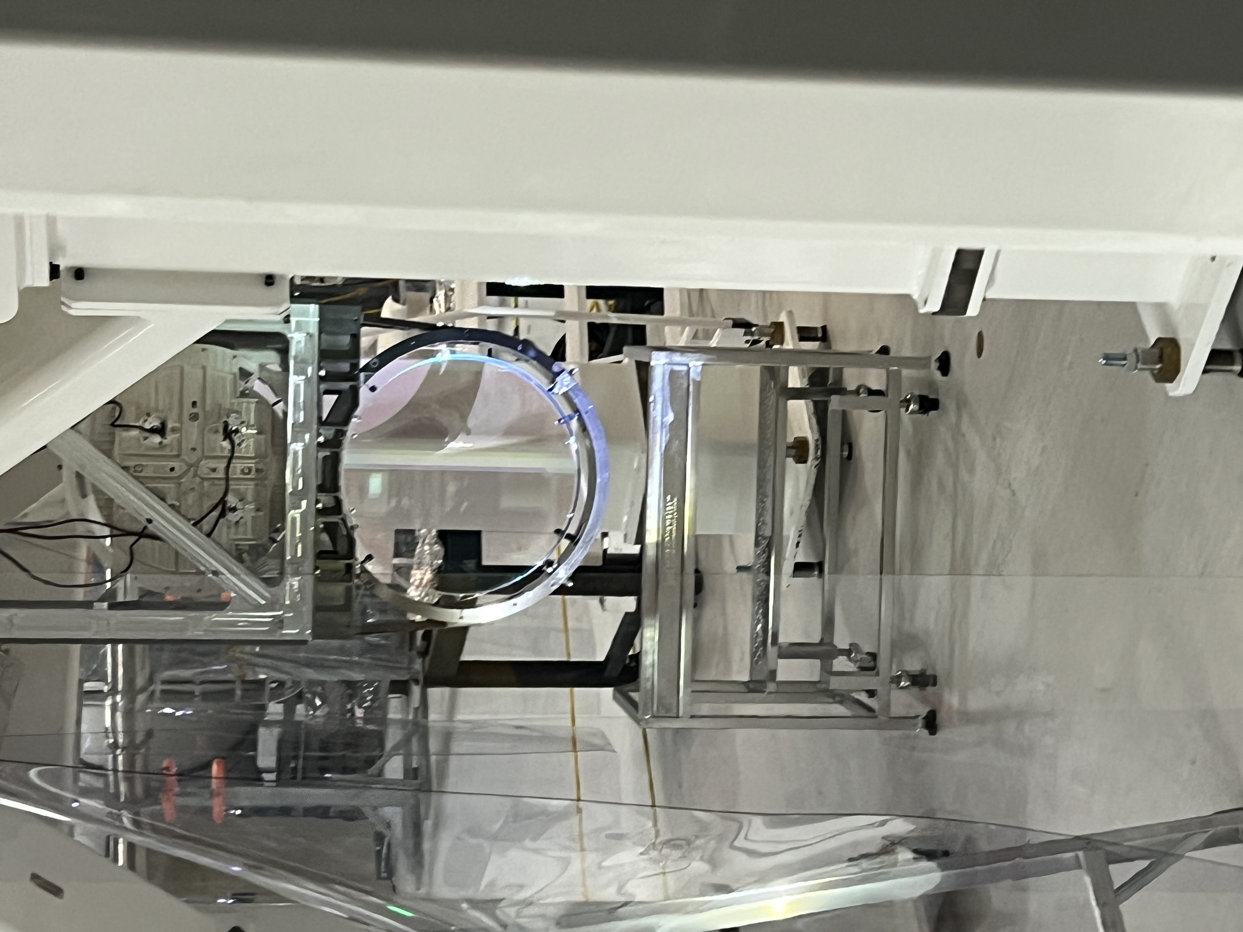
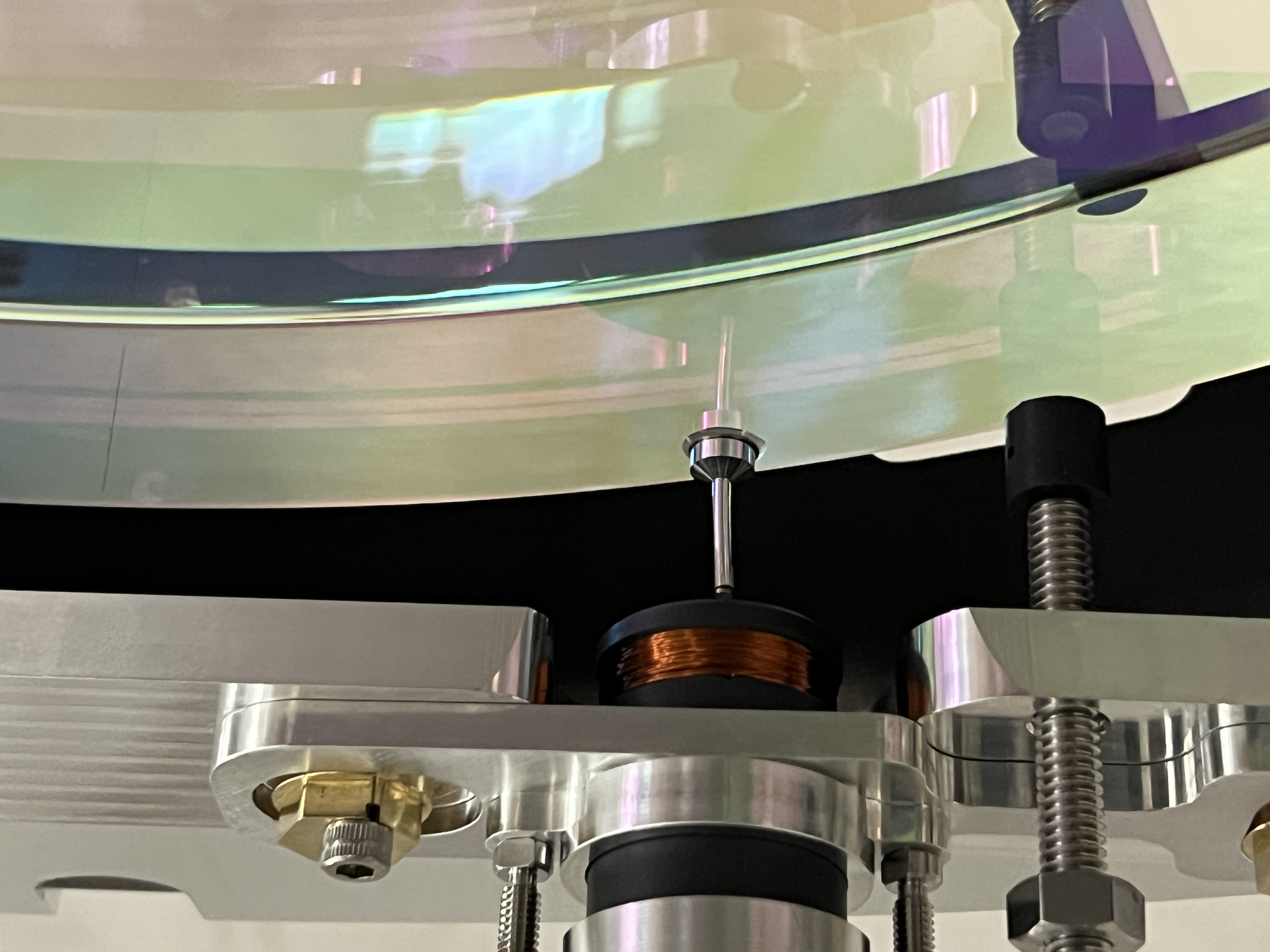
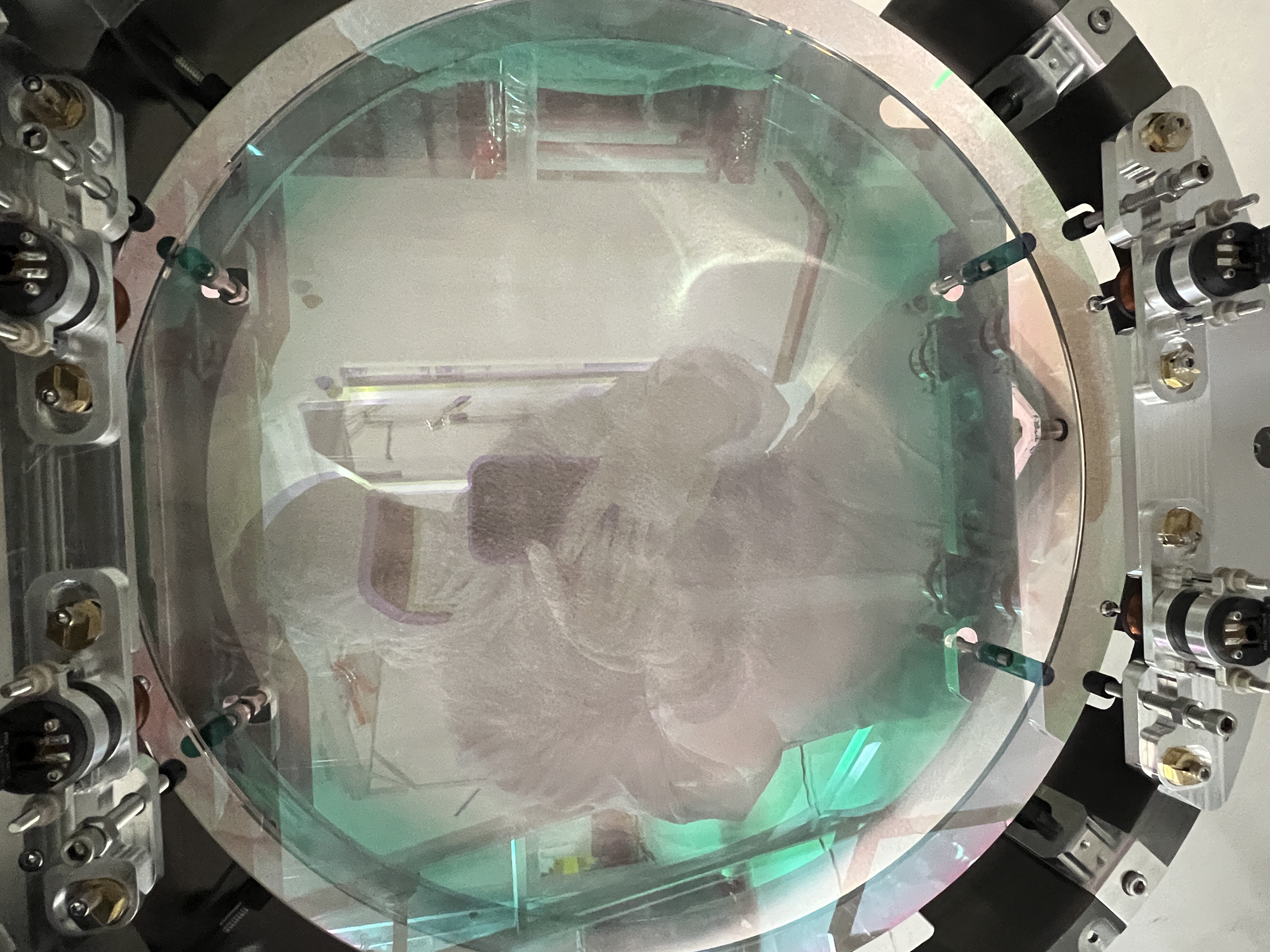
(Betsy, Jason, Oli)
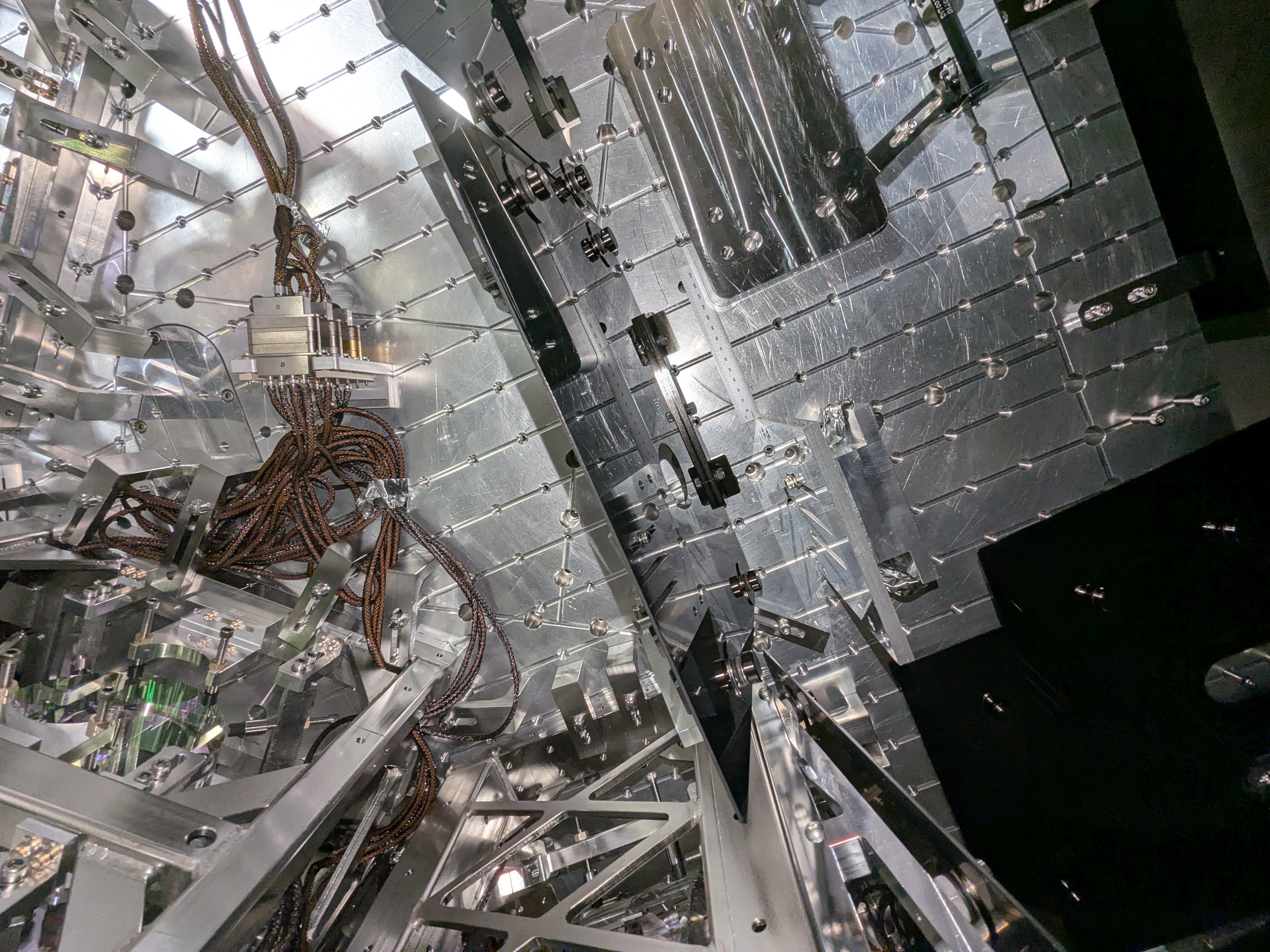
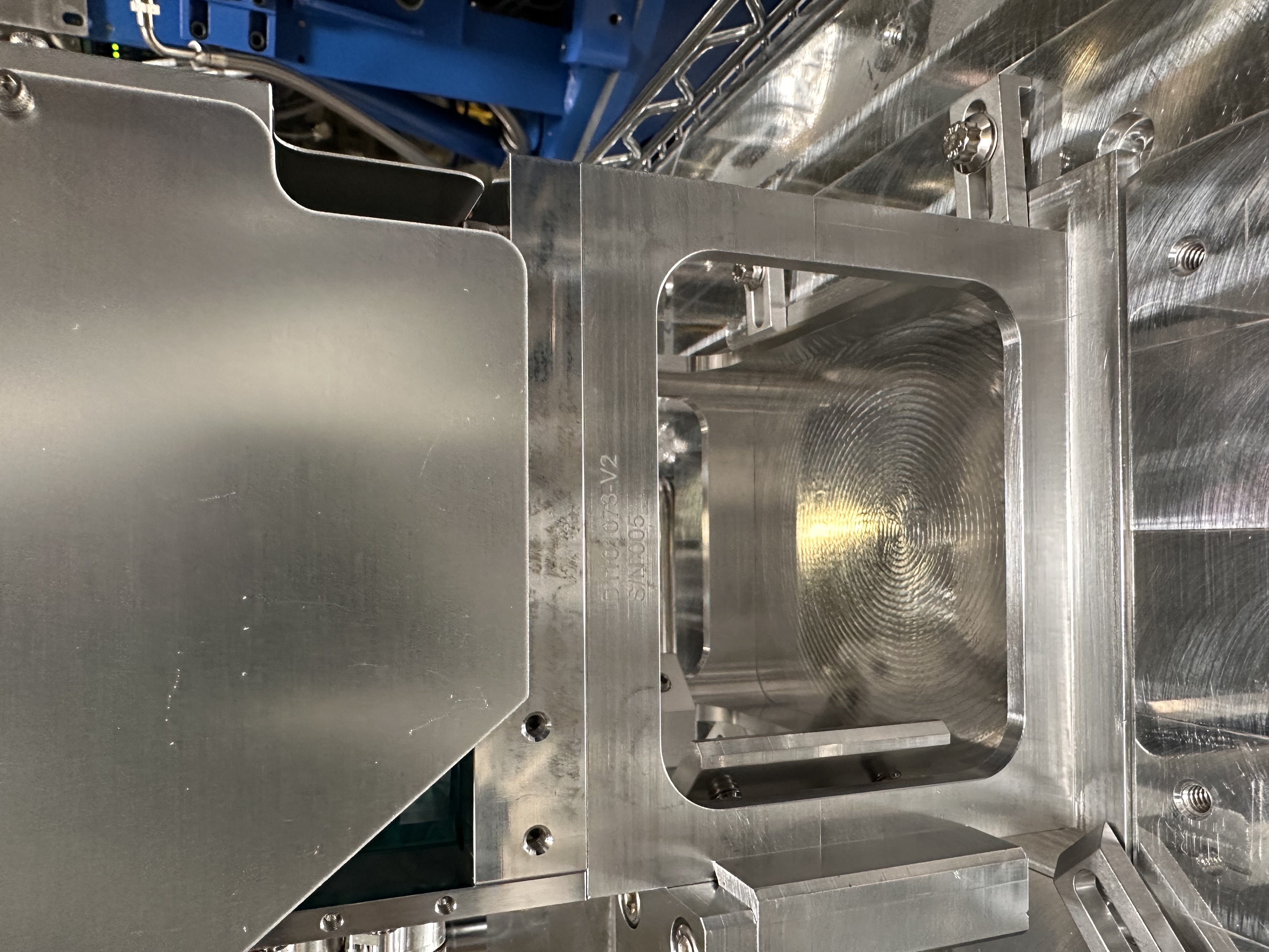
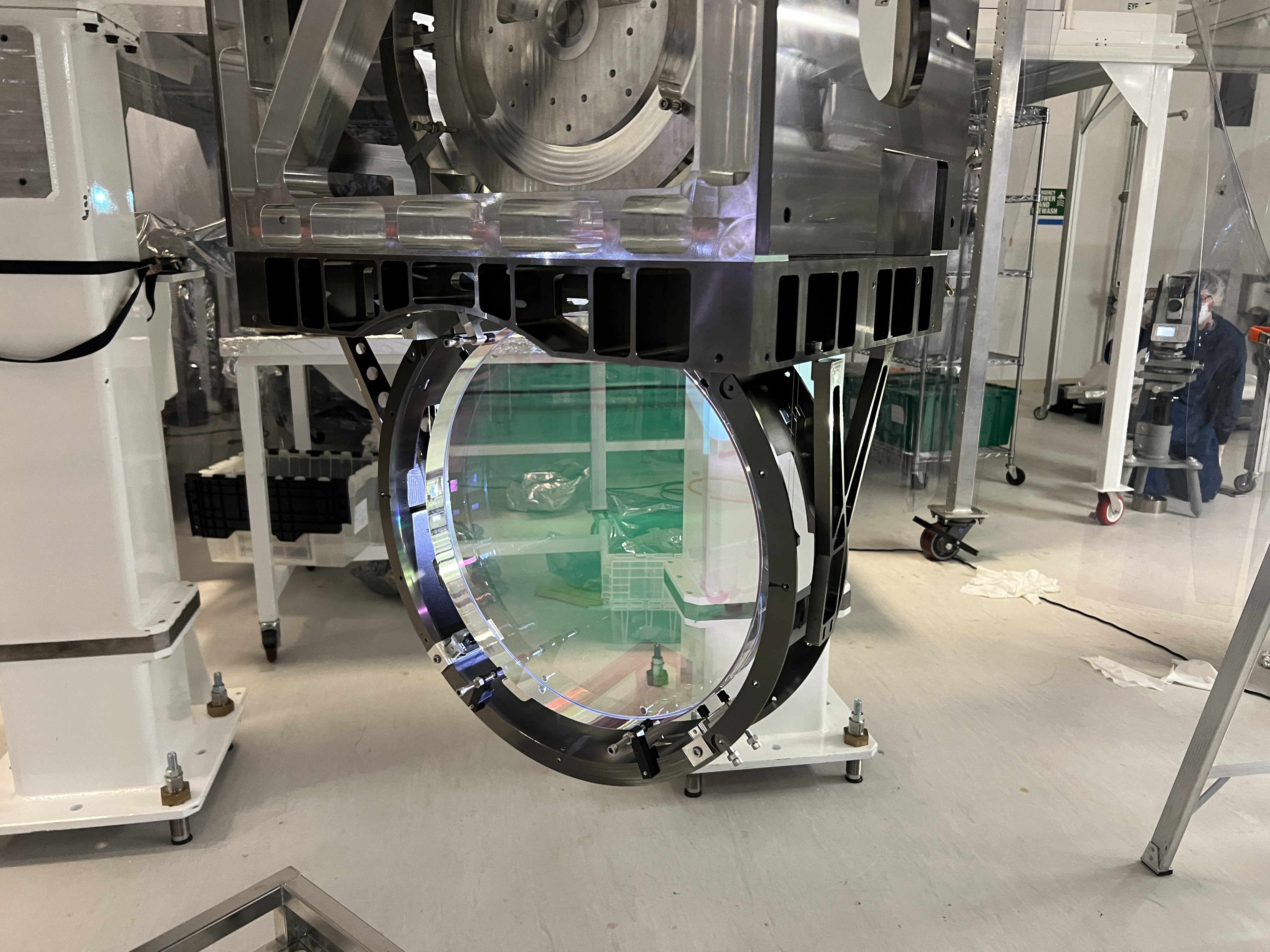
Today Jason setup to see Pitch and Yaw of the BBS in the suspension cage on the cartridge. We were a ways off in Yaw and some Pitch. I spent a few hours walking YAW but the mechanics are rough. 5 bolts lock down the whole Top Blade assy and then you can use a push or a pull screw to pivot the whole Top Blade mechanism. Repeat for the second Top Stage blade assy. Of course when you pop the 5 locking screw the entire chain sags and grounds on stops yeilding confusing beams to look at. So a few iteration of this and that got us kinda no where. Part way thru I discovered that the push/pull thingy was totally out of range on both. No idea why. So back to starting over tomorrow and maybe trying to go around this "yaw" adjustment and just push the stages in the mounting slop or something.
Seems like I wrote this alog 10 years ago. Probably did since the mechanics from the BS are the same and we struggled with them at that time too. Will need to read back and also check how LLO faired with this.
Meanwhile, Oli and I also struggled to get Pit damping working so a few hours of parallel brain straining on that, swapping out the quad cable and it seems to be working. Weird tho because this is the same cable we used on the BS just a couple weeks earlier.
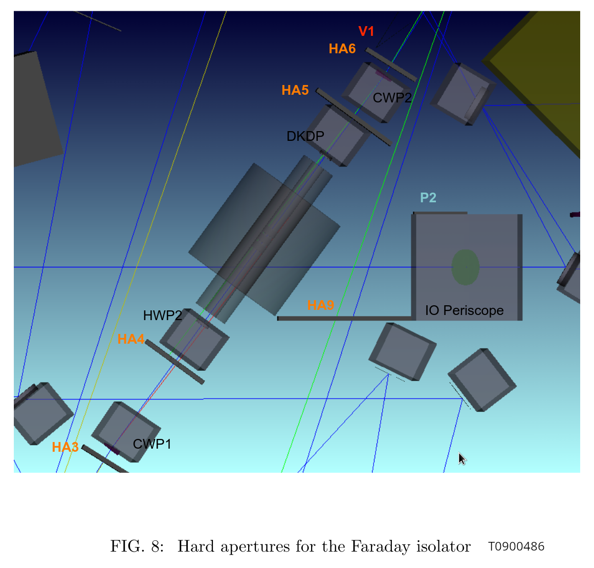
(I learned from T0900486 "IO Stray Light Analysis and Baffle Design" that the IFI input baffle is called HA3, IFI output baffle is HA6, the baffle right in front of IM4 is actually supposed to be a pair of HA12-a and HA12-b but there's only one baffle which I suppose is HA12-a, two-hole baffle for ISS array is HA11, and the last IFO REFL before the beam leaves HAM2 is HA13.)
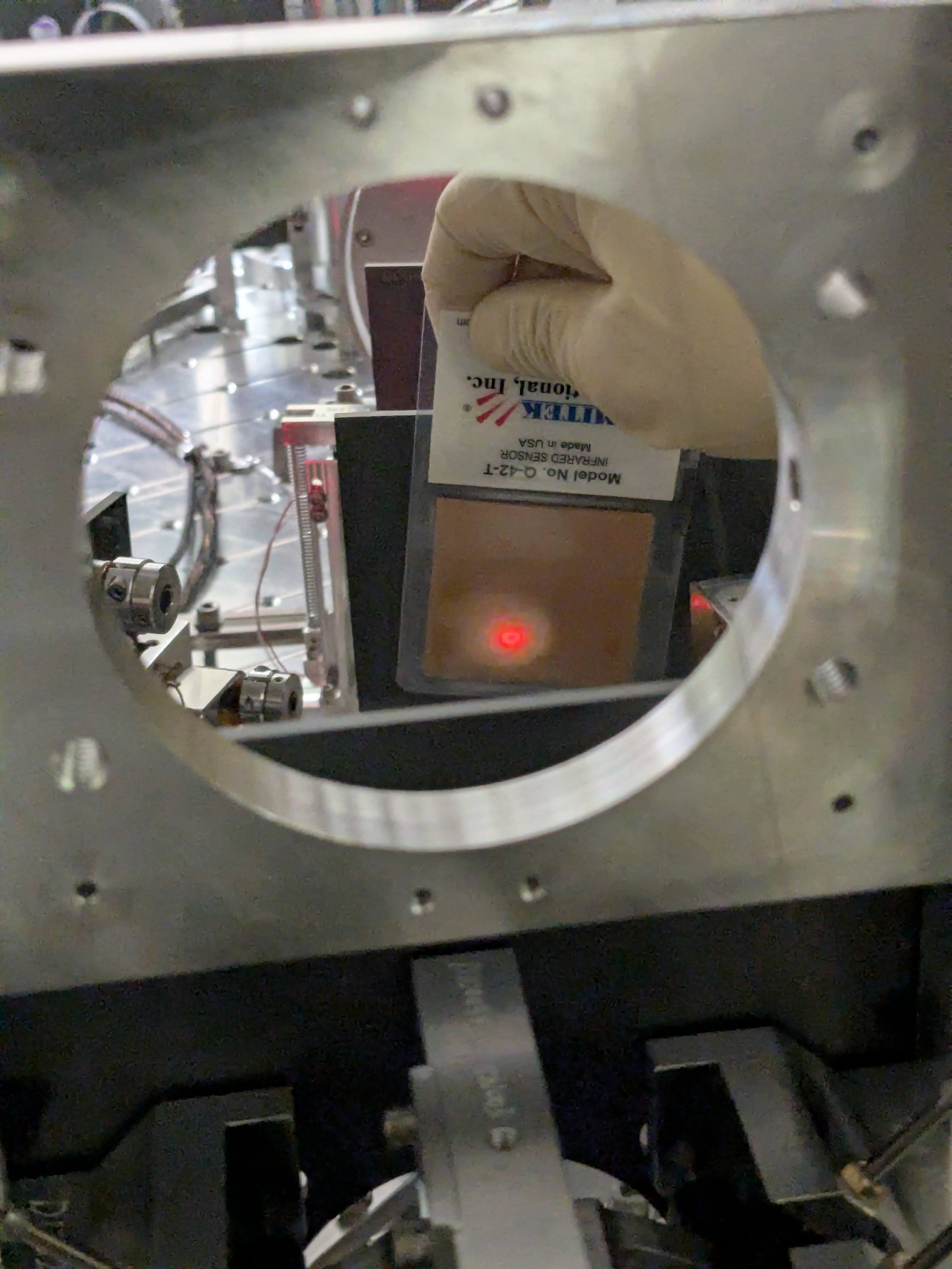
The beam spot on this baffle was OK before we did anything to IM1 on Tuesday (IFIinput_before.jpg). It's low and toward +X, but nowhere near clipping.
This baffle is right in front of the calcite wedge that deflects the IFO REFL beam away from the incoming beam path from IM2 (HA3_calcite_wedge.png). The lever arm from the wedge to the baffle looks to be an inch or so at most. Hard to imagine that the REFL is clipped while forward going beam is not, but the scattering goes away when I block the beam between PRM and IM4.
The reported "IFO REFL beam clipping" on this baffle is either because the PRM is not retroreflecting, or maybe it's some kind of ghost beam produced from the PRM reflection somewhere.
If we establish that the main IFO refl is NOT clipped when PRM retroreflects, we don't have to worry about this baffle too much (though ghost beam is still a problem).
We will have to bring a card with a hole to make sure that the beam is retroreflected as good as we can.
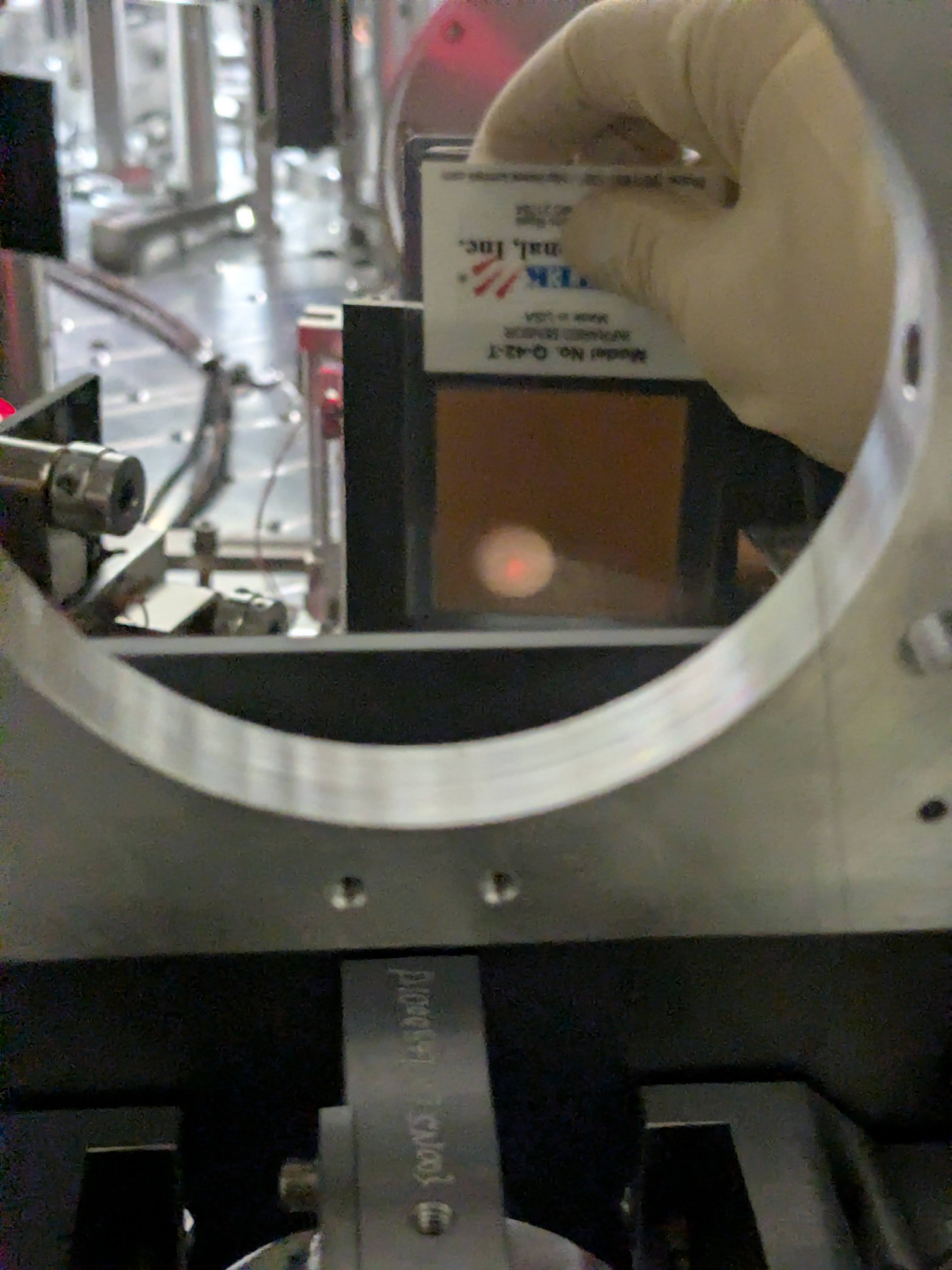
FYI, IFIinput_aftercentering.jpg shows the same baffle after we made a huge change in IM1.
We don't have any good view of that baffle so it's hard to assess, and we forgot to check it before making changes to IM123.
However, given how small the change was on IFI input baffle, we don't expect that it was very bad before. We'll have to revisit and confirm.
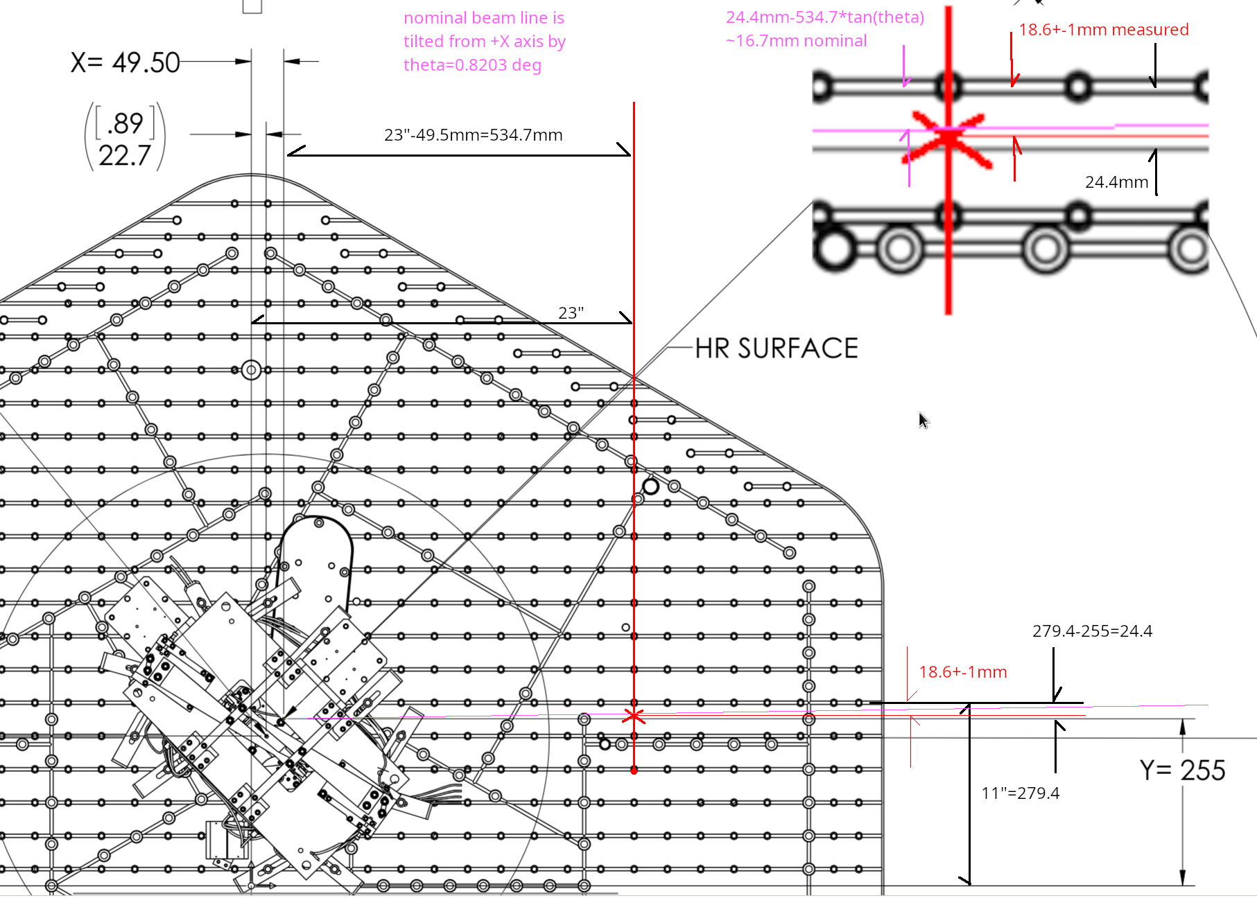
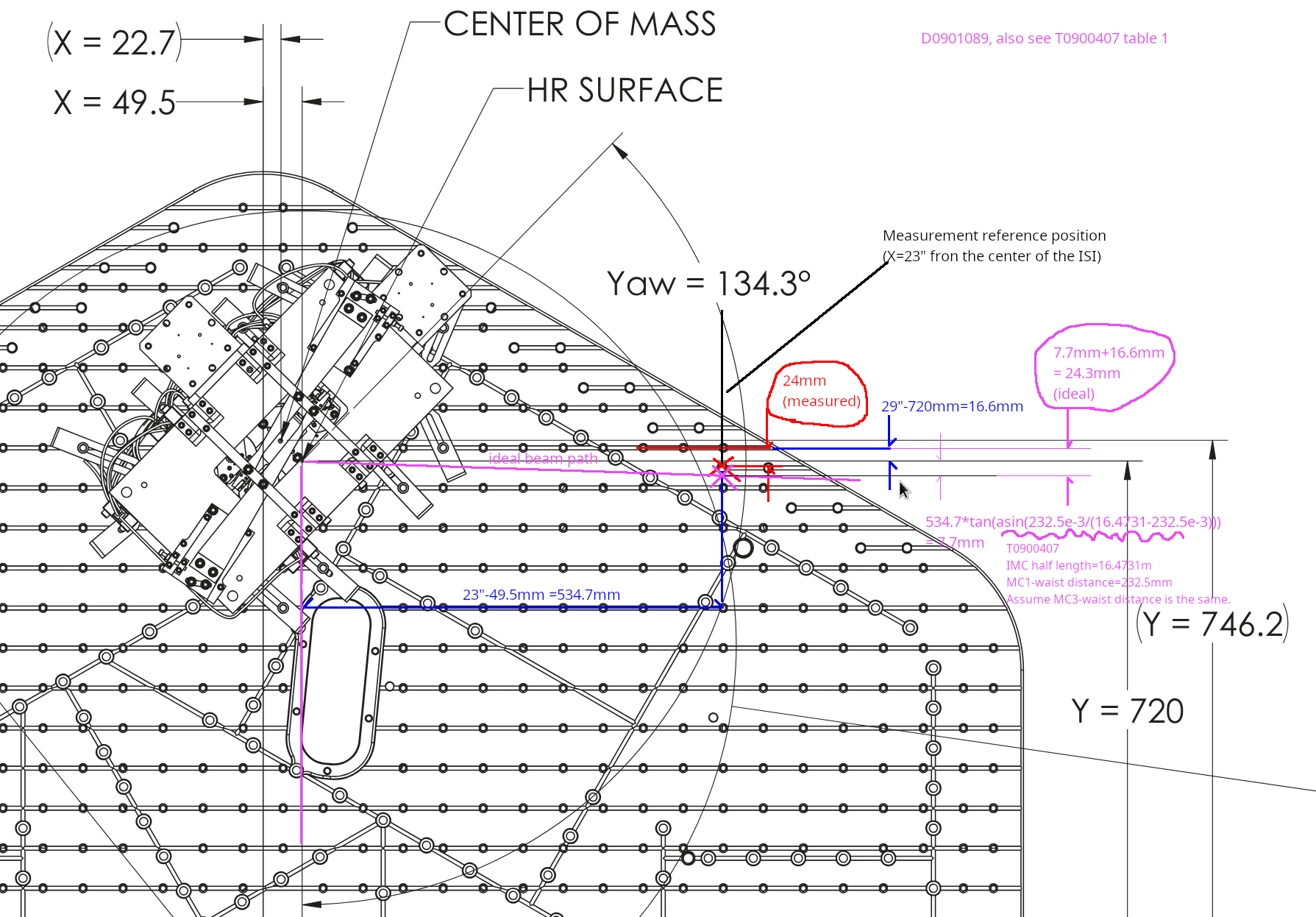
As of now, the measured beam position in front of MC mirrors are as follows this. For measurement points, see mc_beampos_measurement_cartoon.jpg. The height is pretty good for all. MC3 is great horizontally too. Beam spot on MC2 and MC1 are both shifted in -Y direction. MC2 by 3.6+-1mm, MC1 by a couple +-1mm.
| Height from ISI measured [nominal] | Horizontal shift in Y direction from the nominal beam position | |
| MC1 | 154.3 +- 1.3 [155.5] | -1.9 +- 1 |
| MC2 | 167 [166.7] | -3.6 +- 1 |
| MC3 | 154 +- 0.5 [155.5] | +0.3 +- 1 |
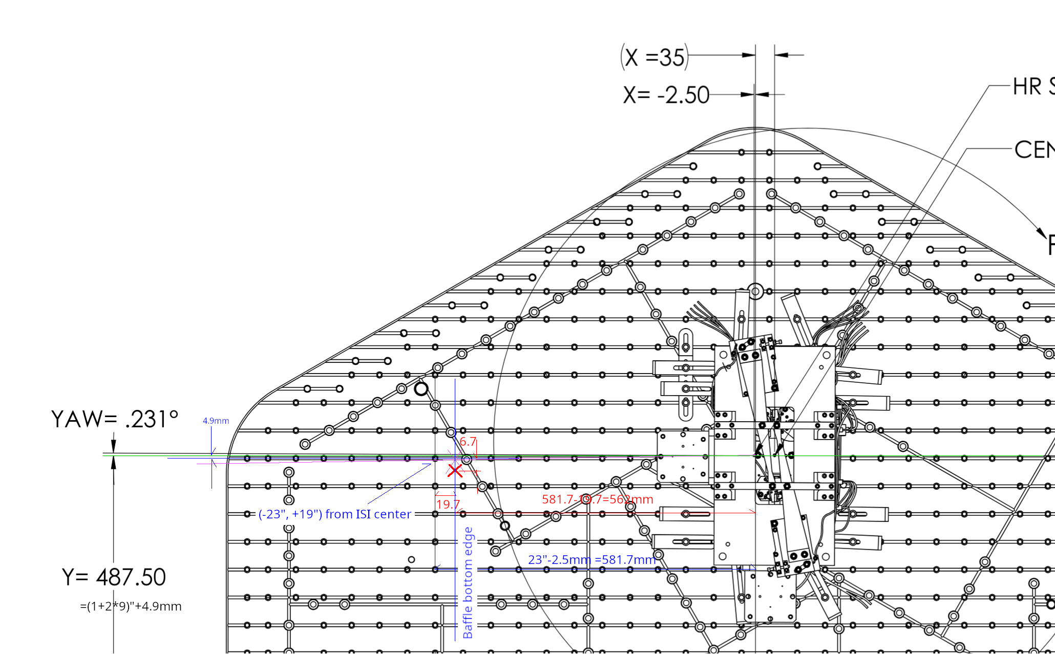
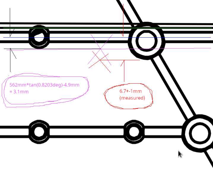
Horizontal positions were determined by covering half of the beam with a vertical hard edge (ruler etc.) and then measuring the position of the edge relative to the neighborhood screw holes using a small ruler, and then using the drawings (D0901088, D901089, D0901099) as well as other IO documents (e.g. T0900486) to figure out the nominal beam location. As an example of tedious work done, see ham2mc1.png. Due to the way it was done, we cannot determine the horizontal position of the beam much better than maybe 1/2 of the beam radius. I just put +-1mm error for all measurements. Height numbers were measured off of a ruler, the error bar (if any) is the difference between Rahul's reading and mine divided by two.
What if we move MC2 or MC3 beam spots (or both) to unclip IM4 baffle (HA12)
To get more sense of magnitude of IMC motion relative to the beam motion on IM4, I calculated how much the IMC alignment should be changed to move the beam on IM4 by 3mm in -Y direction (comfortably far from clipping but not enough to center) without moving IMs.
There are many linear combinations of the MC3 spot position and the angle of the beam coming through MC3 that will move the beam on IM4 by 3mm, so I just chose "parallel transport of MC2-MC3 line" (i.e. no angle change of the angle of the beam coming out of MC3), "rotate MC2-MC3 line around MC3" (i.e. no beam displacement on MC3) and something in-between ("rotate around MC2").
See cartoon_IMC_alignment_to_unclip.png (not to scale but the sign of displacement/rotation is correct along the entire path) and IMC_to_unclip_HA12.png (actual calculation). IMC is not the only thing that moves, we can also move IM2, but anyway. In the "parallel transport" case the beam will be move further away from the center of MC2 (remember it was already 3.6+-1mm in -Y direction to start with so the end result will be 6.8+-1mm in -Y direction). OTOH in the "rotation around MC3" case, the beam on MC2 will move by 11mm in +Y direction so the end result will be 11-3.6+-1=7.4+-1mm in +Y direction.
In all cases the beam will likely still hit the IM4_TRANS because the QPD (Excelitas C30845) has a huge 8mm active diameter, but it will likely be completely in one quadrant. So all of these will be bad solution if we believe that the IM4_TRANS position should be close enough.
Note that the "rotation around MC3" case will result in about 1mrad beam angle change on IM4. This needs to be absorbed by IM4 rotation by about 500urad to send the beam to PR2.
It's also worth noting that IM4-PRM HR distance is almost the same as IM4-IM4_TRANS distance.
What if we fix the beam on IM4_TRANS?
Instead of IMC alignment, now let's think about the beam positions from the end point (IM4_TRANS).
Again, assume that we want to keep the IM4 TRANS beam position. We tried two different IMC alignment, and the beam was clipped on IM4 baffle (HA12) after bringing the beam back to the target IM4 TRANS position.
Moving the beam position on HA12 by 3mm in -X direction without changing the IM4_TRANS position means that we shift the beam position on IM3 by about 8mm. IM3-IM4 path beam angle changes by 4.8mrad counter-clockwise. This is an absolutely huge change.
PRM should be moved by 2.4mrad, and 8mm on IM3 is already the radius of IFI output baffle (HA6) so we'll be worrying about clipping there. There seems to be no solution where the beam is far enough from the IM4 baffle (HA12) edge AND the beam is on the same position on IM4_TRANS as in vacuum.
As far as we assume that IM4_TRANS is trustworthy, it's very likely that the beam was clipping or at least very close to clipping on HA12 in O4.
However, if IM4_TRANS path moved after HAM2 was opened (i.e. somebody bumped something), IM4_TRANS position as of now doesn't mean anything. We have to at least grab and wiggle the steering mirror as well as the QPD for that path to make sure that nothing is loose. (I already did that test for MC2 TRANS, and they didn't move.)
Attached are an example of beam position measurements (in this case MC1).
IM4_TRANS path optics (pickoff for the ISS path, pico for IM4_TRANS centering) as well as the IM4_TRANS QPD itself seemed to be firmly attached to the pole and the ISI table. I grabbed them using my hand and wiggled and they didn't move at all.
The beam is level between IM1 and IM4 and then goes up toward PRM, but I cannot easily find how much. So here's a quick note.
| MC3 | IM1 | IM4 | PRM AR | PRM | |
| Height [mm] | 155.5 | 155.5- | 155.3 | 158.8 | |
| Angle [rad] of the exiting beam relative to the horizontal plane | level | 8.5m | 628u | 628u |
Nominal height of MC1 and MC3 center is 155.5mm (D09010088, D0901089). IM1 beam height should be pretty close though MC2-MC3 line is not level.
The beam from PRM HR to PRM is tilted up by 0.035966 deg = 628urad (I'm using the PIT angle of PRM itself in D0901920 rather than reading the coordinates of PRM and PR2).
PRM has 1 degree vertical wedge (D0901172), the bottom being widest, so the beam is tilted up from IM4 to PRM AR by ~(n-1)*1deg = 0.4497 deg relative to the PRM-PR2 line, n being the refractive index of fused silica for 1064nm (1.4496).
The beam from IM4 to PRM AR is therefore tilted up by (0.4497+0.035996) = 0.4857 deg = 8.5 mrad relative to the horizontal plane.
PRM center height is 158.8mm nominal (D0901090) and the distance from PRM AR to IM4 is 415.9mm (T0900486), so the beam height at IM4 should 158.8-415.9*8.5mrad = 155.3mm, which is good enough of an agreement with MC3 height.
FYI I measured the IM4 baffle height this morning and it was (206+104)/2 =155mm, so the baffle height should be correct. (The beam is low on that baffle though YAW is the worse problem than PIT.)
This is the beam position measurements for MC2 and MC3.
Note: In D0901099-V2 on page 9, it looks as if MC2 HR surface is supposed to be rotated by 0.231 degrees clockwise seen from the top.
I don't think that makes sense unless the ISI table itself is supposed to be rotated 0.231 degrees counter-clockwise because the IMC is an isosceles triangle, MC1-MC3 line is parallel to Y axis and MC2 Y coordinate is the mean of MC1 and MC3 Y coordinate according to the global coordinates of MC1, MC2 and MC3 (E1100494-V4, E1100494-V6).
I assume that the ISI tables aren't nominally rotated around local Z axis.
| Global X | Global Y | Global Z | |
| MC1 |
-20,072.0 |
255.0 |
-97.3 |
| MC2 | -3833.1 | 487.5 | -87.3 |
| MC3 |
-20,072.0 |
720.0 |
-97.3 |
TITLE: 05/21 Day Shift: 1430-2330 UTC (0730-1630 PST), all times posted in UTC
STATE of H1: Planned Engineering
INCOMING OPERATOR: None
SHIFT SUMMARY:
20:44 UTC the TSCX chiller's flow went to zero.
TJ turned the chillers back on and walked the lines to check for leaks.
Pressure and flow seems to be stable now.
VAC Alarms: Type Error while running test: VAC
GV1 is OPEN
GV5 is closed.
GV6 is closed.
Type Error cleared in VAC. I guess this is was caused by the CDS team.
DAQ restart happening at 22:28 UTC. Dave Says we are the DAQ restarts are done.
LOG:
| Start Time | System | Name | Location | Lazer_Haz | Task | Time End |
|---|---|---|---|---|---|---|
| 14:54 | VAC | Jordan | LVEA | N | Turning off the purge air. | 15:03 |
| 14:56 | VAC | Jordan & Contractor | Kobelco Pumps | N | working on VAC pumps. | 19:56 |
| 14:57 | NATR | Snake | LVEA Near PSL | N | Sneakin around looking for the mouse. | 16:27 |
| 14:58 | NATR | Mouse | LVEA Y-arm | N | Stuck in trap. | 16:27 |
| 15:16 | Safety | Richard | LVEA | N | Looking for wildlife. | 15:36 |
| 15:25 | VAC | Jordan | LVEA | N | Looking for wildlife. | 15:45 |
| 15:26 | NATR | Eric | LVEA | N | Looking for wildlife | 16:03 |
| 16:11 | EE | Fil | Mech Room | n | Working on HEPI | 18:11 |
| 16:38 | SEI | Jim, Ryan S, Shoshanna | Optics lab | N | cleaning optics | 17:36 |
| 16:42 | FAC | Kim | LVEA | N | Technical cleaning & resupply. | 17:07 |
| 16:44 | IAS | Jason | LVEA | N | Faro work on BBSS pitch and Yaw. | 19:08 |
| 17:05 | CDS | Patrick | Mech room | N | Searching for Fil | 17:14 |
| 17:08 | FAC | Randy | LVEA near BSC2 | n | taking measurements, NOT inside chamber. | 18:25 |
| 17:08 | FAC | Kim | EX | N | Technical cleaning & resupply | 19:08 |
| 17:15 | Safety | Main Gate | Main Gate | N | Main Gate is locked OPEN | 23:11 |
| 17:17 | BBSS | Betsy | LVEA | N | Driving the BBSS | 18:45 |
| 17:21 | TCS | Camilla & Madie | EY | Yes | Working with the ALS table | 18:03 |
| 17:22 | VAC | Travis | LVEA | N | Helping Besty with BBSS | 18:11 |
| 17:29 | BSC2 | TJ | LVEA BSC2 | N | Helping Randy with measurments | 17:52 |
| 18:17 | VAC | Gerardo | LVEA | N | Shutting off the Purge air valve In the LVEA | 18:45 |
| 19:06 | FAC | Randy | LVEA | N | BSC2 platform measurements. | 20:59 |
| 19:57 | BBSS | Betsy | LVEA | N | swapping osems. | 22:57 |
| 20:04 | SEI | Ryan & Shoshanna | LVEA H2 PSL | N | Building LLO CSRs | 23:03 |
| 20:15 | BBSS | Oli | LVEA | N | Helping Betsy | 00:13 |
| 20:39 | IAS | Jason | LVEA West bea | N | BBSS pitch and yaw measurements. | 23:38 |
| 20:54 | TSC | Camilla & Mitchel | Optics Lab | N | getting part? | 22:11 |
| 20:58 | CDS | Patrick | MER | N | talking with Fil | 21:02 |
| 21:03 | VAC | Fil & Jordan | MER | N | Workin on HEPI | 23:03 |
| 21:13 | TCS | TJ | LVEA | N | Checking on TCSX chiller flow rate. | 21:41 |
| 21:27 | EE | Fil | LVEA | N | Helping Betsy and Oli | 22:37 |
| 21:29 | FAC | Randy | LVEA Test stand | N | Taking more measurements. | 22:00 |
| 21:42 | SUS | Rahul | LVEA | N | Bag and Tag parts. | 22:22 |
| 22:22 | VAC | Travis | LVEA | N | Checking vac guages for glitches from the power fluxuation. | 22:26 |
| 22:40 | CDS | Dave | CUR | N | DAQ restarts to add new channels | 22:40 |
| 22:41 | CDS | Fil & Patrick | MER | N | Working on HEPI Beckhoff (Patrick \ | 00:25 |
| 22:51 | ALS | Madie Camilla | EY | YES | Measuring ALS beam | 23:51 |
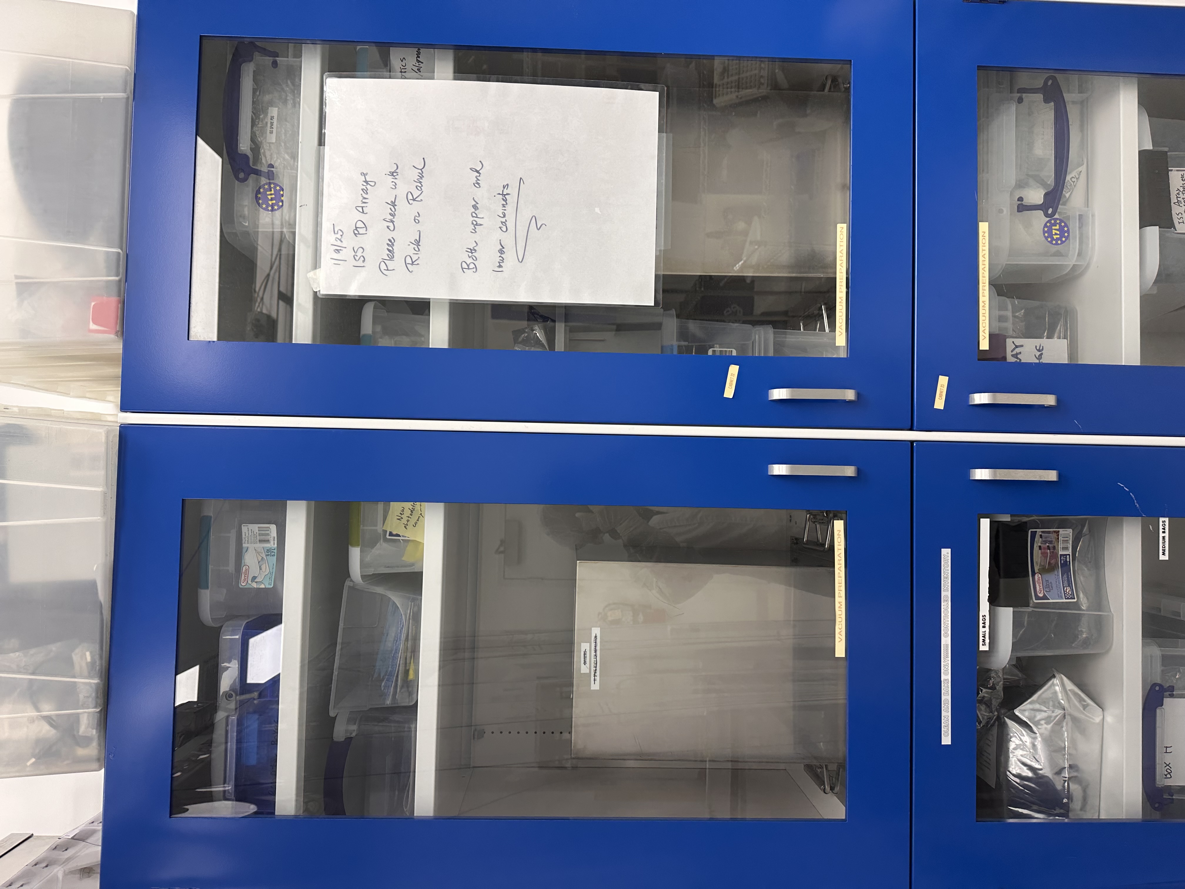
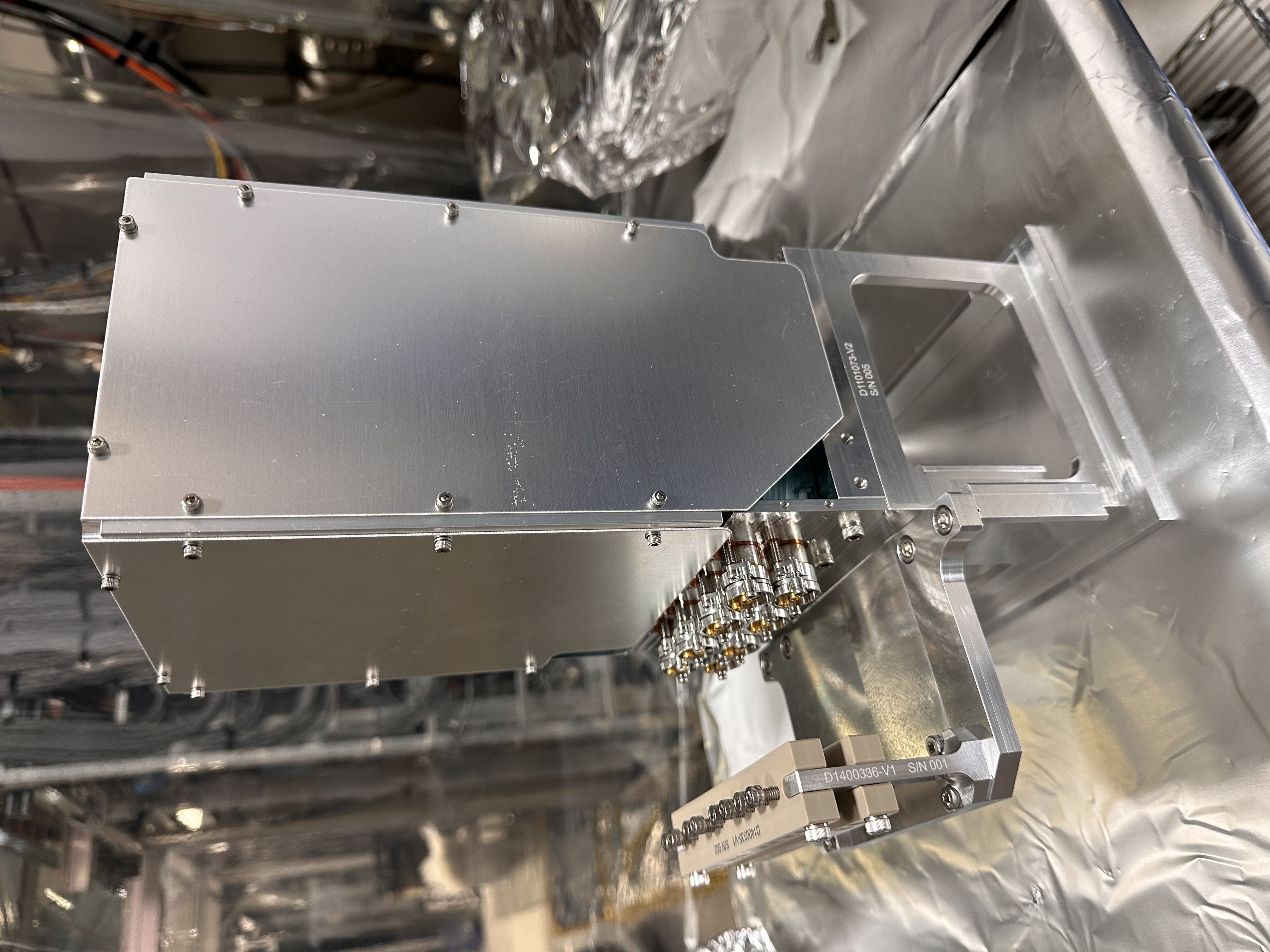
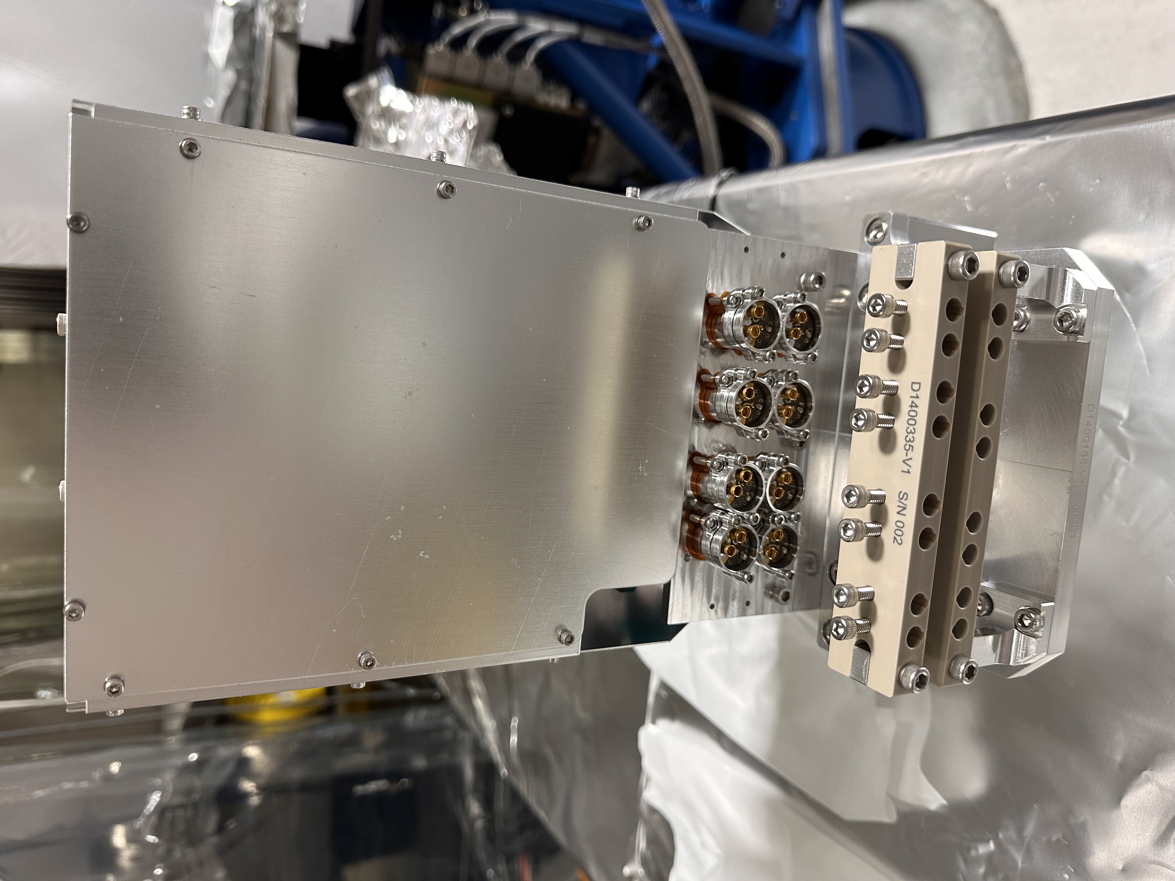
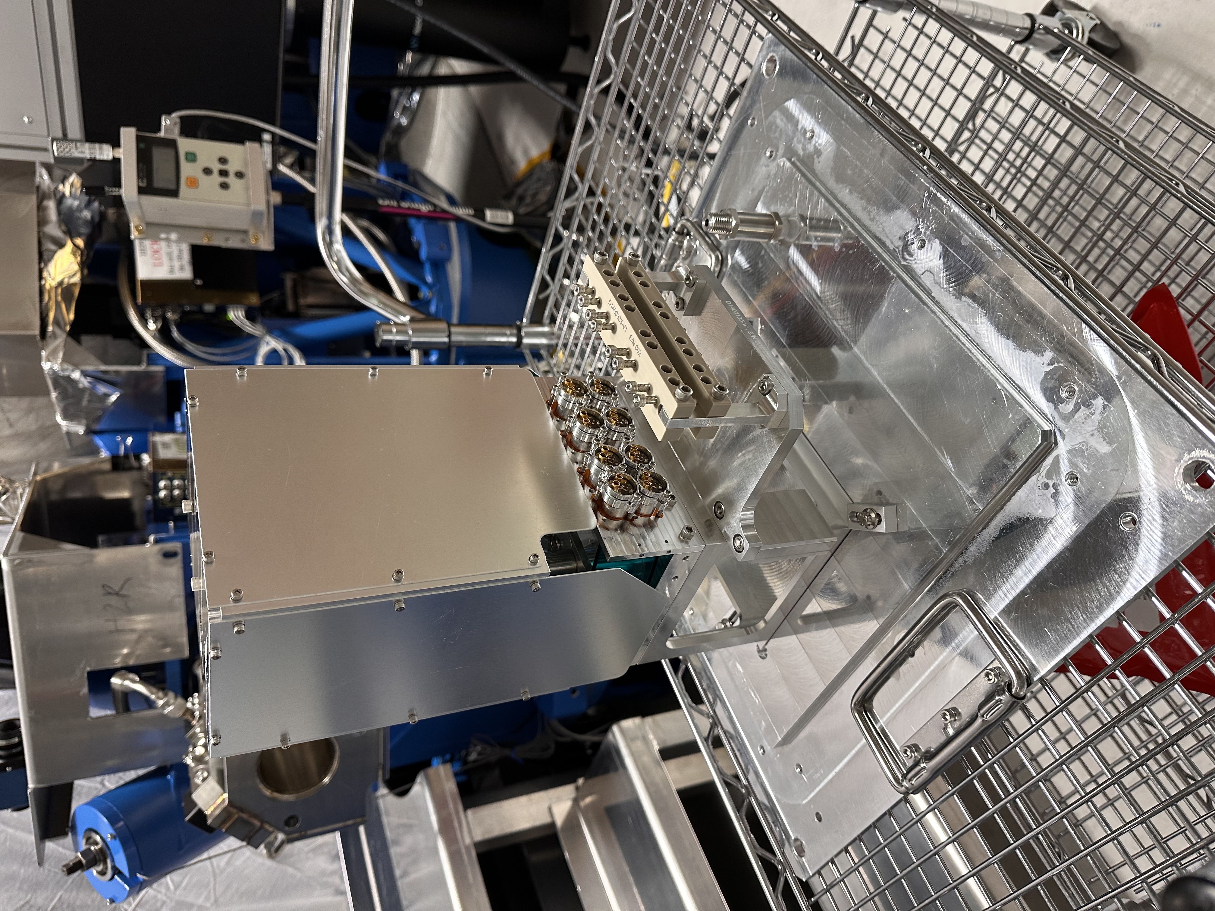
This afternoon I went into the LVEA (HAM2 clean room area) and canned & stored the old unit of the ISS PD - s/n S1202971. This unit was uninstalled on May 13th, 2026 and replaced with a new unit (S1202965) - see LHO alog 90237 for details.
I have moved this old unit (s/n S1202971) to the vacuum prep area of the optics lab (OSB) and stored it in the blue cabinet.
Please see pictures attached below for reference.
I turned the ALS Y laser back back on, ready to take some ALS beam profiles. It's been off since the interlock was worked on last month. It is now shuttered.
Ibrahim, Oli
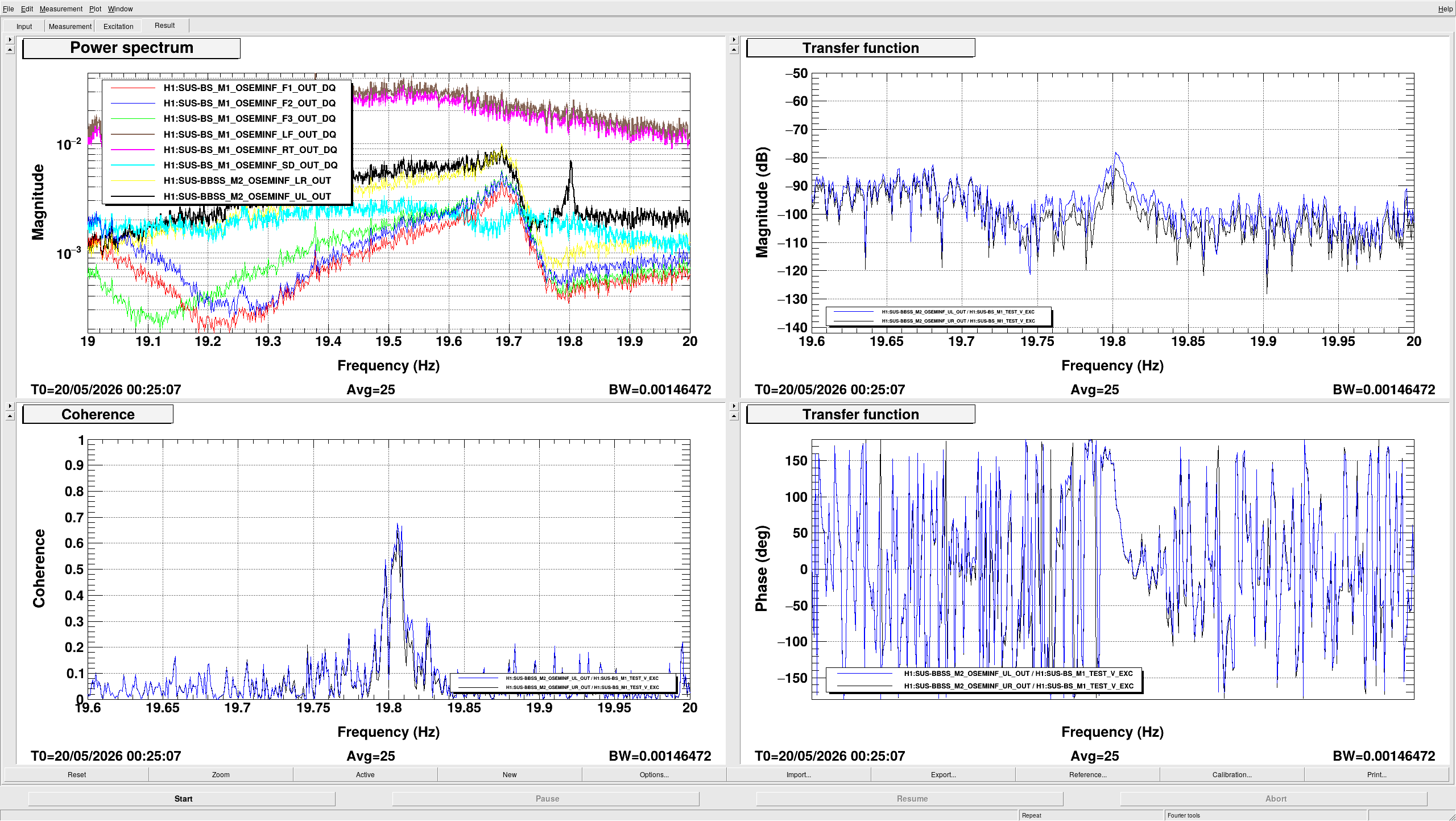
We ran a long overnight Bounce measurement on the BBSS. The BRDs weren't installed for this measurement. AOSEM flags were not installed, and we were 100g heavier at M1 than we are now (this measurements was taken before 90294).
With those settings in mind, our measurements show that our Bounce mode was at 19.80Hz. The last time these measurements were taken, back in the staging building (88141), the bounce mode with no BRDs was ~19.74Hz, so they're consistant.
The measurement file can be found in /ligo/svncommon/SusSVN/sus/trunk/BBSS/H1/BS/Common/Data/ 2026-05-19_2200_H1SUSBS_M1M2_BounceNoBRD_V_0p001to40Hz.xml as r13012.
Attached here is a zoomed in version of this file. The mode is indeed clearly visible in M2 UL, and the frequency is known well enough for proper BRD tuning. Thanks!
The Q of the mode seems to be about 3400. Maybe a higher excitation would be possible to get a better definition. Were you at the saturation limit to drive M1 V?
At 15:47 UTC the Handford site caled to tell us that they are running a drill.
The drill suggested simulating shutting off the HVAC and ventalation systems and sheltering in place.
At 16:28 UTC Hanford site called to tell us that the drill is over and we no longer need to shelter in place.
TITLE: 05/21 Day Shift: 1430-2330 UTC (0730-1630 PST), all times posted in UTC
STATE of H1: Planned Engineering
OUTGOING OPERATOR: None
CURRENT ENVIRONMENT:
SEI_ENV state: MAINTENANCE
Wind: 9mph Gusts, 5mph 3min avg
Primary useism: 0.02 μm/s
Secondary useism: 0.11 μm/s
QUICK SUMMARY:
Just a normal day where normal day things will happen.
The VAC team is turning off the Purge air, so there will not be any approval of in chamber work done today.
Jonathan, Erik, Patrick, Dave:
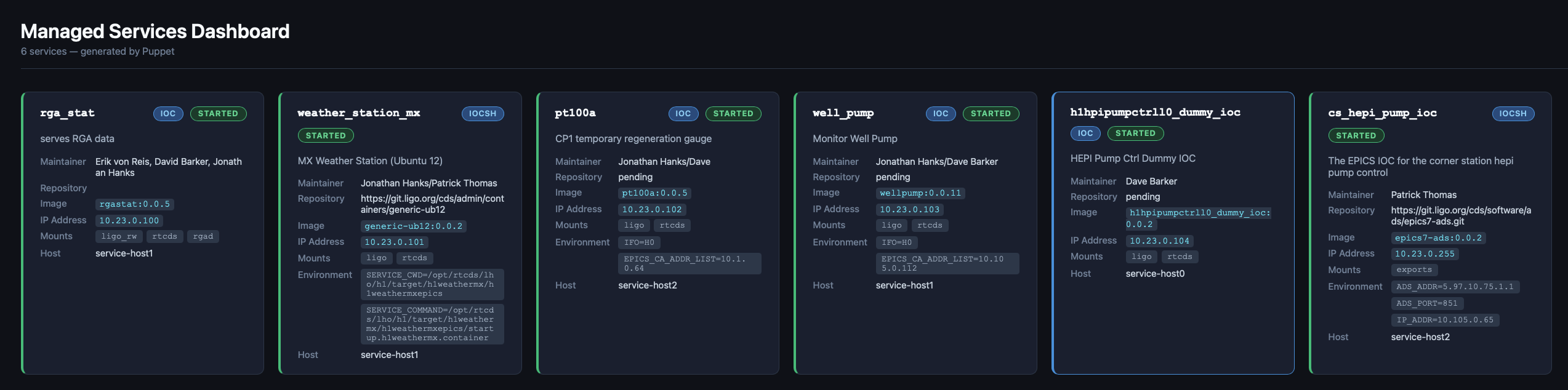
This afternoon Jonathan installed the new IOC-LAN on the service-host cluster, which increased the number of IP addresses available to containerized IOCs from a few dozen to 64k. The IOCs were restarted and assigned new addresses on this VLAN (10.23.0.0/16) [see attached dashboard]
For a brief period while the server was being updated we ran pt100a's IOC on opslogin0.
The EDC was restarted on h1susauxb13 to include 10.23.255.255 in its CA_ADDR_LIST UDP broadcast list. Similarly on cdslogin the alarms service's puppet config was updated and alarms was restarted.
TITLE: 05/20 Day Shift: 1430-2330 UTC (0730-1630 PST), all times posted in UTC
STATE of H1: Planned Engineering
INCOMING OPERATOR: None
SHIFT SUMMARY:
Lots of good work done today. Jason and crew made IAS progress over on the Beam Splitter.
Oli and Ibrahim have been working with the B-OSEMS over at the new BS too..
Vac team did some RGA baking and pump carting as per usual.
The SEI crew cleaned some CRS optics and worked on HAM3 feed throughs.
X are has been de-tumbleweeded with the big Green Machine.
LOG:
| Start Time | System | Name | Location | Lazer_Haz | Task | Time End |
|---|---|---|---|---|---|---|
| 14:30 | FAC | Randy | LVEA | n | Weighing BBSS coffin (started 14:10) | 14:31 |
| 14:57 | FAC | Kim | LVEA | n | Tech clean | 16:25 |
| 15:11 | PCAL | Tony | PCAL Lab | y(local) | Taking apeture caps off | 15:13 |
| 16:06 | IAS | Jason RyanC | LVEA West Bae | N | Big Beam Splitter work Ryan out early | 20:06 |
| 16:07 | EE | Fil | Mech Room | N | Working on HEPI system | 23:58 |
| 16:08 | FAC | Kim | LVEA | n | Technical cleaning | 16:08 |
| 16:21 | SUS | Oli & Ibrahim | LVEA West Bay | N | Aligning B-OSEMs and other SUS work | 20:22 |
| 16:23 | SPI | Jeff | Optics Lab | YES | SPI work in Laser Hazard. | 20:58 |
| 16:24 | FAC | Kim | Optics Lab | y | empting red bins. | 16:32 |
| 16:32 | VAC | Jordan | LVEA | N | Walk around the LVEA and check pumps and RGAs | 16:37 |
| 16:55 | SUS | Elenna | LVEA West | N | Giving parts to SUS folk | 17:01 |
| 17:10 | FAC | Kim | LVEA | N | Technical Cleaning. | 17:35 |
| 17:24 | FAC | Randy | X arm | N | Tumbleweeding with Big Green. | 21:06 |
| 17:41 | FAC | Kim | EY | N | Technical Cleaning | 18:51 |
| 17:52 | SEI | Travis | LVEA HAM3 | N | Working on Feedthroughs | 18:30 |
| 18:06 | SEI | Ryan S & Shoshanna | LVEA | N | Cleaning CRS optics | 19:50 |
| 18:15 | SEI | Jim | LVEA HAM3 | N | Working on feed throughs | 19:49 |
| 18:51 | SPI | Josh | LVEA HAM3 | N | SPI work near HAM3 | 20:12 |
| 20:05 | TCS | TJ & Madi | LVEA Both TCS tables | N | making sure the TCS table alignment it still good. | 20:52 |
| 20:28 | VAC | Jordan | HAM6 | N | Shutting down RGA Bake | 20:32 |
| 20:47 | SEI | Jim, Shoshanna, RyanS | Optics Lab | n | Cleaning optics | 23:47 |
| 21:01 | VAC | Travis | LVEA | n | Parts hunting | 21:29 |
| 21:01 | VAC | Jordan | Prep lab | n | Parts | 21:09 |
| 21:42 | VAC | Travis, jordan | LVEA | n | CP1 pump check | 22:02 |
| 22:08 | SUS | Oli, Madi | LVEA | n | BBS work | 00:08 |
| 22:22 | PCAL | Tony | PCAL lab | yes | Starting TSA measurement | 22:31 |
| 22:43 | VAC | Jordan | LVEA | N | Looking at scaffolding | 22:49 |
| 23:05 | VAC | Travis | LVEA | N | Checkin pump cart | 23:10 |
R. Crouch, J. Oberling, I. Abouelfettouh, O. Patane
As Ibrahim reported here, we have completed the first round of BBS position alignment (I say first round as we still have to do the pitch/yaw alignment, and that has the potential to change the position alignment so we may be doing this again). In the basis of our alignment equipment, which is set normal to the AR face of the BBS, the deviations from nominal are:
If we rotate these deviations to the XYZ axes using the BBS yaw we get deviations along those axes. I'm using the target BBS yaw for this (specifically, the AR surface yaw from the +X axis of 45.1056°), as we have yet to measure or align the actual BBS yaw, so this is more of an estimate at this point but will work for now (it takes a yaw change on the order of several degrees to change this calculation at the 0.1 mm level, so this is a pretty good estimate); this will be tightened up once we align the BBS pointing and revisit the positioning. The results (the tolerances rotate with the deviations, hence the change in X and Y):
The below table gives the target position of the center of the BBS's AR surface and the current position based on the above estimate of the XYZ deviations (all units are in mm):
| Axis | Target Position | Actual Position | Deviation | Tolerance |
| X | -160.4 | -160.5 | -0.1 | +/- 1.4 |
| Y | -226.3 | -225.8 | +0.5 | +/- 1.4 |
| Z | -83.1 | -83.2 | -0.1 | +/- 1.0 |
The next step in the alignment is to use the FARO to set up a total station/laser autocollimator combo looking along the target surface normal of the HR surface of the BBS. This will be used to align the BBS pitch and yaw. Once that is done we'll have to re-check the BBS position alignment (again, using the AR surface of the BBS) to ensure the pointing alignment did not change the optic's position (which may happen in this case as the BBS is currently, as Ibrahim reports, "quite yawed").
Ibrahim, Oli, Jason, Ryan C
Work done today:
Specifics of Optic XYZ Alignment
See pictures below.
Conclusion: T2000599-v6 (r13010) of bbssopt.m matches LHO parameters, T2000599-v5 (r12764) matches LLO's current configuration, but the difference in the models is negligible
The M3 mass listed in the bbssopt.m parameter set has been changed from 20.99kg to 20.909kg to match the mass of LHO's BBSS M3 optic.
This mass is given by the mass of the optic itself (20889g) + the mass of the primary prisms (7.56g and 7.46g) + the mass of the secondary prisms (5.57g together). This gives us 20.909kg. The change in the model from this is very minimal - the highest Pitch peak shifts down by a few hundreds of uHz, from 1.1656Hz to 1.1615Hz.
LLO's BBS02 is 21.065kg, and comparing this to the previous dummy's mass, the peaks are still in the same place, so the previous version of the model, v5 (r12764) matches with their current configuration, but since the shift is so minimal, using the same model that LHO is using would be fine.
I've updated T2000599 to -v6, and committed /ligo/svncommon/SusSVN/sus/trunk/Common/MatlabTools/TripleModel_Production/bbssopt.m to r13010.
The comparison for all DOFs for all three mass changes can be found at /ligo/svncommon/SusSVN/sus/trunk/BBSS/Common/Results/comparetripleparams/2026-05-20_M3_DummyvsLHOvsLLO/triplemodelcomp_2026-05-20_M3_DummyvsLHOvsLLO_M1toM1.pdf and committed to svn as r13011.
TITLE: 05/20 Day Shift: 1430-2330 UTC (0730-1630 PST), all times posted in UTC
STATE of H1: Planned Engineering
OUTGOING OPERATOR: None
CURRENT ENVIRONMENT:
SEI_ENV state: MAINTENANCE
Wind: 2mph Gusts, 0mph 3min avg
Primary useism: 0.01 μm/s
Secondary useism: 0.16 μm/s
QUICK SUMMARY:
We are currently in LASER SAFE for some BBSS and tomorrow's VAC work, but might go back to HAZARD in the afternoon for more HAM2 work.
Here's a look at some old data from september's OM2 heating test. I'm posting this incomplete alog, which has been sitting in my drafts for a long time, so that at least this information is available to people.
Background about the measurements:
Information about this dataset, bold numbers are used as assumptions in these models:
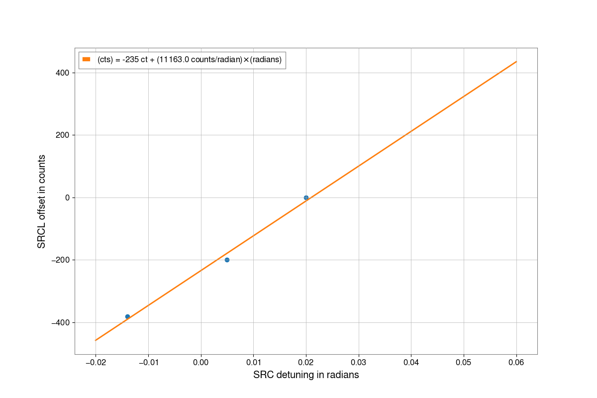
Here is a plot with all of this data, we took mean sqz data for all three data sets with the LO unlocked, we only took anti-squeezing data for the first OM2 hot data set without adjusting the SRCL offset. The low frequency non quantum noise is worse for the OM2 hot data because we didn't retune the feedforwards after heating up.
Some gwinc plots to help me understand the impact of mismatch phase:
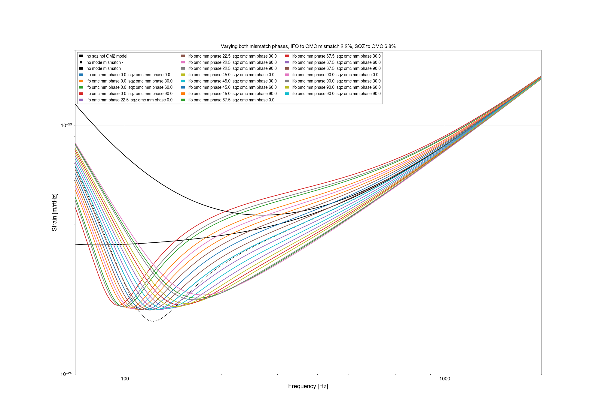
In gwinc the mismatch is parameterized as IFO to OMC, and SQZ to OMC, since we have not adjusted the psams while we heated up OM2 we will need to increase both of these mismatches for the hot OM2 state, and both of them have a mistmatch phase which changes the frequency dependent rotation significantly. This rotation is most obvious for the mid- squeezing traces, where we adjusted the squeezing angle so that the high frequency noise matches what it is when there is no squeezing. To help myself understand, I made some plots that show a series of models with our measured mismatch magnitudes listed above and the squeezing angle fit for high frequency, varying ifo to omc mismatch phases, or sqz to OMC mismatch phases. Here is another plot showing only one type of mid sqz with both phases varying, which may also be helpful to look at to see the envelope of what varying the mismatch phase can do. Kevin has said that the only thing that matters is the relative mismatch phase, this plot illustrates that where most of the traces can't be seen because they are hidden by others with the same relative mismatch phase. The traces where two mismatch phases are identical are closest to the trace with no mismatch.
Looking at losses:
Looking at the plot with all the data, you can see that the mean squeezing is mostly the same for the three cases, above 200 Hz, suggesting that the losses are about the same for all three cases. Below 200 Hz, there is as usual some kind of extra noise that makes the mean sqz trace not useful for estimating loss. We only measured anti-squeezing for the hot OM2 case before we added the SRCL offset. This plot of a model of anti-squeezing shows that we don't expect much difference in anti-squeezing for the level of mode mismatch and SRCL offset that we have, except around 20Hz where technical noise would cover the quantum noise.
There are two ways to use these data to estimate unknown losses. I've used 2-2.3kHz since the technical noise is further from the shot noise than in other parts of the spectrum. Assuming an arm power of 330kW we can use no sqz data to estimate readout losses, doing that we need to add just a small amount of extra losses to explain our shot noise: 1.5% for cold OM2, 2.4% for hot OM2 no change in SRCL offset, 0.9% for hot OM2 with SRCL offset changed. This is encouraging since it means that we can account for most of our readout losses, however it doesn't agree with the estimate based on kappa C for the change in losses as OM2 was heated. We can also use the nonlinear gain and unlocked squeezing level to estimate unknown loss: cold OM2: 15.1%, hot OM2: 15.7%, hot OM2 SRCL offset: 19.8%.
J. Kissel Picking up from yesterday's work (2026-05-18, LHO:90270), today I: - Verified Bram's idea on how to resolve yesterday's UNSOLVED SIDEQUEST (1) regarding ~120 Hz noise seen on FBR_PWRIN_REF PD (LHO:90279) -- it's just the room lights. Check out this pic of o-scope timeseries of that PD readout with no lights, room lights, then clean room lights on. *sigh* Alright. RESOLVED: no big deal; when I want to use that PD, turn off the lights. - Resumed migration of optics: . Finish up REF beam path by migrating and installing M_B3 to steer REF beam into IFO_MEAS_A. Confirmed that Reflective surface is within the mount, and protruding AR surface faces M_M2 and IFO_MEAS_B. . Nothing to align here, it's a fixed optic, but checked alignment of REF beam into both IFO_MEAS_A and IFO_MEAS_B with irises in D2400143 breadboard holes 85 and 82. . Migrated D_IFO_MEAS_A and D_IFO_MEAS_B and aligned PD reflection into them with slop of PD housing moutning holes :: For D_IFO_MEAS_A Changed out smaller 1.0"x075" D1800140 Type 07 plate for bigger 1.16" x 1.16" D2000228-v1 DLC coated plate that we'd found to rectify the (lesser) stray beam from FBR_PWRIN_REF during D2400107-v4 build. As discussed, in the D2400107-v5 build, we're gunna need a whole different solution (LHO:90277). . Migrated and aligned M_B1 using holes 103 and 94. . Migrated M_M1, but needed to swap left-handed mount with right-handed mount due to interference of pico motor body with alignment pegs. More on this in the comments. . Aligned M_M1 using holes 92 and 87 (M_M4 and M_M5 are NOT installed) . Secured alignment adjustment screw set screws for M_F1 and M_B1 since these shall never be touched again. Tweaked M_M1 alignment to follow minor beam change when securing those screws. . Migrated and aligned M_M4 using holes 81 and 79 . Migrated and aligned M_M2, and . et voila! A little tweak of M_M2 and I had a heterodyne beat note to use for finishing alignment. Attached are End-of-day board status, and the MEAS IFO heterodyne victory lap. Crude estimate of the efficiency (without accounting for dark offsets): Max = 6.60 V Min = 1.08 V Amp = 5.52 V Mean = 3.85 V efficiency = Amp / (2*Mean) MEAS A 5.52 / (2*3.85) = 0.717 = ~72% MEAS B 5.52 / (2*3.82) = 0.723 = ~72% Excellent. Tomorrow we install the last two optics and align the REF IFO, and we're back in business! Estimated readiness for install May 26 2026!
As per WP 13257 we configured the network to create a dedicated subnet for IOCs and other services. This is in support of our work to improve our infrastructure and management of IOCs and services in CDS. This included network switch reconfiguration and extending the CDS environment. The edc will need a restart to be able to see the new subnet. This will be held off until we actually put something in the network that it needs to record.
Starting with yesterday's alignment, we tried to move the beam spots on IFI input baffle (using IM1), IFI output baffle (using IM2) and the baffle in front of IM4 (using IM3).
We had to make a huge change in all of the optics used: IM1 yaw: -500 urad, IM2 yaw: -900 urad, IM3 yaw: -720 urad.
Forgot to measure PIT/YAW position of IM4_TRANS (and we cannot trend it as we need fast data of segments) but the beam was on IM4_TRANS with almost full IM4_TRANS_SUM.
IMs didn't rail but this is clearly NOT the right way to move. Instead, what we need seems to be to shift the beam position on MC3 by a few mm in -X-Y direction.
We didn't bother to move PRM nor IM4 so the IFO REFL was again misaligned badly.
(One thing to note is that with this drastic change in the input alignment, the beam was still hitting the IM4 TRANS but not ISS QPD. However, just by turning IM3 we were able to regain the beam on ISS QPD. Now I'm fully confident that, whatever alignment we end up having after pumping down, as far as the beam is on IM4 TRANS, we can find the beam on ISS QPD by scanning IM3 (and IM2 if necessary) and slowly walk the beam using the picos to have a good alignment in the ISS path.)
We also measured the beam position (both height and Y position relative to the ideal beam path measured at specific X coordinate) to better understand the IMC beam. Numbers are to follow, but the gist is that the beam position is good (i.e. likely centered) on MC3 but is off in -Y direction by 3mm or so on MC2 even though MC TRANS is close to center.
So, for tomorrow:
My guess is that the beam has been (at least very close to) clipped by some of the IO baffles for a long time, and the above practice is to see if there is an alignment where the beam is at least not clipped.
Just want to add here that I undid all slider changes we made on Tuesday, specifically these: "IM1 yaw: -500 urad, IM2 yaw: -900 urad, IM3 yaw: -720 urad"
While these changes did not saturate the suspensions, IM2 and IM3 were very close to saturation, and we would not want to operate with them at those positions.
[Keita, Rahul, Elenna]
Today I moved IM2 and IM3 to bring the beam back to our reference position on IM4 trans QPD and center it on ISS QPD after Keita's move of the mode cleaner mirrors in 90259. This requires some iteration back and forth on both suspensions.
Our desired positon on IM4 trans is P = 0.22 and Y = -0.06. On ISS QPD, it is centered, so P=0 and Y=0.
We are driving MC2 in length, so the mode cleaner is flashing, and there are bright flashes on the QPDs. I am pausing ndscope on a flash and measuring the height of the peak in the fast channel and calculating the pit and yaw position from each QDP segment.
| Start | End | ||
| IM2 P slider | 765 | IM2 P slider | 810 |
| IM2 Y slider | -187.7 | IM2 Y slider | -88.7 |
| IM3 P slider | -560.7 | IM3 P slider | -614.7 |
| IM3 Y slider | 320 | IM3 Y slider | 385 |
| IM4 trans PIT | 0.390 | IM4 trans P | 0.268 |
| IM4 trans YAW | 0.450 | IM4 trans Y | 0.010 |
| ISS QPD PIT | -0.379 | ISS QPD PIT | -0.059 |
| ISS QPD YAW | -0.455 | ISS QPD YAW | 0.08 |
Unfortunately, this still results in clipping on the baffles Keita notes above, so we will keep going.
At the nominal IM4 trans position, yaw is pretty well centered. I then moved IM2 to both edges of IM4 trans QPD.
I changed the IM2 yaw slider to -250.7, which brought the yaw position on IM4 trans to 0.85. This made the clipping worse.
I changed the IM2 yaw slider to 90.3, which brought the yaw position on IM4 trans to -0.88. This was still not good enough to fix the clipping on the baffle.
By making a very large move to IM2 yaw slider value of 710.3, this centered the beam in the IM4 baffle. This is a ~800 urad move according to the osems and slider. The IFO REFL beam is still clipped.
I undid the 800 urad move, so the IM2 yaw slider is back to -88.7 for now.
Keita and Rahul went out to measure the position of the beam on MCs 1,2 and 3. We think that we need to make a move of these three mirrors to see if we can unclip the beam on these baffles that way.
We want to note that the positive yaw move of IM2 corresponds to unclipping on the IM4 baffle, this is consistent with the beam motion observed in chamber in the -X direction. However, this is contradictory to the sign on IM4 trans QPD, which was moving to negative yaw when we did this move. We suspect that the segment defintion must be wrong somewhere.
Keita will say more later once we have a chance to analyze the positions in chamber.
To clarify, the slider values of IM2 and IM3 are left at the "end" positions on the table above.
I trended the power measured at IM4 trans compared to the IMC input power for the entirety of the run. Some notes:
Because of this recalibration, I decided to compare both the IM4_TRANS_INMON and IM4_TRANS_OUT16 to IMC-PWR_IN_OUT16
FM10 in the IM4 trans filter bank is a factor that Craig and Georgia determined in the alog linked above, 4.606. I trended the inmon channel and multipled it by this number, ignoring other calibration factors present in the filter bank.
Therefore, the plotted ratio of IM4_trans [IN, OUT] / IMC power IN will help us understand how the power at IM4 trans changed throughout the run, like perhaps if the amount of clipping on the way to IM4 has changed.
I am comparing the ratios of both IM4 trans IN and OUT just in case we get confused by the changing calibration of the diode. I took an hourly median of these channels so we are not confused by random variation and masked the times to only show when IMC lock was either in state 100 (locked) or 70 (ISS ON).
Overall, the amount of power arriving on IM4 trans has definitely changed throughout the run.
Notably, during the vent between O4a and O4b, the amount of power measured at IM4 trans dropped. We chose not to move the IMs, and instead Sheila picoed to recenter on IM4 trans, linked above. Another power drop occured again during O4b. This time, we moved IMs to fix it. At the start of O4c is when Sheila and I recalibrated the diode, hence the disagreement with IN and OUT channels.
The second plot attached shows how the pitch and yaw on IM4 trans has varied alongside the power.
Based on what Keita can see happening in the chamber with baffle clipping, it is possible that during these alignment shifts, the amount of clipping in HAM2 on the IO baffles was changing, so the amount of power making it to IM4 trans and the amount of power going into the IFO was changing.
Specifically, I want to emphasize that with Craig's integrating sphere measurements in HAM1, we assumed that all loss between HAM1 and the PRM in HAM2 was known, i.e. loss from the IFI, etc. However, if there was additional loss on that path that changed with input alignment shifts, that would explain the apparent IM4 trans power changes during O4. Notably, Sheila and I recalibrated IM4 trans in O4c because after we fixed the input alignment in late O4b, we got more power on IM4 trans than we had gotten all run (see the jump around day 600 on the attached plots). I thought this was not physically possible, so we adjusted the calibration. Perhaps instead, we changed the amount of clipping in HAM2, giving us more light on the PRM than we had seen all of O4.
This may also help explain some of our arm power measurement mysteries if we actually had less input power than assumed.
I just want to add a clarification that we have been trying to replicate the alignment onto IM4 trans QPD, so we are trying to align to the previous pitch and yaw position. However, for O4, the beam was nearly falling off the ISS QPD, so we don't want to replicate that alignment (the pitch and yaw values on ISS QPD were like +- 0.9). We have decided to go with centering the beam on ISS QPD, especially since we have adjusted the ISS pico mirrors to find that alignment.
Yeah this yaw adjustment was no fun. Here at Livingston, it took us a decent part of a day but we think we got a good system going by the end.
We adjusted only one side at a time. We tried to keep the way we unlocked/torqued the 5 bolts of the top blade assembly consistent (see photo attached). When we unlocked we tried to only get the bolts barely loose and back them out as little as possible. Each time we locked the 5 bolts down, we found that the structure moved around 0-4 minutes in a consistent direction. By following the attached photo procedure, the yaw seemed to settle consistently 2ish arcminutes off of its unlocked value in the same direction each time. For example, unlocked we would set the BBSS at 45 degrees - 5 arcminutes, and when we locked it down we would get 45 degrees - 3 arcminutes. We repeated the process until we got lucky and the suspension locked in the right place. This took a lot of trial and error. There is some hysteresis in the push/pull screw adjustment. The yaw adjustment is not very good or repeatable.
To make matters worse, the LF and RT OSEM plates have the circular inset that houses the disk that the magnet flag of M1 sits on. This is a place where it is very easy to get subtle rubbing and it is hard to verify by eye. We did this alignment with the QOSEMs which was somewhat of a blessing because the Y direction readback of the QOSEM can act as a guide to tell you if you should start to be concerned about rubbing. It might be worth removing the LF and RT OSEM plates and see if you can to the alignment without roll or vertical damping to avoid this rubbing. If the suspension is moving too much to not have V and R damping, you must frequently adjust the LF and RT OSEMS to ensure that there is no rubbing at that location.