david.barker@LIGO.ORG - posted 15:29, Thursday 16 July 2026 (91080)
15:23 power glitch
lights flickered 15:23:39
Images attached to this report
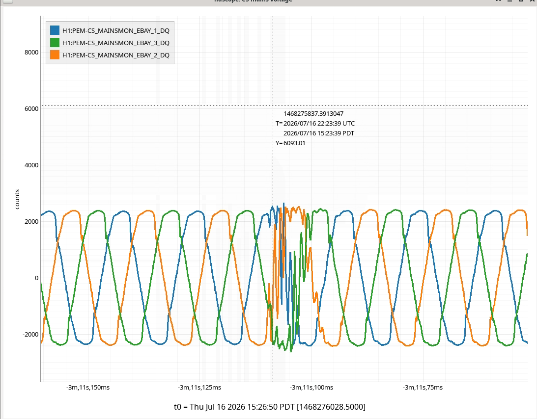
lights flickered 15:23:39
Alignment into JAC was not great. Since JAC wasn't thermalized yet (heater was turned on merely 30minutes or so before we started aligning) and the fringes weren't staying put relative to the PZT voltage, I injected more than 250Vpp (with an appropriate offset) into JAC PZT to make sure that more than FSR is scanned and manually aligned JM1 and PSL PZT until 10/01 mode became less than 10% of 00 mode. Didn't bother to refine further. Attached shows the JM1 and PSL PZT alignment offsets.
I zero-ed the dark offset of JAC_REFL_A_RF43.
We had to turn on FM10 ("W_in_HAM2" which is not calibrated in reality) which was disabled at some point.
JAC guardian was able to lock JAC after the above.
We are able to see flashing in MC TRANS camera now, seems like it's mainly off in yaw but we can see 00 mode once in a while. Nothing in MC REFL camera, we'll work on IOT2L next.

IOT2L alignment 1st round (Jennie, Elenna, Keita)
Without doing any fine alignment, IMC REFL diode was centered using the steering mirror after the bottom periscope mirror. Shifted one of the beam dumps a bit as I felt like one of the beam dumps for blocking the wrong polarization beams (or maybe AR reflections) was too close to the main beam.
IMC WFS sensors were centered using pico mirrors.
IMC REFL camera was centered using the last steering mirror.
After this, we found that JM3 needed to be rotated in PIT (which means YAW in the IMC coordinate) to roughly align the JAC output into IMC.
| before I started | after roughly aligned | |
| H1:SUS-JM3_M1_OPTICALIGN_P_OFFSET | -54 | 85 |
| H1:SUS-JM3_M1_OPTICALIGN_Y_OFFSET | 297 | 297 |
Attached video shows how the MC REFL beam goes dark when IMC is locked for a few seconds. As you can see the alignment is already pretty reasonable. This is just manual lock via fast path, no boost no feedback to MC2 no nothing. IMC guardian doesn't want to lock IMC (yet).
I disabled all ASC output to mirrors and set the H1:IMC-WFS_GAIN to zero so LOCK state should not confuse you about the alignment even if ASC is "turned on".
Jennie and I continued trying to lock the IMC for a bit this evening after Keita's attempts, but weren't successful.
We did discover, however, that an MC2 length excitation was left running, which may have confused some of the locking attempts when using the Guardian. We killed this excitation and tried the Guardian again, but still no luck. Jennie also discovered when browsing SDFs that the IMC-L gain had been stepped from 1.0 to 0.1 then 0.01 at around 00:30 UTC. We assumed this was part of Keita's locking attempts, but since it was not mentioned as necessary in any logs and it had been 1.0 for several years, we put the gain back to 1.0 and tried the Guardian once more. Sadly, this didn't seem to help either. We're leaving the IMC-L gain here and if someone else deems it should be different, they're welcome to change it back.
MCL gain was me (sorry).
Excitation was me, too (sorry again) but it was 1 ct pk-pk and has zero effect on locking.
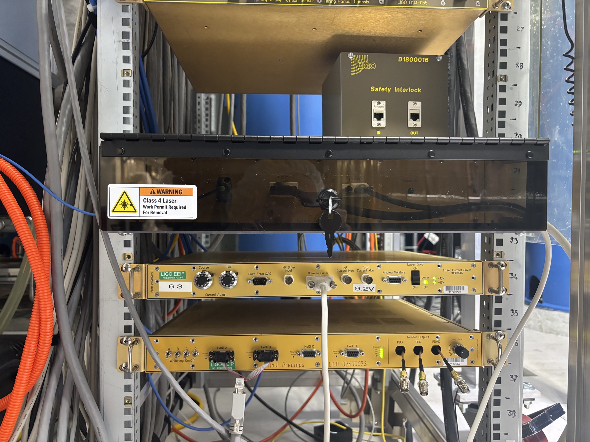
I finished hooking up everything to the new CRS laser chassis (see alog 91067 and photo attached) and turned on the laser. There will be a couple of changes to be made to the chassis (swtiching which chassis the the plexi box covers, attaching stickers etc.) but for now the CRS is up and running (minus damping). I'll continue to keep an eye on it, but until the damping is hooked up it seems unlikely that it will damp down on it's own while there's still activity in the LVEA
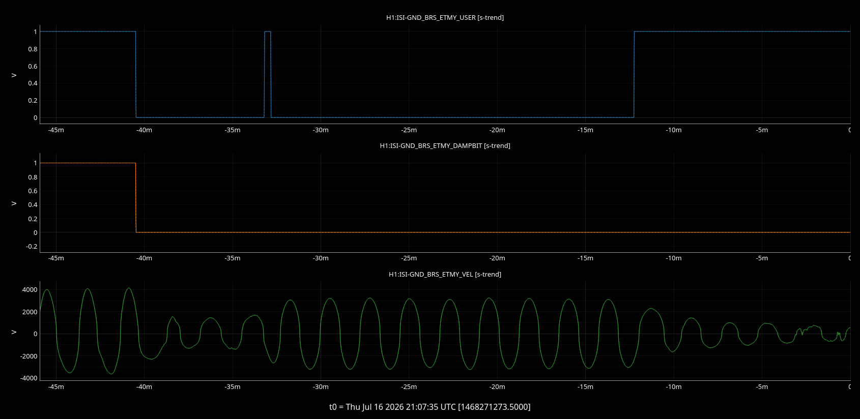
After the power outage last night the ETMY BRSs thresholds were changed and the BRS was stuck in a damping loop again.
I've changed the H1:ISI-GND_BRS_ETMY_HIGHTHRESHOLD from 8000-->4000 and did the usual 'disable the damping from 20 minutes and then re-enable it'
This might just be me not fully understanding the damping controls, but confusingly, when I re-enabled the damping, the BRS began to damp down despite the BRS remaining in the "BRS GOOD" state and the damping remaining off (shown in picture below, USER channel is whether damping is enabled or disabled, DAMPBIT is whether the damping is on or off.
This could be me not fully understanding the system, but it might explain why BRSY has had so many issues
At 20:40 UTC I turned off all the in-chamber illuminators that had been on for vent work (HAM3 and BSC1-3).
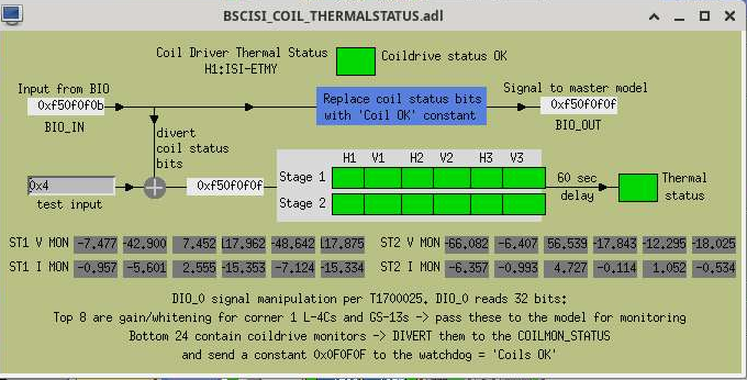
I haven't found the alog, but there is a known issue with the ETMY ISI coilmon readbacks where they report the ISI coil drivers are tripped, but are in fact not. This seems to clear up after the coil drivers warm up over a few hours. This can be fixed by putting a test offset in the test input field on the BSCISI_COIL_THERMALSTATUS screen ( opened Overtemp link on the lower right of the BSC ISI overview screen). So far I have had to put 0xc, then 0x4 to clear up the coil driver status bitword, as show in the attached screen shot. Probably something wrong with something in one of the coildrivers.
The lights on the front of the coil driver don't seem affected by this, so if the overtemp protection is clear on the chassis in the rack, you need to do a bit of hexadecimal math to do clear the coilmon warning. To clear the current issue with the coilmon bit you need to find the difference between the good bitword (0xf50f0f0f) value and the current (0xf50f0f0b in the screenshot), so 0xf50f0f0f-0xf50f0f0b=0x4 is the value that goes into the test input field. This should go back to 0x0 after what ever component in the rack stops being grumpy.
We have mostly recovered SEI and SUS, SUS pointing is still being verified and the BRSes are having issues. HV still needs to be enabled for further recovery. Team CDS is still working on some issues, IPC errors, long range dolphin, timing error at the CS...
WP 13426
The CRS laser Chassis D2600190 was installed in rack TCS-R2. Chassis houses the CRS laser, mount, and fiber spool. A plexi security cover was installed over the chassis.
The plexi should be installed in front of the Laser Driver D1500207 rather than in front of the D2600190 chassis.
J. Oberling, R. Short, P. Thomas
We have recovered the PSL after this morning's power outage. Once again, the PSL software did not autostart so Patrick was called in to get things up and running. The system calibrations were all correct this time EXCEPT for the operating hours; we trended these to the time of the power outage and updated them manually (the OPHRS A, or the total system uptime, are still incorrect as this field is not updateable and we lost it over multiple failures of the system to retain the calibration settings). I've attached a picture of the current settings screen.
The PMC relocked without issue, although it is running a little cooler than usual ( ~304.5 K vs ~306.0 K). We'll monitor this as the system thermalizes and change the PMC temperature if necessary. The FSS RefCav also locked without issue. We have left the ISS off while the system thermalizes, please do not turn it on until things have settled down (hopefully by the end of the day).

refcav temperature seems to be good as of now. I readjusted the fiber polarization controller and ALSX PLL relocked right away. ALSY PLL relocked after TJ restarted the laser.
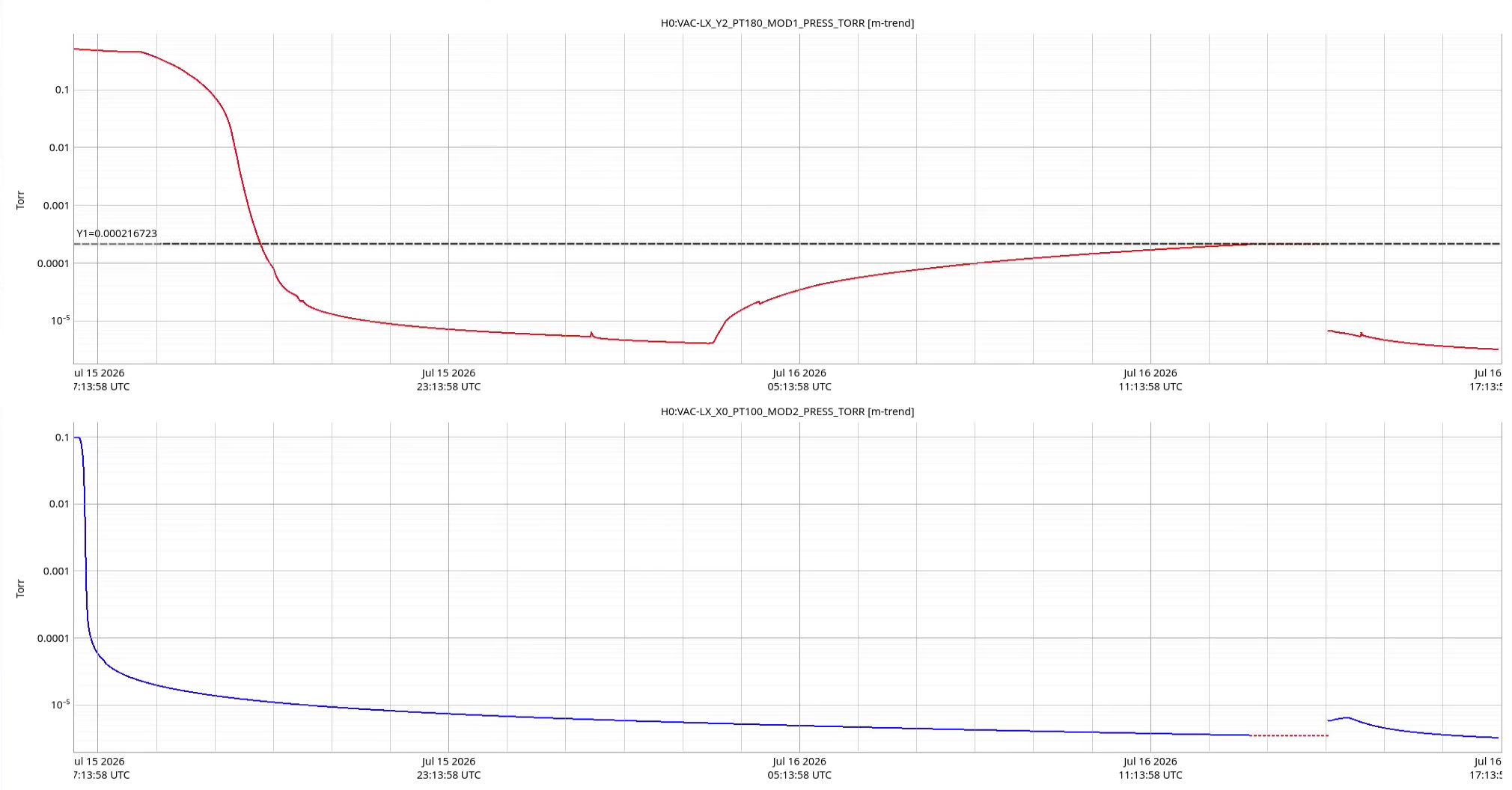
Power storm last night tripped all 3 turbos and a couple of aux carts. Pressure rose up to about 2.1x10-04 Torr, noted on the attached plot.
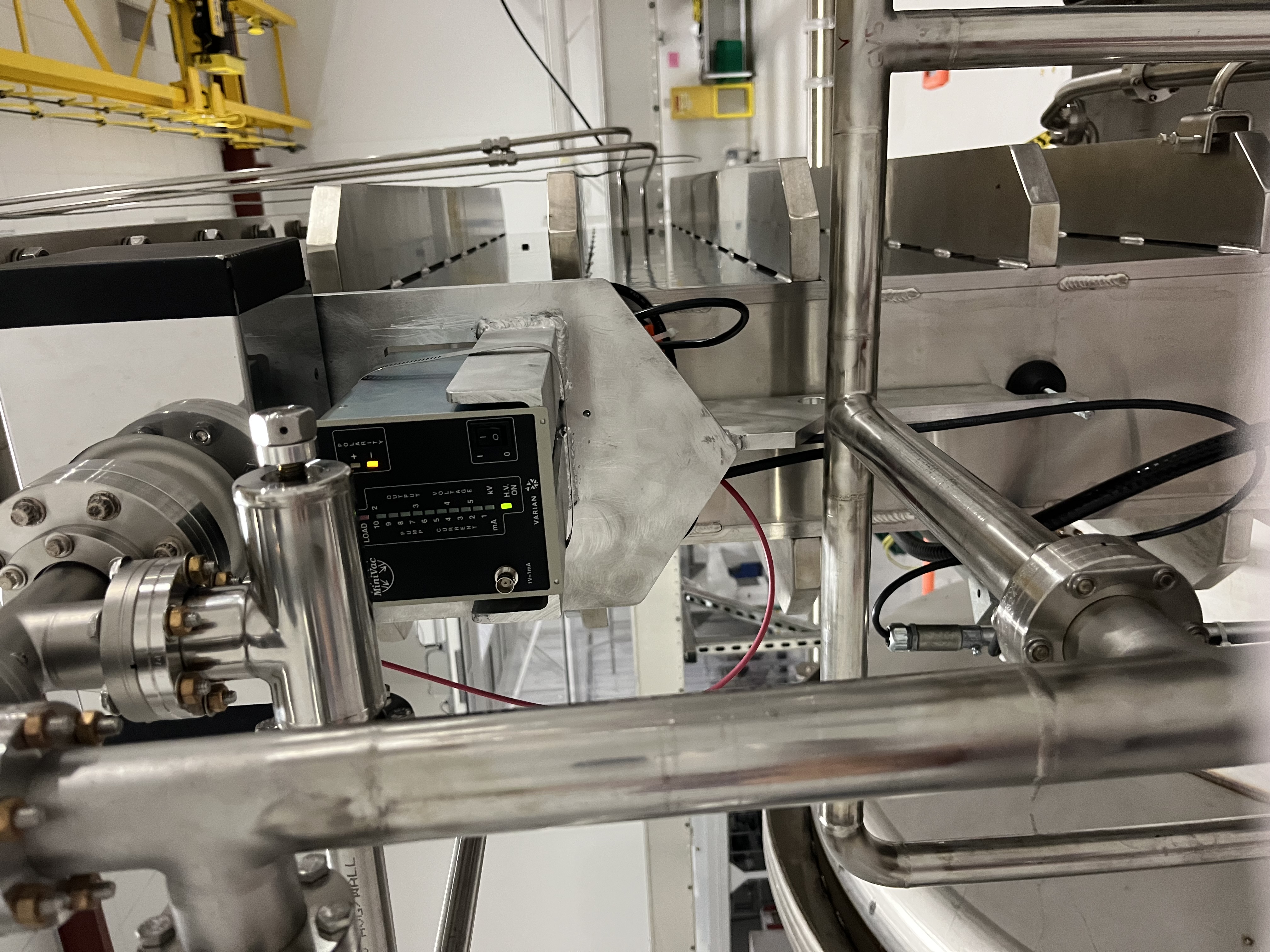
As I was doing recovery work on the output mode cleaner tube turbo pump, I had just closed the main isolation valve and "reset" the box, I was taking a photo of the as found when we had the 6:01 am power glitch.
I returned to HAM1 SS-500 to check the system, it tripped, and I recovered pumping on the SS-500 system and HAM1 turbo. Moved back to the OMT turbo pumps system, by now the main isolation valve was closed, restarted the different components and spun up the turbo pump, while this one reached "normal" speed I moved to the other two turbo stations, and repeated the process, soon we had all three turbos back up.
The aux carts were restarted for BSC1 AIP, GV5 AIP, and HAM3 AIP.
The Kobelco compressor made it back on its own, but the dryer tower did not, I restarted it and visually checked the dew point, it was good, reported by the dryer at -63 oC.
Attached is a plot of the pumpdown for HAM1 and the corner via PT180 signal from BSC8.
Also I have attached a video capture of the power outage, on the video you can hear the solenoid valves closing for OMT turbo station and other items.
Update on annulus systems affected by the vent.
Chambers:
HAM1, fully recovered no issues to report.
HAM2, system is having issues maintaining pressure, may need a new ion pump.
HAM3, fully recovered no issues to report.
HAM7, its chamber remains under construction.
BSC1, system is having issues keeping pressure down, we need to go and take a look at the bolts on the door that was removed.
BSC2, system is having issues keeping pressure down, we need to go and take a look at the bolts on the dome.
Large gate valves:
GV1, at nominal.
GV2, system needs to be pumped down.
GV5, system was pumped down and it seems to be doing good, metal valve needs to be closed before opening gate valve.
GV6, at nominal.
GV7, at nominal, same as GV2, need to pump down annulus.
GV8, at nominal.
.
RyanC, Oli
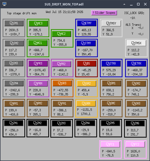
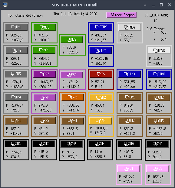
We've gone through all the suspensions and restored the alignment sliders to what they were yesterday (around 2026/07/16 04:11:58 UTC) before the power outage. All slider values have been SDF'd and all is good slider/sdf-wise by 1468256527 (Jul 16 2026 17:01:49 UTC).
A quick look at pointing shows that even though the sliders are all restored, many suspensions have different pointing. Here's a quick look at the difference between most of the suspension pointing before vs after the power outage after restoring OPTICALIGN OFFSETs. Both of these sets have the same offset slider values. Note that at this time the ISIs and HEPIs are all still down.
Once the SEI system is back up I'll be starting to adjust suspension pointing for those that don't match where they were yesterday by adjusting the slider values to get DAMP_IN (driftmon) back.
TITLE: 07/16 Day Shift: 1430-2330 UTC (0730-1630 PST), all times posted in UTC
STATE of H1: Planned Engineering
OUTGOING OPERATOR: None
CURRENT ENVIRONMENT:
SEI_ENV state: MAINTENANCE
Wind: --
Primary useism: --
Secondary useism: --
QUICK SUMMARY:
We had a power glitch at 06:01, most probably due to an electrical storm.
Richard and Gerardo are on-site recovering FAC and VAC.
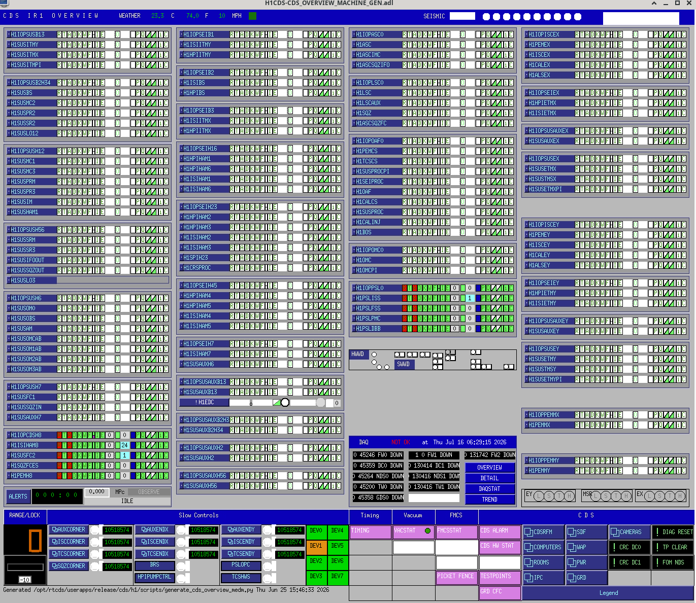
CDS status: both main DAQ legs are down. All front ends are down. NDS3 (vacuum trends) is up.
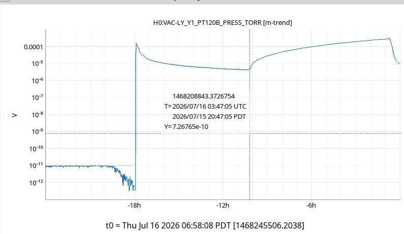
Gerardo reports that all three turbos on the main volume tripped last night. Attached trend of PT120B shows pumpdown starting 13:07 PDT yesterday afternoon, pressure starts increasing around 20:45 last night and recovery start 06:14 this morning
Jonathan, Erik,
Per WP 13402 the h1daq 0 systems where update to remove the dolphin interconnect and use ethernet.
The work plan is in T2600271. The basic work flow:
* Redirect nds queries to h1daqnds1
* Move the nds2 and ngdd data feeds to the 1 leg.
* I was unable to get the ngdd services properly running on h1daqkc1. I will look into this later.
* power down the systems.
* remove the dolphin cards, add in the ethernet nics as needed (some systems already had enough nics)
* reconfigure the networking.
* update the dns to drop gds0.
* start and test services.
We moved the h1daqscript0 to a temporary location so that we could mount sw-msr-daqd1. After we convert the daqstat ioc to a container we will be able to retire that machine. Pending daqstat updates I have re-enabled the dc0_epics_mirror and added a dc1_epics_mirror so that we can see the gds broadcast crc. Note even though the system shows a h1daqgds0 and h1daqgds1 those systems are gone, and the broadcast is being done from dc0 and dc1.
I finished off WP 13401 by configuring the frame writers to use the run number server on in the container cluster. This will be tested at the next daqd restart.
We still need to pull the dolphin switches out of the racks.
Then there is OS upgrades for the daqd systems.
M. Todd, C. Compton, T. Shaffer
We had a go today at pointing the FLIR Boson+ camera at ITMY with the ring heaters on at 2W per segment. In short, we were not able to see anything with the FLIR Boson+ yet. My feeling is that the camera should definitely be able to see it, as we pointed another hand-held FLIR and were able to see a bright spot where we though the test mass was (though it was pretty out of focus because the hand-held is not as great as the Boson+). The issue with the current setup is the camera pointing is not easily adjusted, and did sit centered in the camera can that we were able to fit on the viewport.
The setup with the guillotine was to take the back off of a camera can and mount the camera in there as best we could without anylenses to maximize our field of view. Then we attached the camera can and removed the guillotine to look at the ITM. We tried removing the background because the image seemed completely saturated as if it was catching a reflection from something. We tried adjusting the aperture to reduce this but had no luck. We tried removing the camera can and pointing the handheld FLIR at the ITM and saw a bright spot that looked like it could be the ITM, so we tried again with the camera can slightly rotated to see if the seating in the camera can was an issue --- again without any luck.
Overall, I think it deserves another test using a pitch-yaw mount or something and a little bit smaller footprint so that it fits in the camera can more easily. Additionally, we should see what the lenses are for the other cameras used pointing at the ITMs, as they will probably be useful.
I also found a Windows GUI that interfaces with the camera a little more customizably, which may be useful for future tests as well.

ITMY has been turned back off to 0W /segment, this is nominal.
Wed afternoon Nergis and I went to SQZT7 to get a couple of beam profiles after the ZM4 preload was adjusted, before the ZM5 swap.
We took two measurements with the same psams settings but different centering on ZM2, based on what Camilla and Madi did in 90946 . The data labeled as nominal position is for these sliders where Camila reports that the beam on ZM2 is 5.85" off the table, and the data labeled raised is for these sliders where the beam is actaully lowered to 5.75". The center of ZM2 should be 5.5" off the table. M^2 went from 1.35 to 1.28 horizontal and 1.25 vertical with the improved centering, and the relative astigmatism also improved from 0.13 to 0.02 Ryan found the definition of relative astigmatism on page 122 (pdf page 129) of the BC207 manual here.
ZM4 strain guage was saturated when the PZT was much above 100V, so this morning Daniel came to SQZ racks with Ryan and I and changed some resistors, Daniel will add the details. ZM4 strain guage is now working well, with values between -4.1V to 2.7V, and Ryan turned the servo back on.
Yesterday morning, I noticed that for some psams settings, the beam was clipping on the top periscope mirror and that then we measured quite high M^2 values. I wondered if clipping on that persicope could explain more of our M^2 measurements. Today Ryan Short and I carefully aligned the psams to get the beam centered on the two irises on SQZT7. We raised the top periscope mirrors, and Ryan adjusted both periscope mirrors to get the beam well centered on the irises again. When we did this, we noticed that only one of the bolts that holds the top periscope mount to the periscope structure was tight.
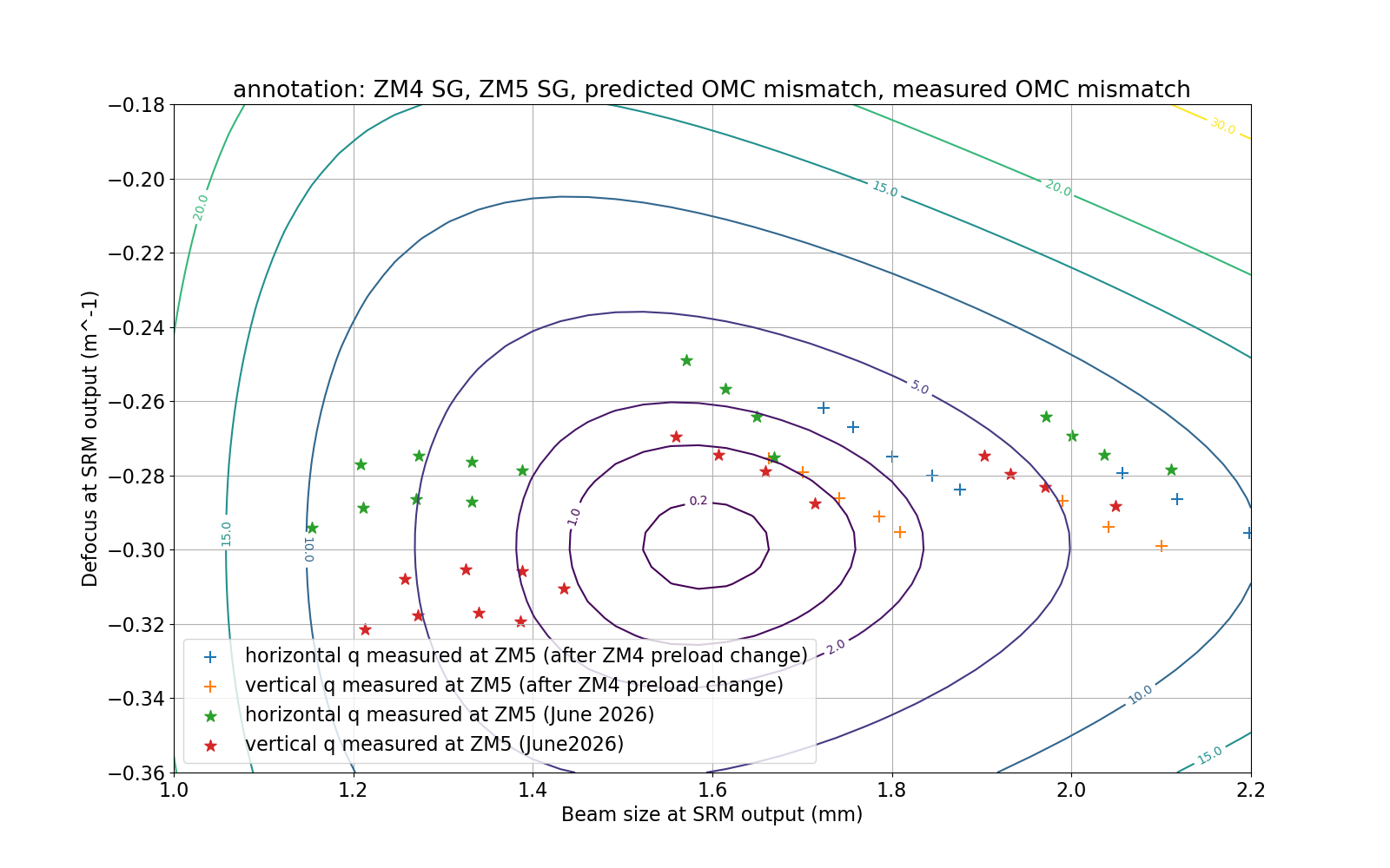
After this Ryan and I did another round of profile measurements with the new preload and working strain guage on ZM4. We took 5 points over the range of ZM4 with ZM5 PZT at 100V, with the ZM5 strain guage not working, then took 3 points with ZM5 at a strain guage of -4.5V which is 20V on the PZT, because the ZM5 strain guage is working there we can compare these to measurements taken before ZM5 stopped working.
Unfortunately, even after moving the periscope mirror the M^2 values are in the range of 1.4 to 1.23, so the clipping on the periscope mirror wasn't the explanation for the high M^2
The little box attached to the PSAMS driver for ZM4 had a 88.6K and a 751 Ohm resistor in series between pins 11 and 24 (sstrain gauge readout and ground). This was replaced by a 227K resistor to better balance the bridge circuit.
Here is a plot of the data taken after the ZM4 preload adjustment. The line of 5 new points was taken with the ZM5 PZT at 100V, where the strain guage wasn't working, which doesn't correspond to any of the strain guage values from the previous data set. The 3 points taken at ZM5 strain guage at -4.5V should corresond to the previous ZM5 setting that thery are near. It would be very helpful to get this data for ZM5 values closer to good mode matching, but at first glance it seems like the ZM4 pre-load change moved us in the correct direction.