Jennie W, Daniel S, Jeff K,
Human Readable Summary:
Today I finished doing the last round of changes to ascimc.mdl which adds a path to do ASC for the new jitter attenuation cavity, JAC. As part of this, the IMC will no longer be using the PSL periscope PZT as a feedback path to control input alignment and instead this path will be used to align to the JAC. We have implemented logic in the IMC ASC model to use the IMC as normal just now. We have also put in the infrastructure in this model for the JAC ASC in a JAC top_names block. The JAC has 2 WFS, 1 RF PD as input and feeds back to the PSL periscope and JM1 tip-tilt suspension for alignment. These changes were built and added to the re-locked revision in the svn.
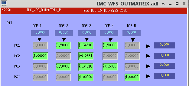
Details for the IMC: We have added a line to the output matrices of the IMC (old P and Y in medm) where the final fifth line is used to send signals to the new JM3 tip-tilt which will be installed in HAM1 during the vent downstream of the JAC and upstream of the IMC, these currently contain zeros in the fifth line but I haven't updated the medm screen for IMC_WFS yet. The ASCIMC model now contains send PCIe modules whoch correspond to the recieve modules in the SUS-JM3 model.
There is also a switch H1:ASC-IMCJAC_PZTOUTSW in the top level of the ASC IMC model to switch between the JAC servo using the periscope PZT as a feedback path (switch OFF) and the IMC servo using the PZT as a feedback path (switch ON). This has been saved in safe SDF snap file in the ON state which means the IMC should work as expected until we have the JAC installed.
I have uploaded a pic here and here of the changes made to the top level in H1ascimc.
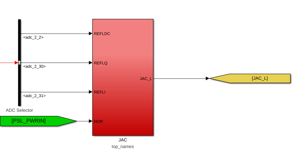
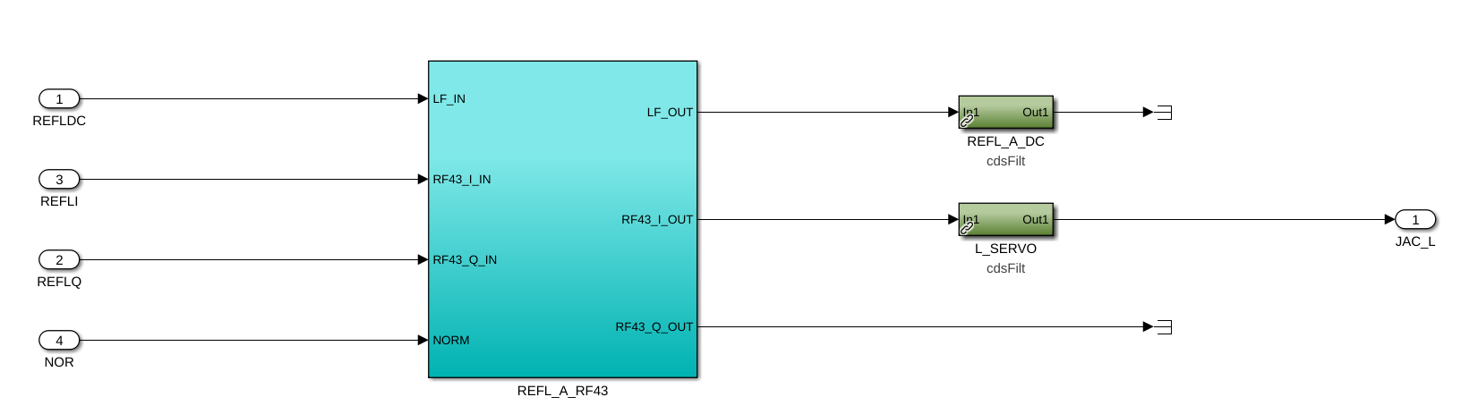
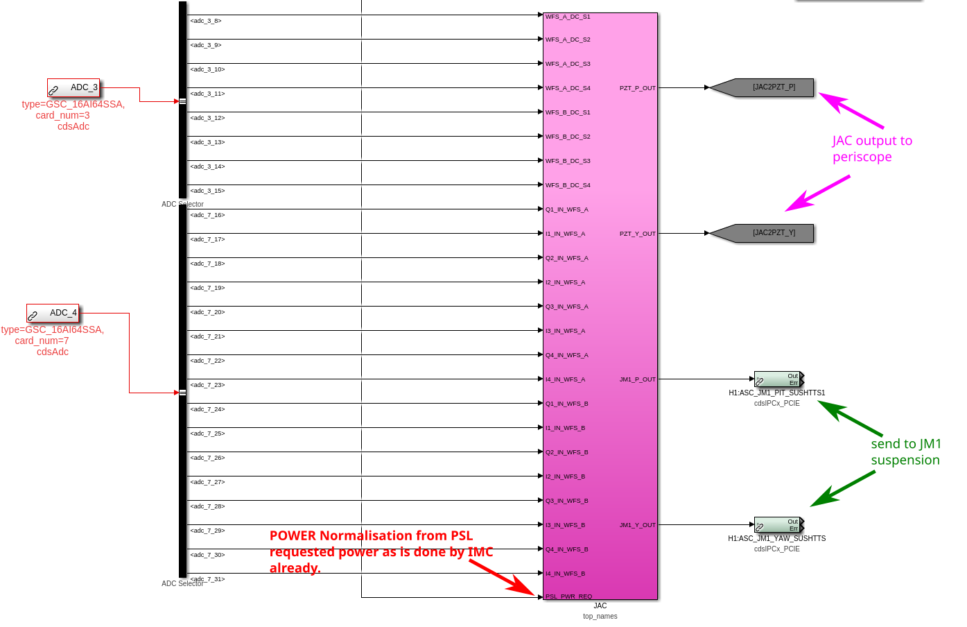
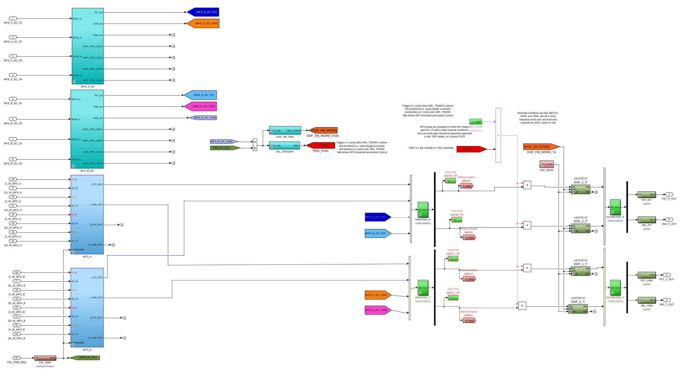
Details for the JAC ASC: In the JAC top_names block we have the attached architecture. This has standard library blocks for the A and B JAC in-air WFS and the DC readouts of each these.
The controls are copied from the IMC model but with 2 degrees of freedom instead of 5. I have also skipped the dither locking controls as we don't seem to currently use this in the IMC.
Details for h1sqz model:
Four squeezer channels were added to h1ascimc model and removed from the h1sqz model are:
H1:SQZ-OPO_SERVO_EXC
H1:SQZ-SHG_SERVO_EXC
H1:SQZ-LO_SERVO_EXC
H1:SQZ-CLF_SERVO_EXC
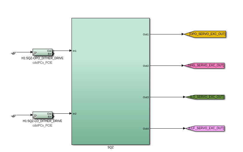
- two are sent from the SQZ model, H1:SQZ-OPO_DITHER_DRIVE and H1:SQZ-LO_DITHER_DRIVE, they go into a SQZ block.
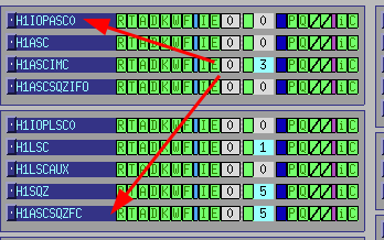
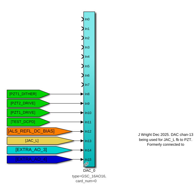
This block contains these filter banks, which we transferred from the h1sqz model. SHG_SERVO_EXC and CLF_SERVO_EXC have grounded inputs like they did the h1sqz model. The outputs are sent to the DAC0 channels highlighted with a green dotted line in this image of the h1ascimc model.


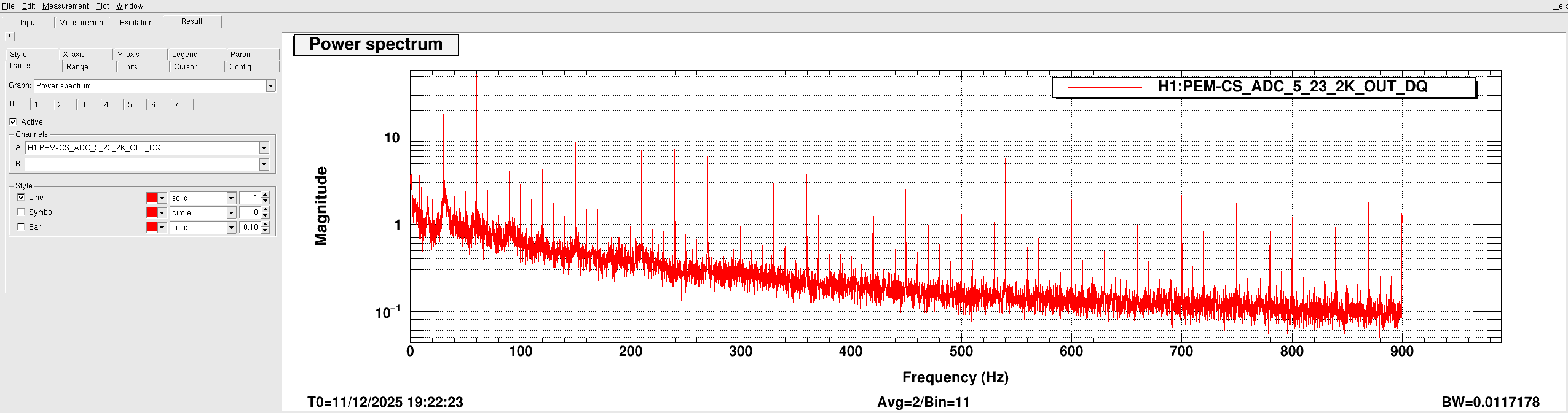
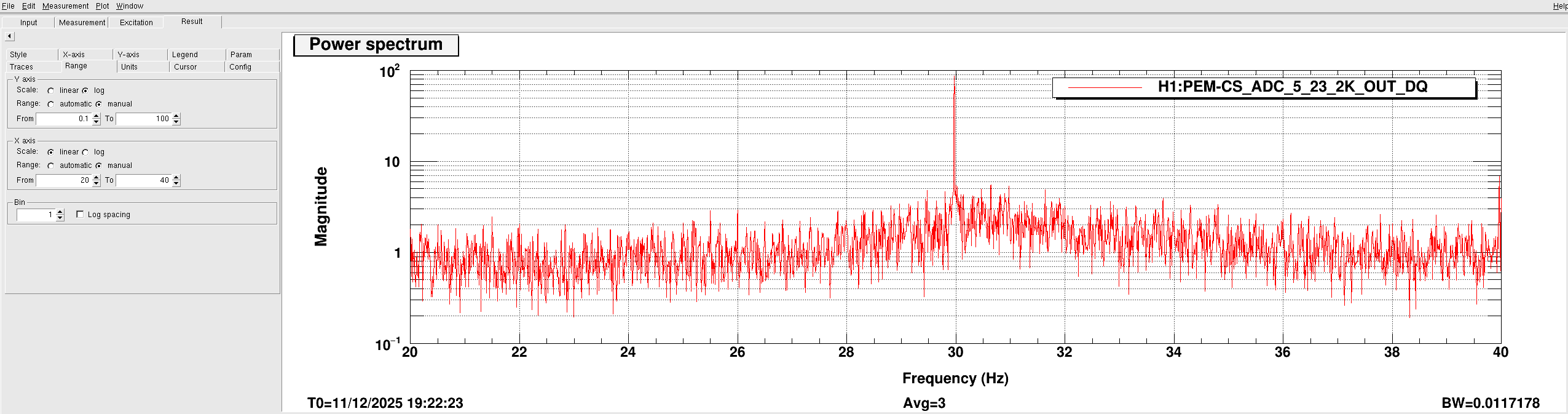
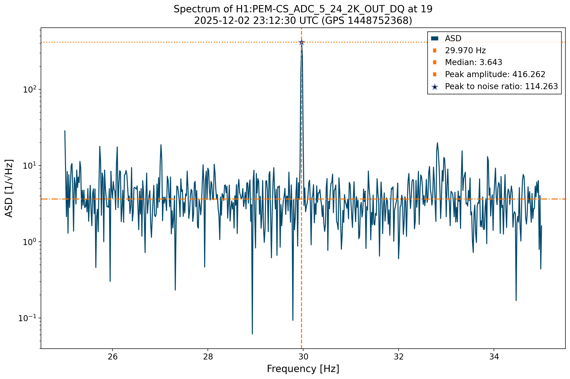 That is, we compute the ASD using 60s FT and check the amplitude of the ASD at the frequency of the first harmonic of the largest of the near-30 Hz combs, the fundamental at 29.9695 Hz. Then, we compute the median of the +- 5 surrounding Hz and save the ASD value at 29.9695 Hz "peak amplitude" and the ratio of the peak against the median to have a sort of "SNR" or "Peak to Noise ratio".
Note that we also check the permanent magnetometer channels. However, in order to compare them to the rest, we multiplied the ASD of the magnetometers that Robert gave us times a hundred so that all of them had units of Tesla.
After saving the data for all the positions, we have produced the following two plots. The first one shows the peak to noise ratio of all positions we have checked around the LVEA and the electronics room:
That is, we compute the ASD using 60s FT and check the amplitude of the ASD at the frequency of the first harmonic of the largest of the near-30 Hz combs, the fundamental at 29.9695 Hz. Then, we compute the median of the +- 5 surrounding Hz and save the ASD value at 29.9695 Hz "peak amplitude" and the ratio of the peak against the median to have a sort of "SNR" or "Peak to Noise ratio".
Note that we also check the permanent magnetometer channels. However, in order to compare them to the rest, we multiplied the ASD of the magnetometers that Robert gave us times a hundred so that all of them had units of Tesla.
After saving the data for all the positions, we have produced the following two plots. The first one shows the peak to noise ratio of all positions we have checked around the LVEA and the electronics room:
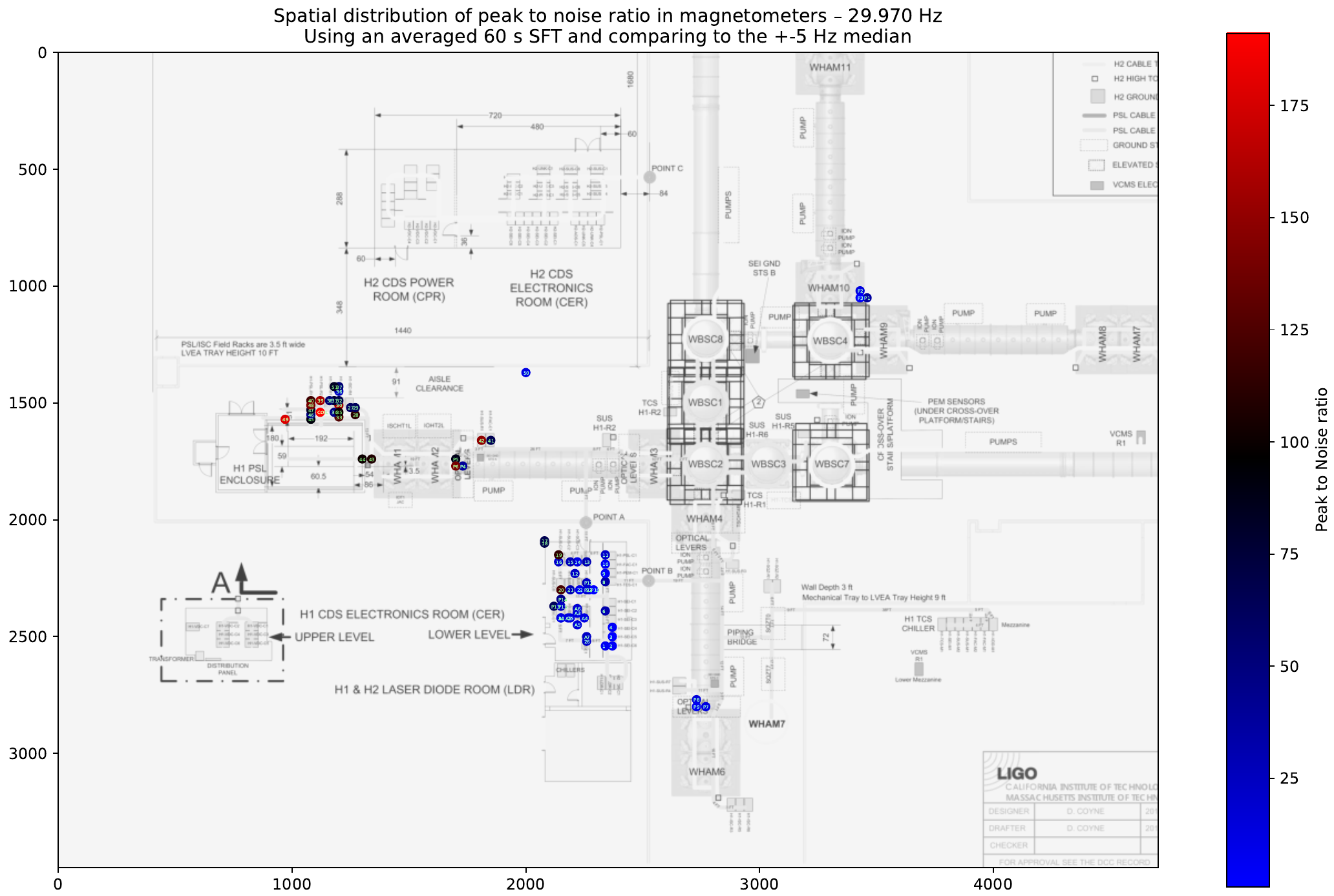 Where the X and Y axis are simply the image pixels. The color scale indicates the peak to noise ratio of the magnetometer in each position. The background LVEA has been taken from
 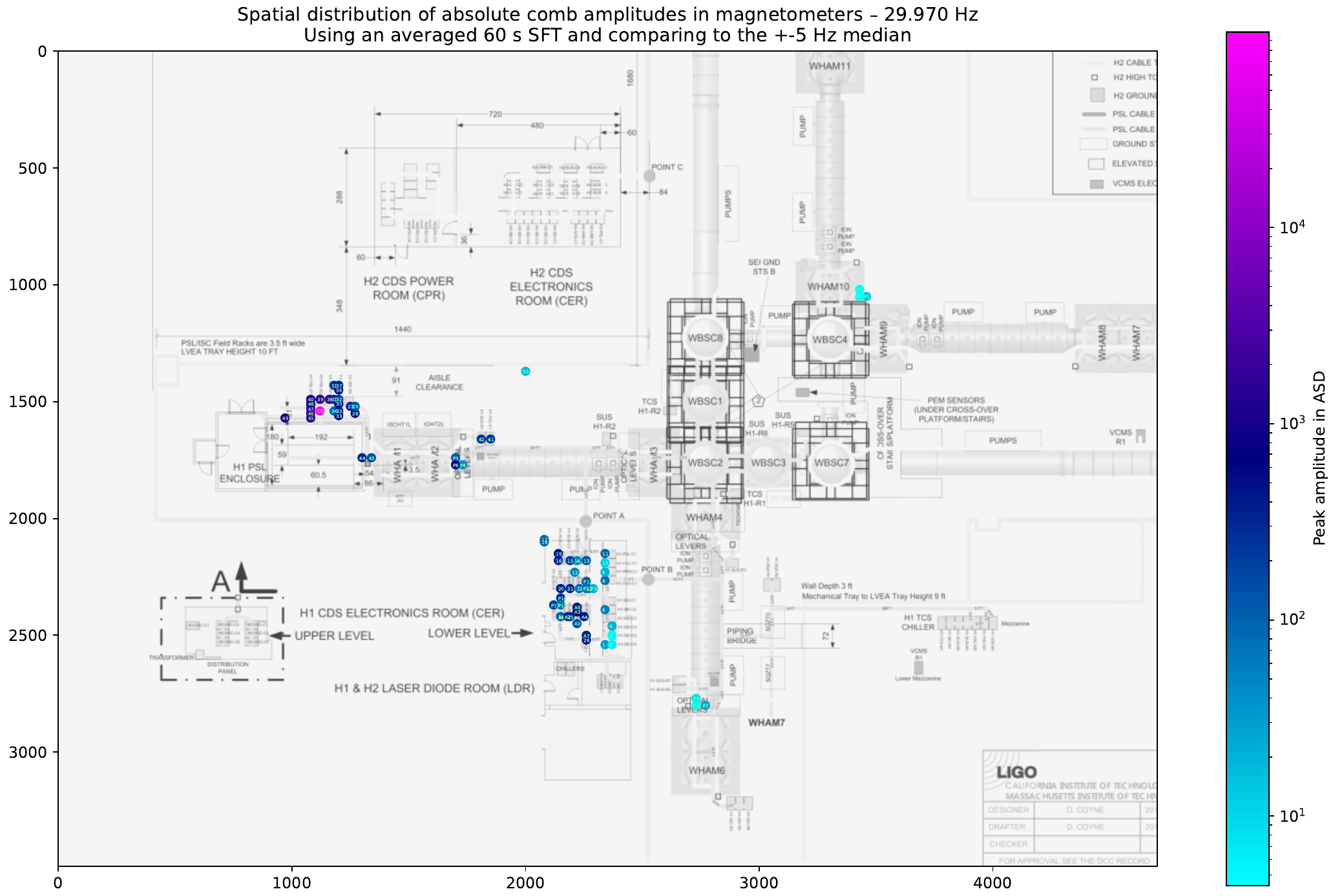 Note that in this figure, the color scale is logarithmic. It can be seen how, looking at the peak amplitudes, there is one particular position in the H1-PSL-R2 rack whose amplitude is around 2 orders of magnitude larger than the other positions. Note that this position also had the largest peak to noise ratio.
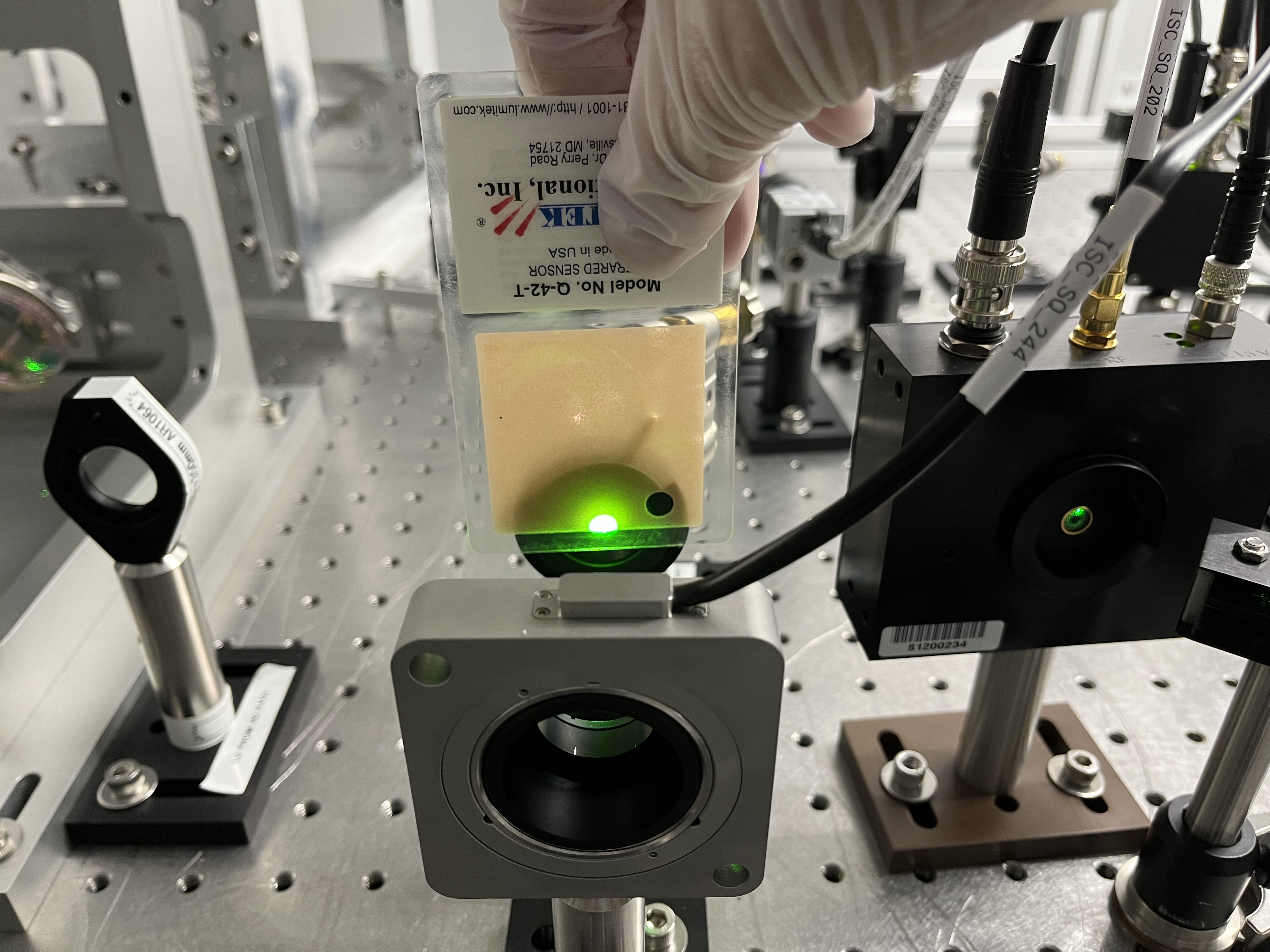
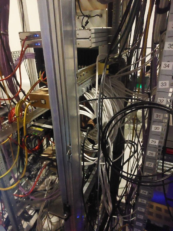
This position, that we have tagged as "Coil", is putting the magnetometer into a coil of white cables behind the H1-PSL-R2 rack, as shown in this image:
Note that in this figure, the color scale is logarithmic. It can be seen how, looking at the peak amplitudes, there is one particular position in the H1-PSL-R2 rack whose amplitude is around 2 orders of magnitude larger than the other positions. Note that this position also had the largest peak to noise ratio.
This position, that we have tagged as "Coil", is putting the magnetometer into a coil of white cables behind the H1-PSL-R2 rack, as shown in this image:
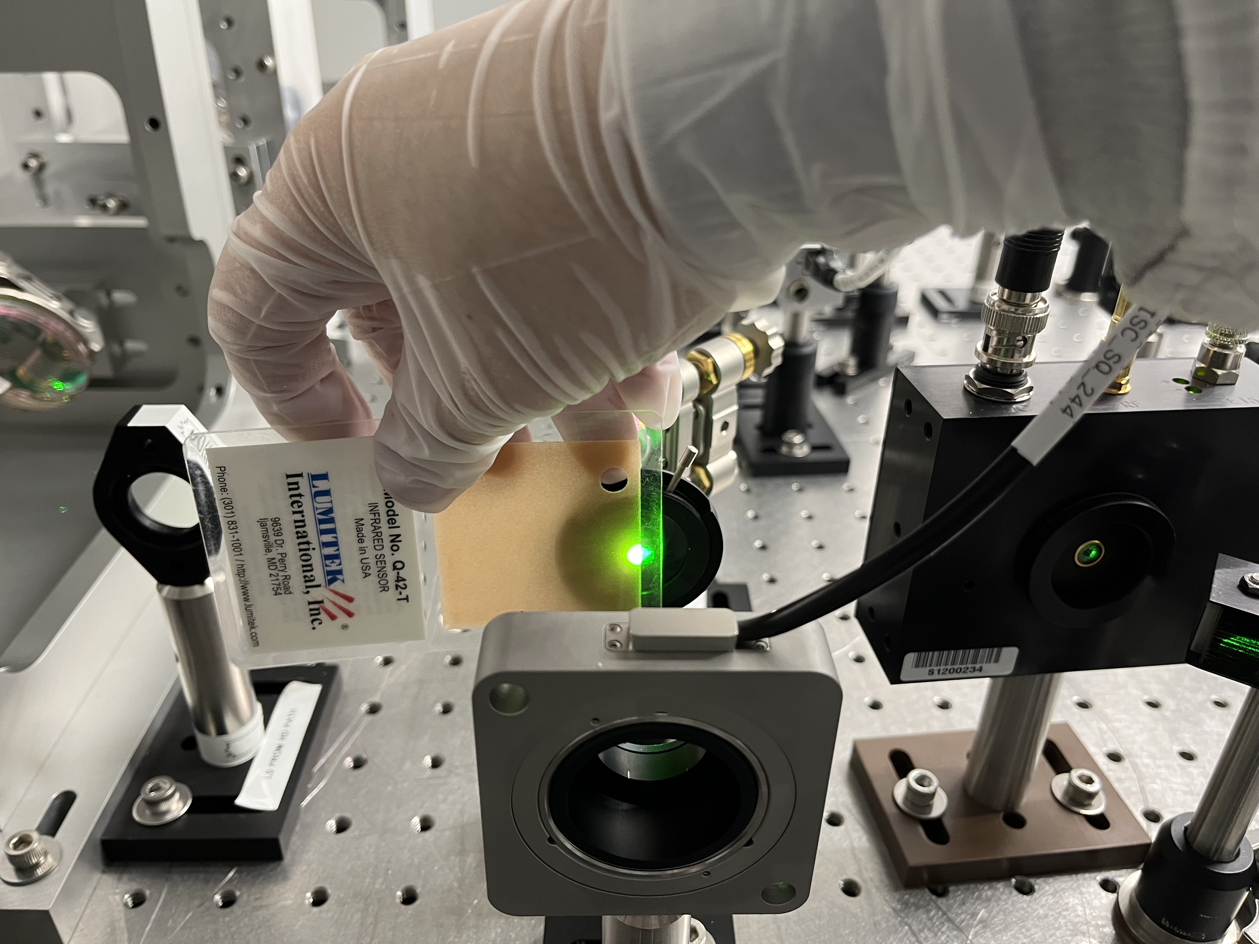
 The reason that led us to put the magnetometer there is that we also found the peak amplitude to be around 1 order of magnitude larger than on any other magnetometer on top of one set of white cables that go from inside the room towards the rack and up towards we are not sure where:
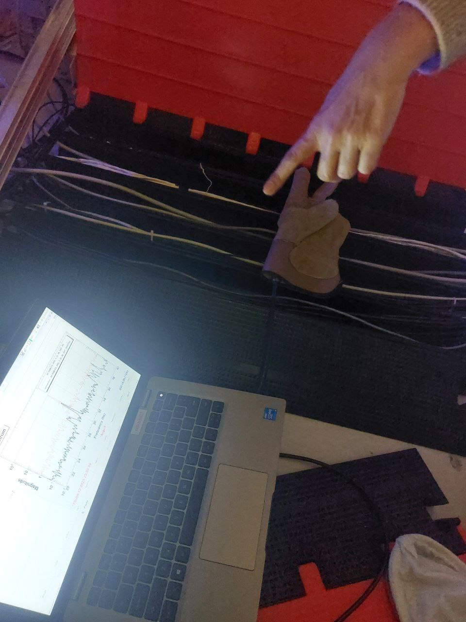 This image shows the magnetometer on top of the cables on the ground behind the H1-PSL-R2 rack, the white ones on the top of the image appear to show the peak at its highest. It could be that the peak is louder in the coil because there being so many cables in a coil distribution will generate a stronger magnetic field.
This is the actual status of the hunt. These white cables might indicate that the source of these combs is the different interlocking system in L1 and H1, which has a chassis in the H1-PSL-R2 rack. However, we still need to track down exactly these white cables and try turning things on and off based on what we find in order to see if the combs dissapear.
This image shows the magnetometer on top of the cables on the ground behind the H1-PSL-R2 rack, the white ones on the top of the image appear to show the peak at its highest. It could be that the peak is louder in the coil because there being so many cables in a coil distribution will generate a stronger magnetic field.
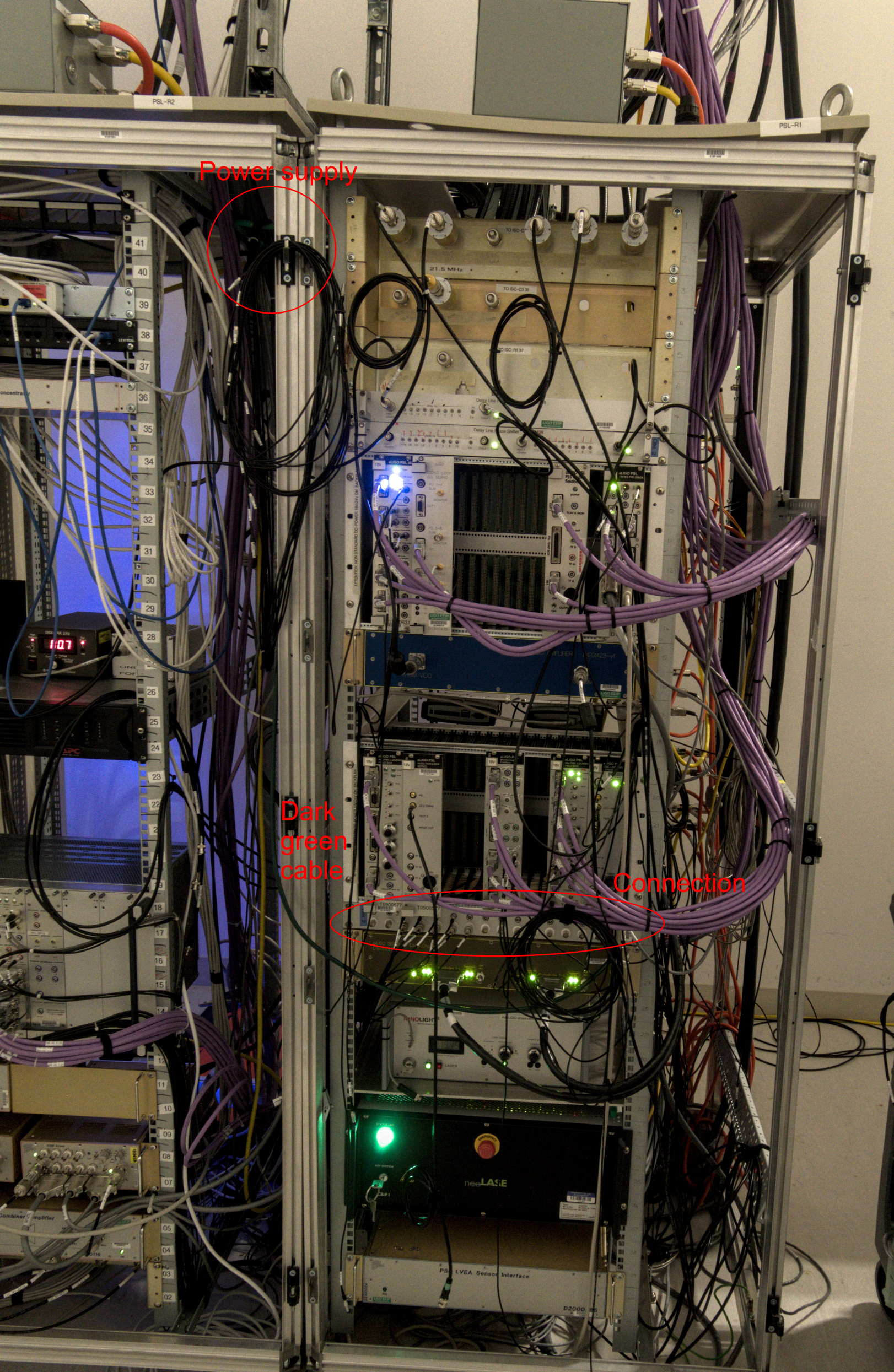
This is the actual status of the hunt. These white cables might indicate that the source of these combs is the different interlocking system in L1 and H1, which has a chassis in the H1-PSL-R2 rack. However, we still need to track down exactly these white cables and try turning things on and off based on what we find in order to see if the combs dissapear.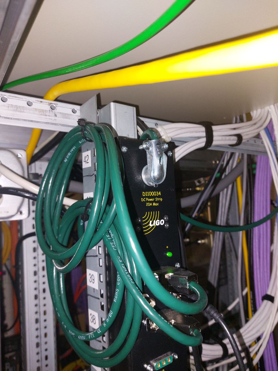 So it may be that these lines may be transmitted elsewhere through this power supply.
We connected a voltage divider and connected it to the same channel we were using for the magnetometer (H1:PEM-CS_ADC_5_23_2K_OUT_DQ):
So it may be that these lines may be transmitted elsewhere through this power supply.
We connected a voltage divider and connected it to the same channel we were using for the magnetometer (H1:PEM-CS_ADC_5_23_2K_OUT_DQ):
 Out of this power supply, two dark green cables come out, the first one goes to the H1-PSL-R1 rack:
 However, the comb did not appear as strong when we put the magnetometer besides the chassis where the cable leads.
On the other hand, the comb does appear strong if we follow the other dark green cable, that goes to this object
However, the comb did not appear as strong when we put the magnetometer besides the chassis where the cable leads.
On the other hand, the comb does appear strong if we follow the other dark green cable, that goes to this object
 Which Jason told us it may be related to the interlock system.
Following the white cables that go from this object, it would appear that they go into the coil, where we saw that the comb was very strong.
We think it would be interesting to see what here can be turned off and see if the comb does disappear.
Which Jason told us it may be related to the interlock system.
Following the white cables that go from this object, it would appear that they go into the coil, where we saw that the comb was very strong.
We think it would be interesting to see what here can be turned off and see if the comb does disappear.
We eventually lock TR_CARM by going through the guardian steps slowly. We noticed that when we stepped through slowly, the ALS COMM VCO would pull the mode cleaner away causing the TR_CARM path to rail. We disabled the VCO internal servo that uses the frequency comparator to keep the VCO at a fixed frequency. This has been used in the past for our sucsesful transitions, but seemed to be railing each time this morning.
We left the ALS not shuttered, and ran the QPD servos while ASC and soft loops were engaged, with Tony acting as a SRC1 servo. After all the ASC had engaged, the camera set points still looked good, I set the QPD offsets back to their values from SDF, and the camera offsets still looked good. The guardain has been reset to shutter ALS as normal next time we relock. The POP A yaw offset was off slightly, I set it to -0.43 rather than -0.4.
We then transitioned to DC_READOUT using the guardian without any intervention, or known fixes for the problems we were having.
We are able to turn on the SRC1 yaw loop, but the SRC1 pitch loop pulls the side band build ups off. I've added the SRC1 yaw loop back into ENGAGE_ASC_FOR_FULL_IFO.
Re: Matt's alog this morning, I was worried that we had a sticky slider situation after the beckhoff work (which apparently isn't really a thing here, but was a thing at the 40m). We moved sliders and flipped switches on the IMC common mode board, the IFO REFL common mode board, and the summing node. Probably that wasn't the issue.
After a few other TR_Carm unsuccessful attempts, I trended and it turns out that the time we had been successful doing things by hand that Sheila mentions, we had forgotten to turn off the H1:ALS-C_COMM_PLL_BOOST, so we did the whole transition with the boost left on. I have now set in the guardian to leave the boost on, and we have now gotten through this several times without any intervention. I also added turning off the ALS COMM VCO by clicking the Ext button (and resetting it to Int in PrepForLocking), however it's possible that that wasn't necessary, since guardian already had changing the On/Off switch as part of these states. The real key seems to be leaving on the H1:ALS-C_COMM_PLL_BOOST.
As Sheila said, DC readout seems to just be working fine, no intervention needed. Total mystery why it hadn't been working on Tuesday.
We have now powered up to 25 W two times! Even if we're not able to get farther than this, there are very few items left that would need to be checked using the full IFO (eg, the ISS second loop can be checked using IMC-only).
SRC1 P is still out of the guardian. One time I was able to close it using the offset from lownoise ASC, at Elenna's suggestion. But, we still lost lock in MoveSpots. The other time I was by-hand watching SRM pitch. No need to move it up to 25W, and I think I picked the wrong direction during move spots, so we still lost lock.
We got up past 25W a third time. This time, rather than doing MOVE_SPOTS, I manual-ed and did RF9 and then RF45 modulation depth reduction. Both of those were fine, although the 45 MHz reduction did confuse my Jenne-in-the-loop SRM alignment loop. At some point, it became clear that SRC1 yaw was pulling us away, so we turned that off and I started dealing with SRM yaw alignment as well as SRM pit alignment. We then did move spots with both SRC1 pit and yaw open and me watching them. That seemed fine. We then started going to MAX_POWER. I think we got up to 50W, but then we got a nasty ASC ringup and lost lock.
The only analog things that we haven't tested yet are (I think) coil driver switching, ESD switching, and OMC whitening switching, and ISS Second loop engagement. Tony had checked PCals earlier in one of our locks, and they were fine.
It sounds like there will be some folks around to perhaps try locking again tomorrow. However, as Betsy pointed out, now we have a pretty small list of things that *haven't* been tested, so even if we aren't able to get to full NLN we have very few things to be suspicious of when relocking next calendar year after the vent. ISS second loop we can test using IMC-only. Anamaria and Jeff were thinking through how could we check (using, eg, the IMON channels) the sus actuator switching. I think that we could also try OMC whitening switching using a single-bounce OMC.
Due to it giving Jenne trouble and pulling alignment away, I have commented out SRC1_Y from ENGAGE_ASC. This means the "human servo" will need to be in-use for now for SRM, especially during powerup and the spot move.
I've attached the ASC trends around where the ringup happened during the powerup. Looks like this is the known ~0.45 Hz instability and it's possible we were just unlucky.
The plan for tomorrow is to start locking just like we did this last time (fully auto with someone monitoring SRM alignment) and see how far we can get. If we're unable to fully reach low noise, there are ways we can check certain systems for functionality before we plan to close the arm gate valves mid-afternoon.