This morning after Fil switched ON the ESD HV on EX (EY was already ON), I took the OPLEV charge measurements on ETMX and ETMY. I will post the results after processing the data.
Both the suspensions were restored after the measurements were complete.
Also, I noticed that on ETMX the amplitude of L3 calibration lines was set to zero since Jan 16, 2024 (when last measurements were taken), I have set it to the nominal value of 0.12 after trending it.
I ran the analysis this morning for the OPLEV charge measurements that Rahul took on Tuesday.
For ETMX, the charge is trending down towards zero on all DOF & Quads!
For ETMY, the charge appears to be mostly stable around zero with some small uptrends on LL & UL and only on LL (P&Y) the charge is just above 50[V].
HWS and CO2 lasers turned back on this morning. I swapped the HWS camera power supply cabling back to the "quieter" ungrounded verison (75876).
CO2Y came back with less power than expected (388W when we had 42W before the break), TJ and I increased the temperature step point and we now have 40.6W out of the laser head. Plot attached. We might think about slowly stepping the temperature to see if we can find a better operating point.
This is not worrying: in 65277 we show can inject ~16% of power out of laser into the vacuum through the annular mask. Expecting we continue observing with 1.7W, we only need ~10W from the head.
TJ and I restarted HWS code on both ITMX and ITMY with camera frequency 1Hz for X, 10Hz for Y (lowest frequency that doesn't saturate pixels).
New references taken. Ring heaters are at their nominal settings, 0.44W/segment on ITMX, 0W on ITMY.
We had to restart h1msr1 and try starting the code multiple times to avoid a segmentation fault in ITMY. We checked the wave fronts and removed a bad pixel from ITMX. ITMY crashed after running for ~10 minutes, we restarted it but we should check on it later.
Attached is the HWS plot of the location of CO2Y.
The ESD HV power supplies and Low Voltage Chassis were powered on at EX. Needed for charge measurements.
J. Kissel, L. Dartez %%%%% Executive Summary %%%%%% Remeasured OMC DCPD electronics chain electronics, including compensation, post Jan/Feb OMC swap. There's a small, 0.3% drop in magnitude below 25 Hz. The first line of suspicion is that the environmental or electrical conditions surrounding the new style of transimpedance amplifier, even though the circuit and enclosure itself hasn't changed, but the investigation has just started. %%%%% More Info %%%%%% As y'all know, we swapped out the OMC in Jan / Feb 2024 (see highlights in LHO:75529). 
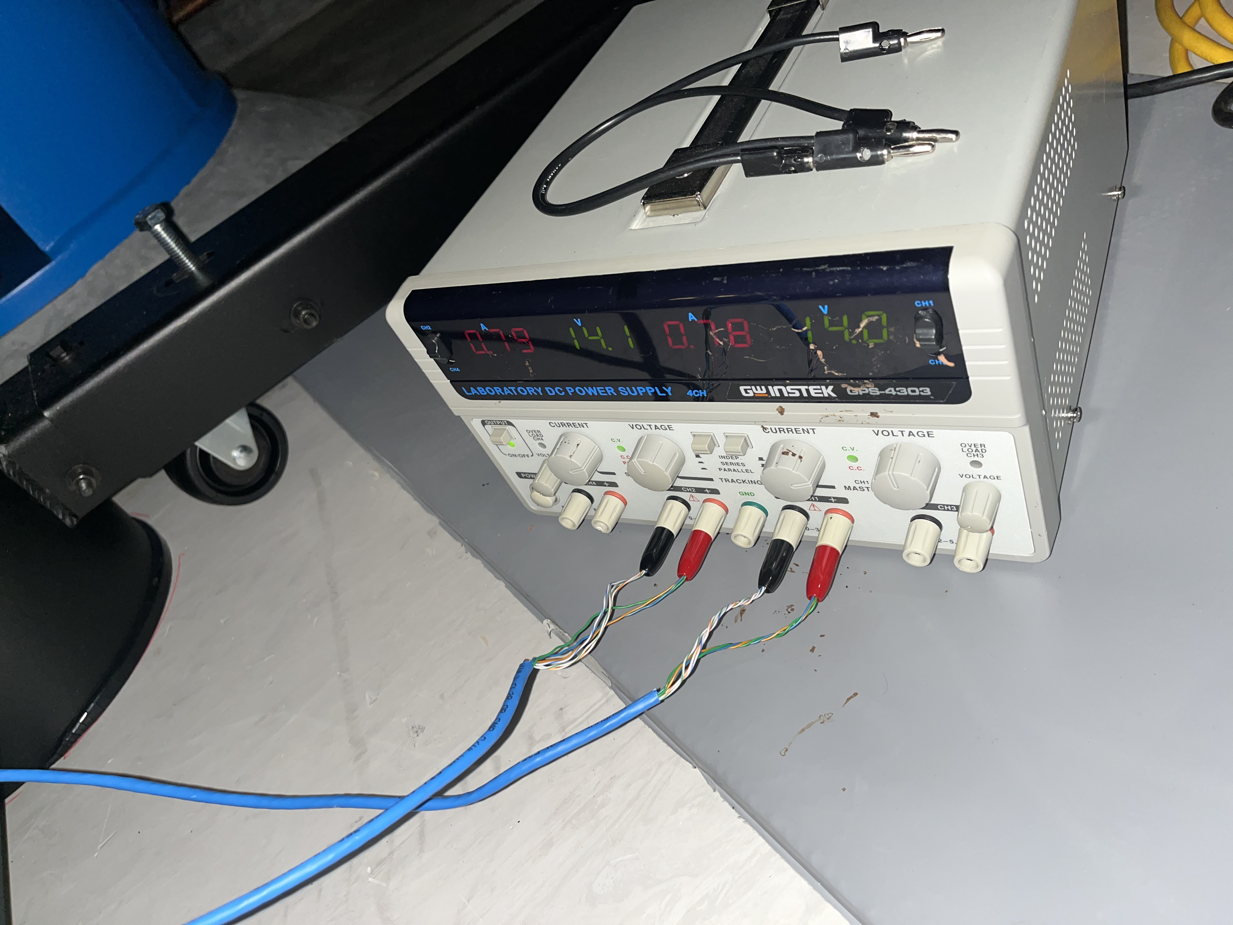
That means we have brand new gravitational wave DCPDs. However, it's *only* the DCPDs that have changed in the GW path. Remember, as of O4, the PD's transimpedance amplifier (TIA) is now inside a separate podded electronics box () that encloses a brand-new style of TIA (see T1900676 and G2200551). This need not -- and hasn't -- changed with the swap, where it used to need be changed because the TIA was built in to DCPDs in pre-O4 OMCs. So, in principle, we've "just" disconnected the old PDs, and reconnected the new PDs, to the same electronics. As such we don't *expect* the frequency response of the signal paths to change. However, Keita reports, for the first time in history, that there're no electrical issues with the OMC sensors after the OMC swap in January (LHO:75684). While there have not been issues with the DCPDs themselves, per se, recall, for example, problems in the past including issues with shorts to electrical ground of the OMC's PZTs (IIET:12445). Keita did report that, during this Jan/Feb 2024 vent that he found and mitigated some grounding issues with the preamp though -- the 3 MHz SQZ side-band pick off of the gravitational wave DCPDs had shown some signs of electrical short to ground. Quoted from LHO:75684: Inside the chamber on the in-vac preamp, the DB25 shell is connected to the preamp body (which is isolated from the ISI via PEEK spacer). At first DB25 shell and the preamp body was shorted to the ISI table, but this turns out to be via 3MHz cable ultimately connected to the in-air chassis. As soon as both of the 3MHz cables were discunnected from the in-air chassis, preamp body as well as the DB25 shell weren't conducting to the ISI table any more. I interpret this to mean that there's a *potential* that the electrical grounding on board the OMC and in the GW signal path of the TIA *has* changed from "there used to be an issue" to "now there is no issue." So with uber-careful, precision calibration group hat on, I repeated the remote, full-chain measurements of the OMC DCPD GW path -- including the digital compensation for their frequency response -- that I took on July 11 2023 -- see LHO:71225. 
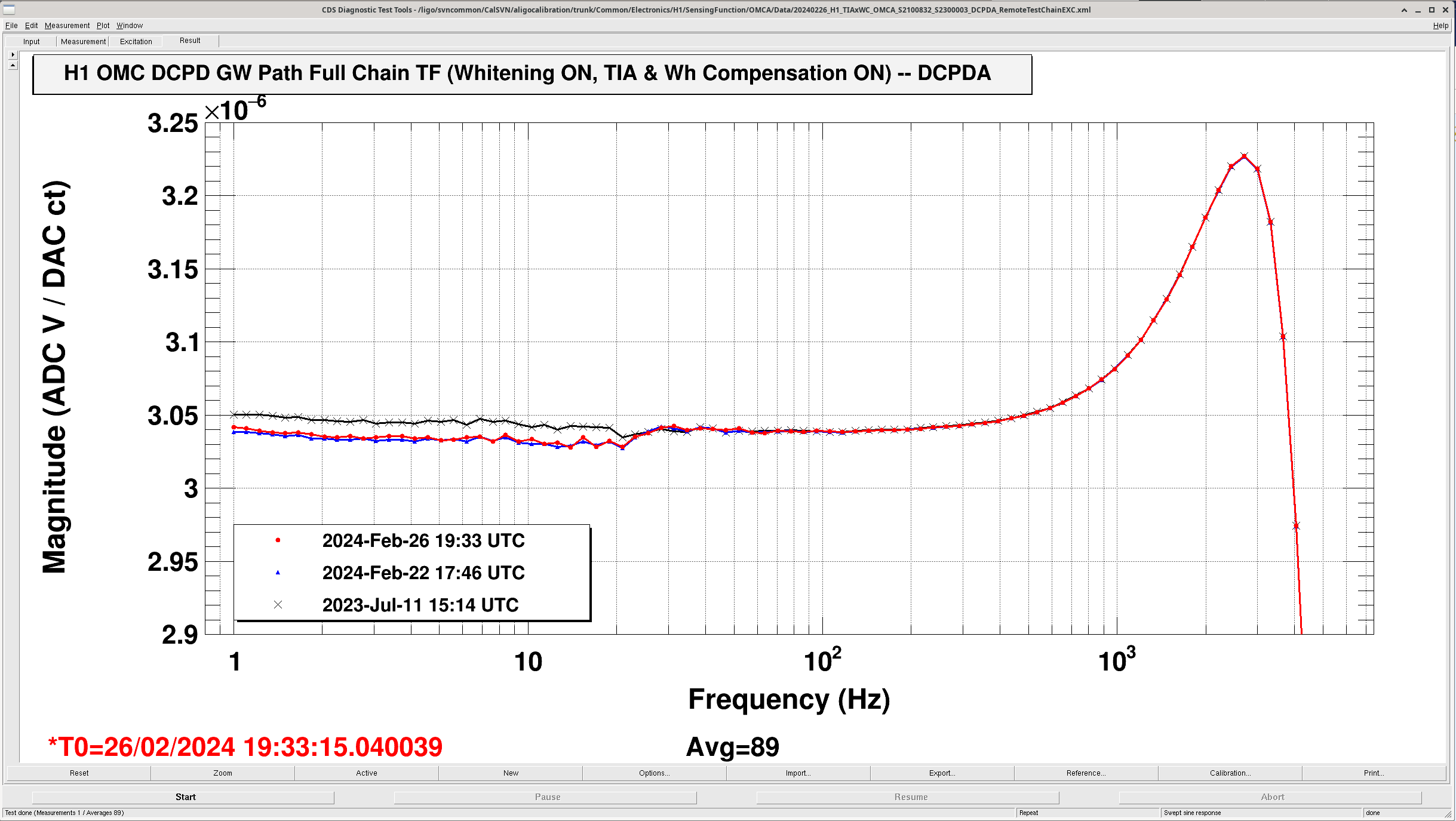
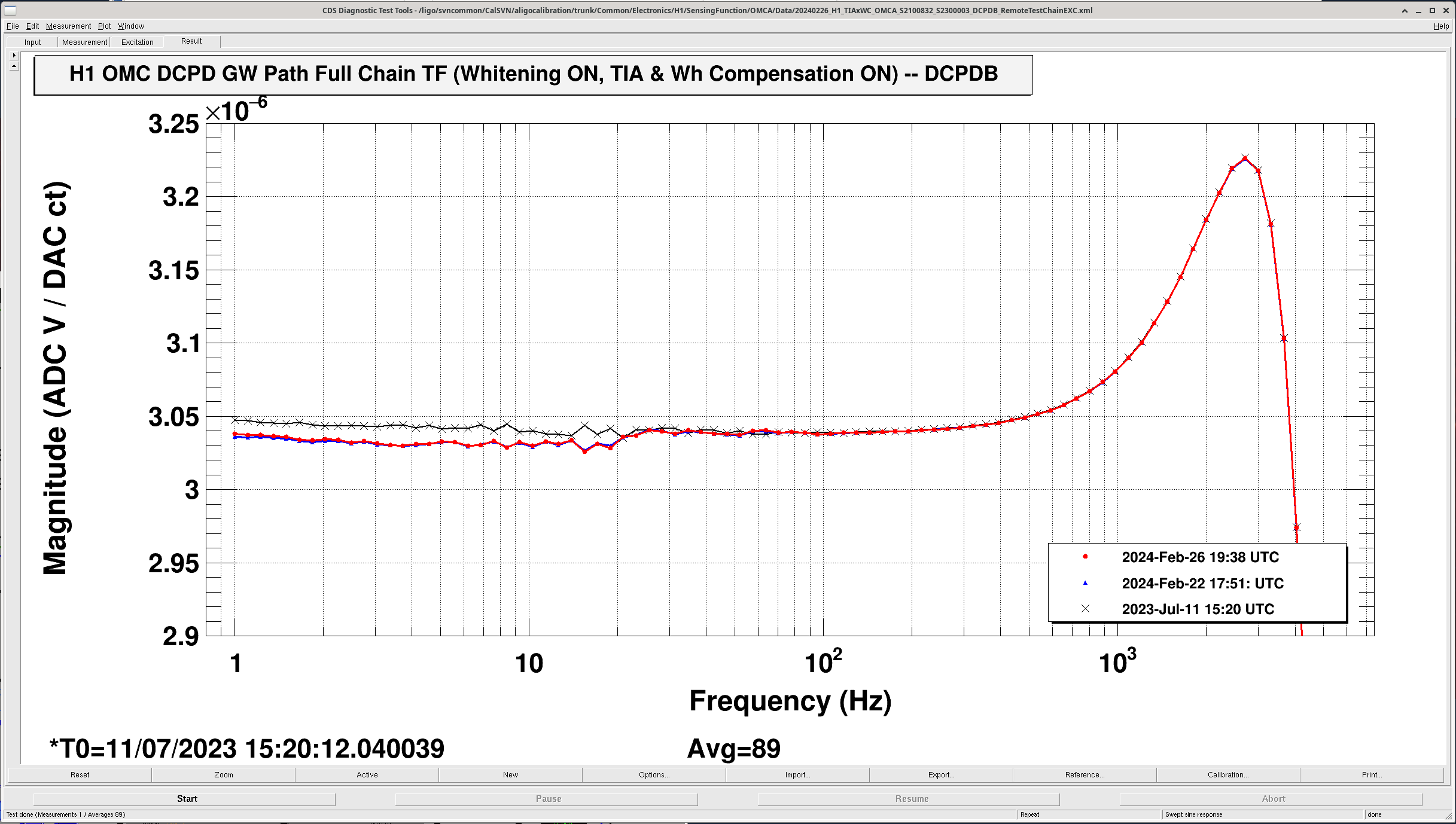
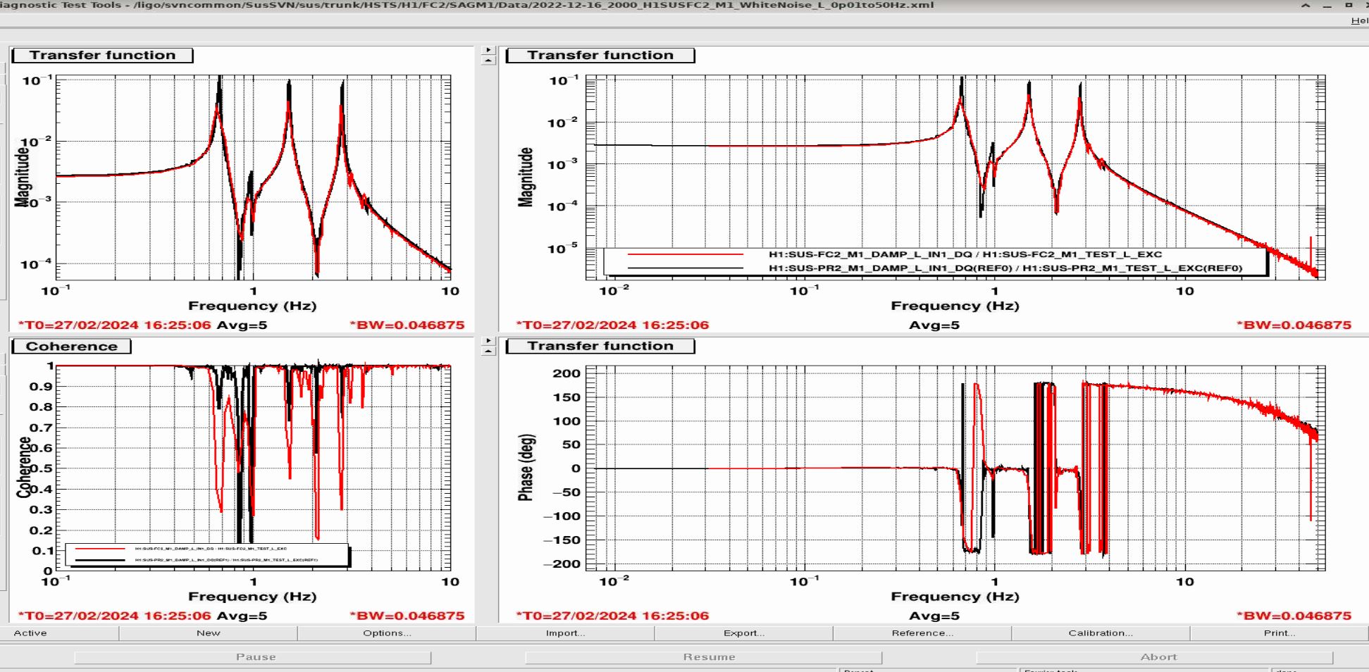
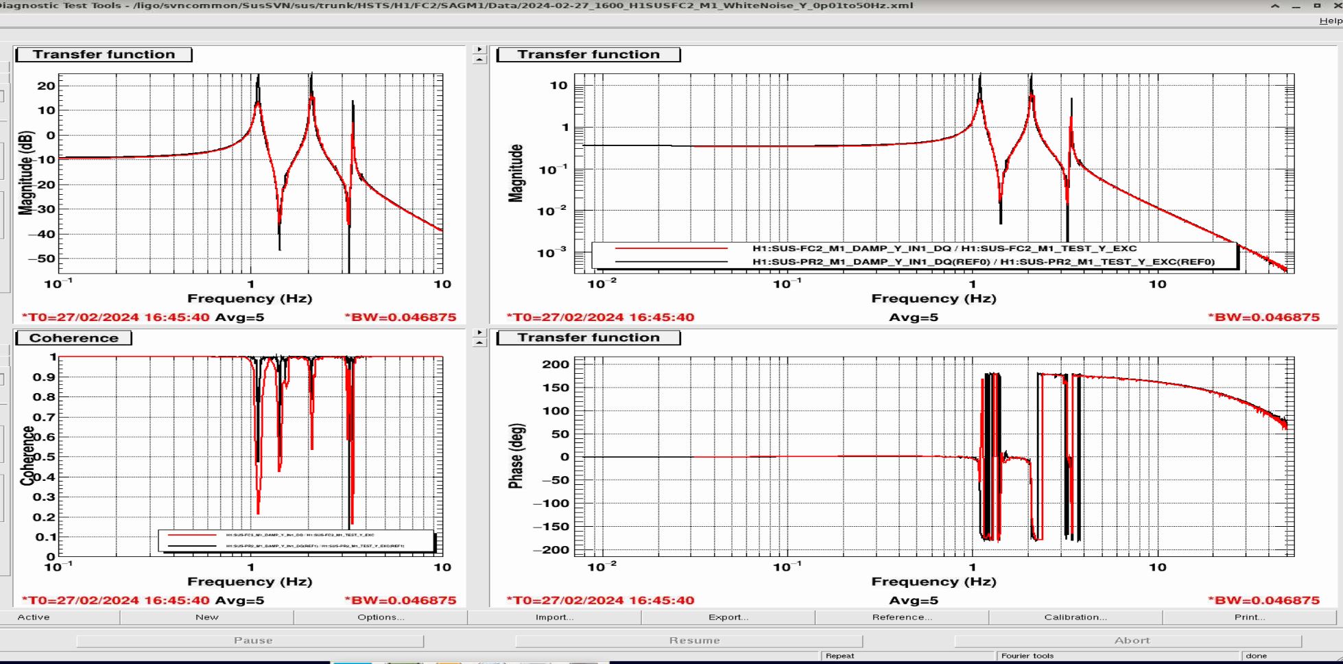
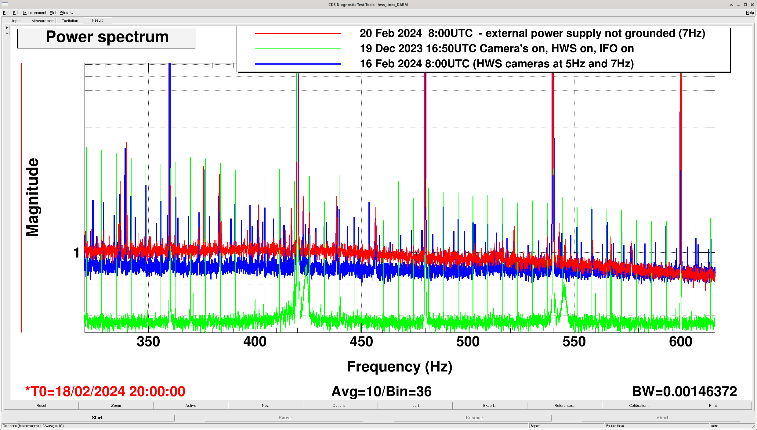
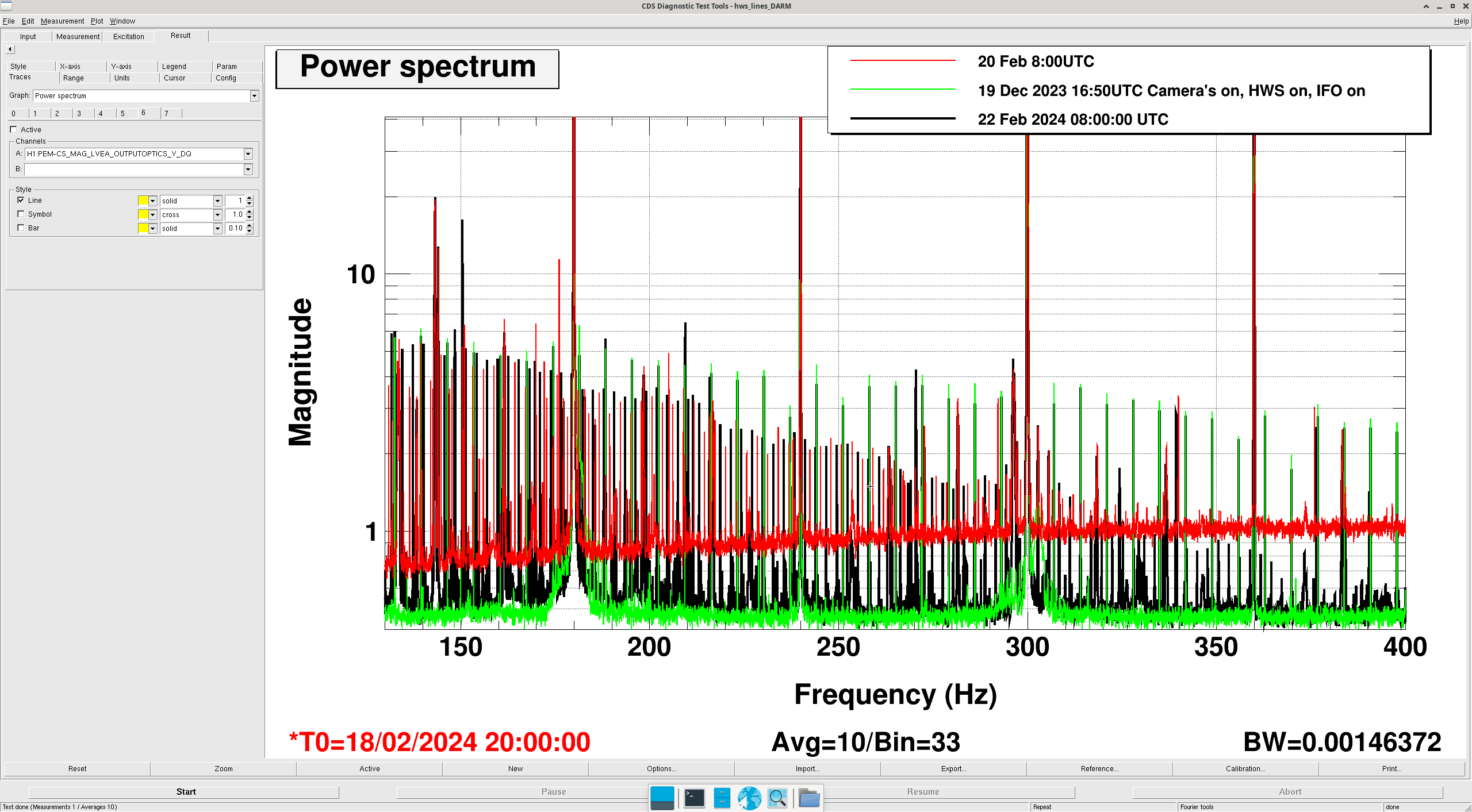
Attached are the results -- the magnitude of the transfer function -- for DCPD A and DCPD B. There are three traces: - The former measurement with the previous OMC DCPDs, on 2023 Jul 11. - The first measurement with the new OMC DCPDs connected, on 2024 Feb 22 (last week Thursday) - The second measurement with the new OMC DCPDs connected, on 2024 Feb 26 (yesterday, 4 days later) We do see some small change ([3.05e6 / 3.04e6 - 1]*100 = 0.3% reduction) in the magnitude below about 25 [Hz]. Preliminary investigations cover a few things that might cause this. Because of where the "wiggle of change" is happening at 25 [Hz] -- right at the RLC complex poles, I immediately suspect the environmental sensitivity of giant ~2.4 [Henry] inductors and/or the electrical grounding situation surrounding the TIA. Regarding the environmental situation: - The OMC and HAM6 are back mostly at ultra high vacuum (~1e-6 [Torr], when its typically 1e-7 [Torr]) :: (so, any physical distortions of the enclosure that would change the geometry of inductor should be similar) - The TIA has been powered on for several days even prior to the 2024 Feb 22 measurement :: (so the dominant thermal load on the circuit -- the bias voltage -- should have had time to thermalize), and - 
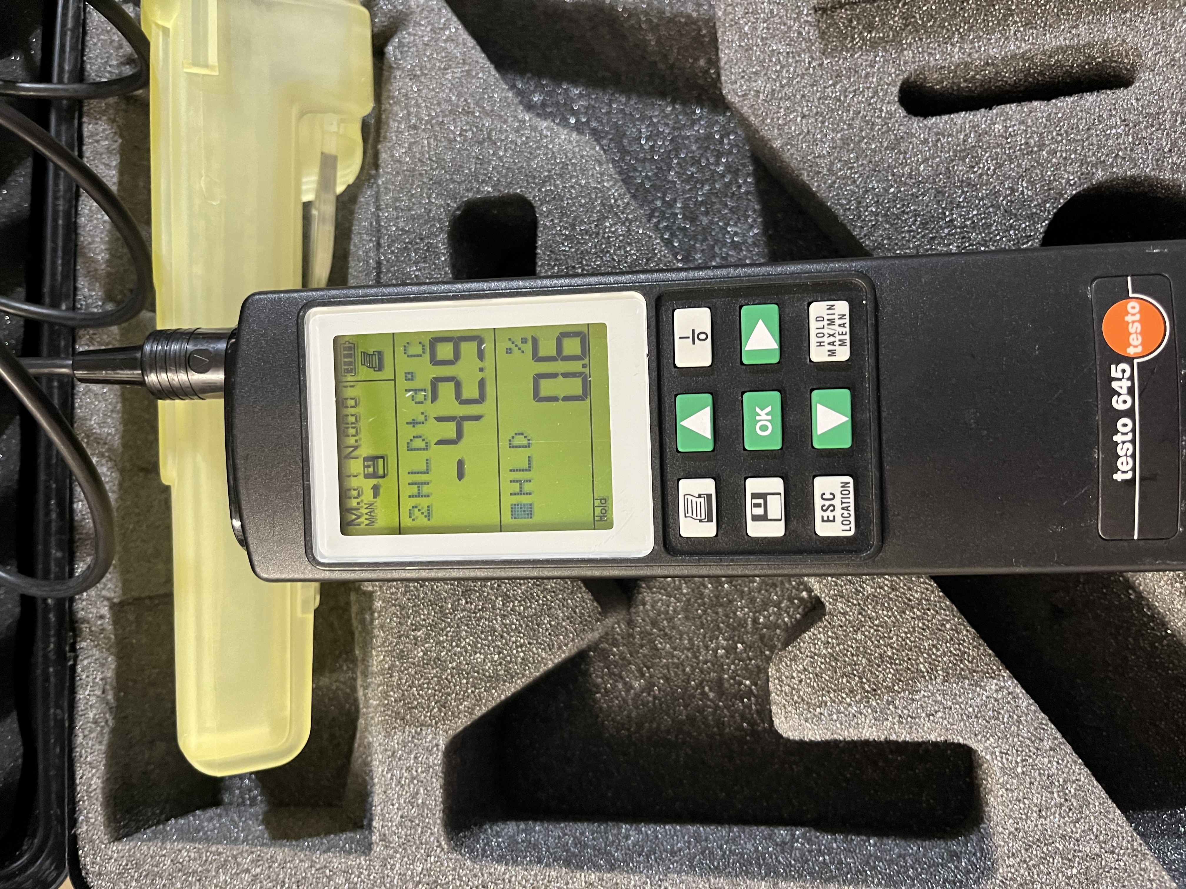
LVEA temperatures are stable, albiet 2 [deg C] cooler :: (I'm not sure if a 2 [deg C] in the external environment will have such an impact on the PDs) Of course, it's an odd coincidence that both DCPDs chain response changed in the same direction and magnitude -- maybe this is a clue. The fact that the 2024-Feb-22 and 2024-Feb-26 measurements agree indicate that: - The change is stable across a few days, implying that - The TIA circuit has been on for a while, and circuit is thermalized 
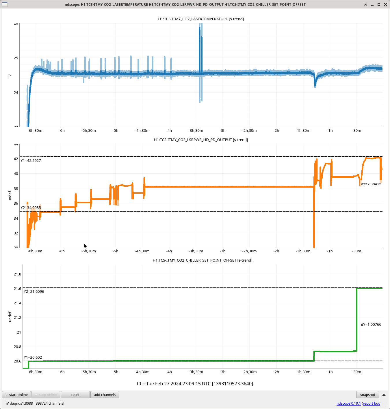
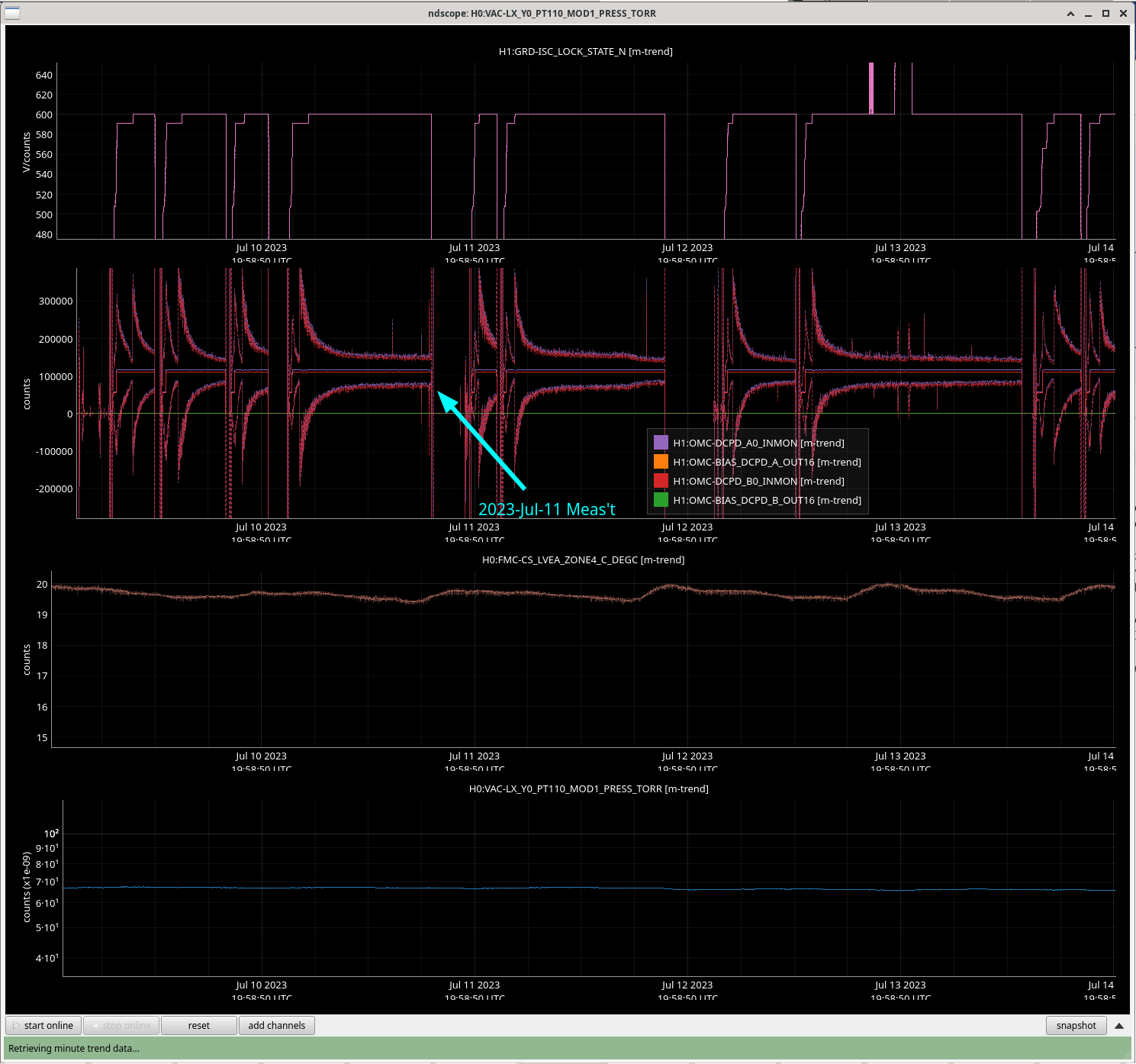
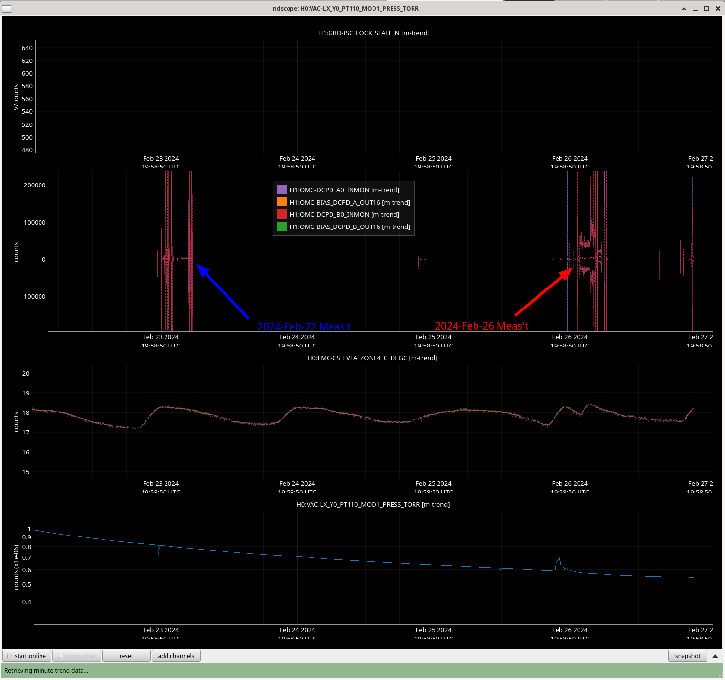
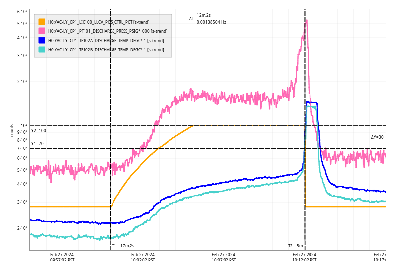
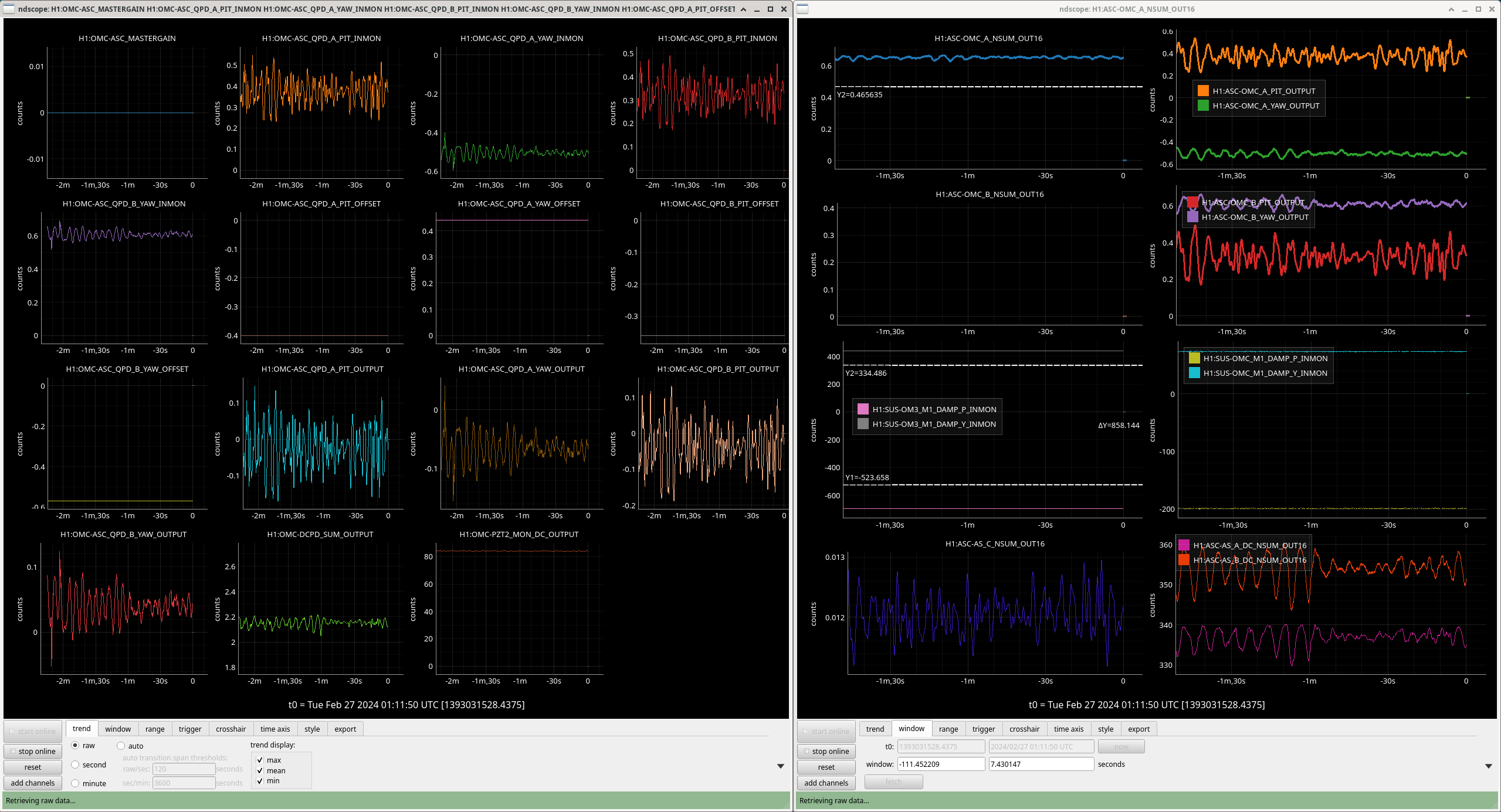
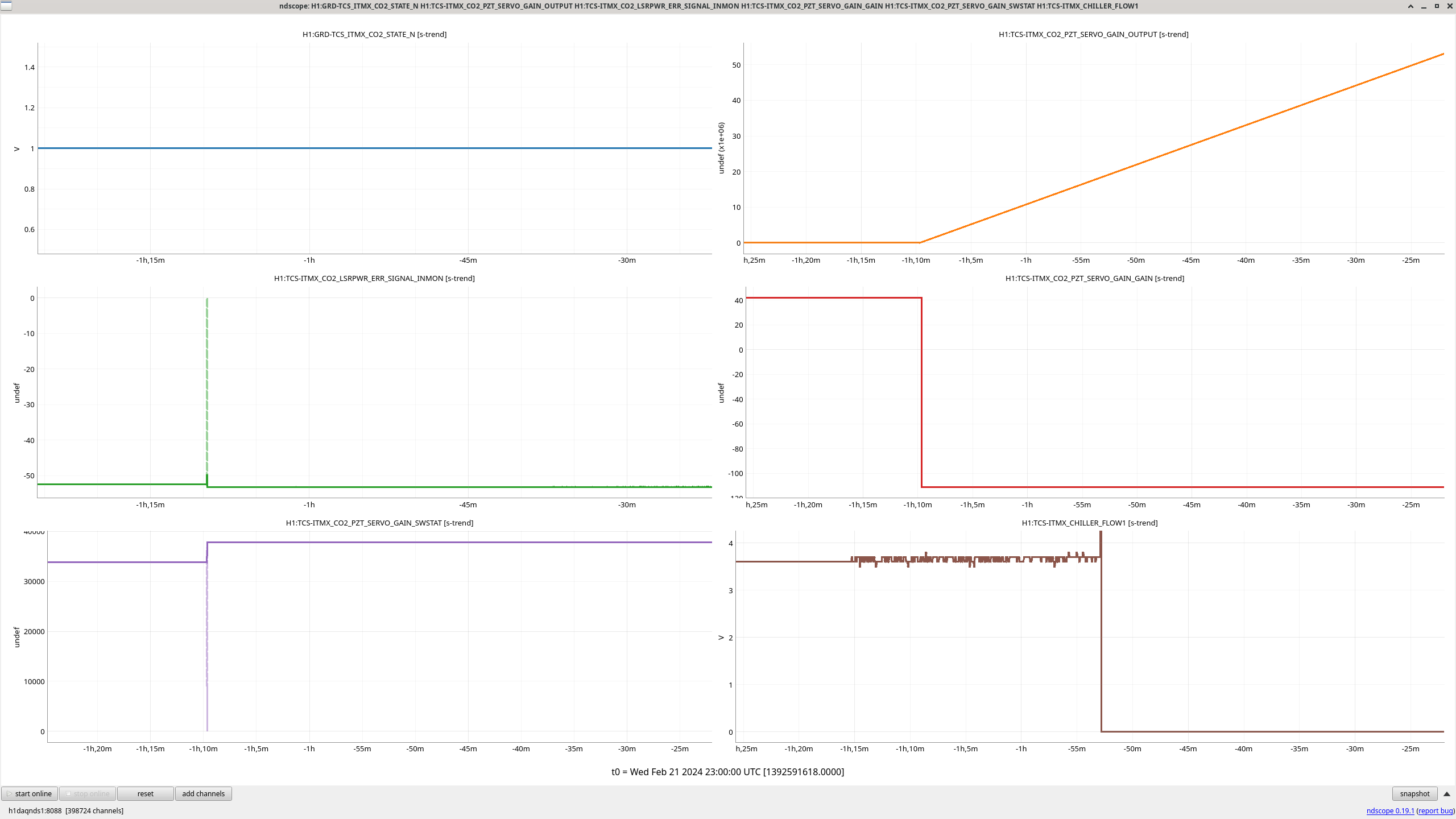
Also attached are trends of these environmental conditions during the 2023-Jul-11 and both 2024-Feb measurements. 
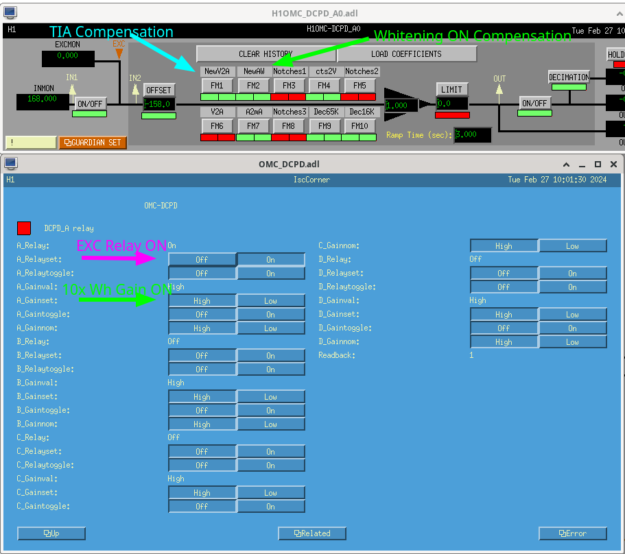
Also also attached are the two relevant MEDM screens showing the OMC DCPD A0 filter bank configuration during the DCPD A measurement (OMC DCPD B0 is the same), and the Beckhoff switch states for the excitation relay in the TIA and the whitening gain relay in the whitening chassis. %%%%% What's next? %%%%%% (1) Ask Keita / Koji / Ali some details about the DCPD chain that I've missed having been out. (a) Are you sure you plugged in the transmitted PD into DCPD A and the reflected PD into DCPD B, the configuration we'd had with the previous OMC? (b) When were the electronics powered on? (c) Can you confirm that other than the DCPDs and the cable connecting them to the TIA, no electronics have changed? (2) Using the same remote measurement, configure the system to measure the TIA response by itself to see if there's a change and if so if it matches this overall chain change. (3) If (2) doesn't work, use the remote measurement tool to measure the TIA and the Whitening together, take the ratio of (3)/(2) to see if the whitening chassis response has somehow changed. (4) If the answers to (1), (2), or (3) don't solve the mystery, or provide a path forward, then we ask "does this *matter*?" A reminder -- any change in the frequency dependence of the OMC DCPD GW path electronics that's not compensated is immediate and direct systematic error in the overall DARM calibration if not accounted for. So the question is does 0.3% error below 25Hz matter, or is it beneath the uncertainty on the systematic error in calibration that's present already for other reasons? To answer this question, we'll resurrect code from G2200551, LHO:67018, and LHO:67114 which creates an estimate of the impact on the calibration's *response* function systematic error, i.e. creating an "eta_R." (5) If the resulting estimate of eta_R is big compared with the rest of systematic error budget, then it matters, and we're left no other course of action than to out to the HAM6 ISC racks with our trusty SR785, remeasure the analog electronics from scratch, fit the data, and update the compensation filters a la LHO:68167.
Here's the debrief I received from Koji and Keita:
(a) Are you sure you plugged in the transmitted PD into DCPD A and the reflected PD into DCPD B, the configuration we'd had with the previous OMC?
Koji says ::
The now installed OMC is so-called Unit 1.
- 40m eLOG 18069 covers the PD installation
. The PD in transmission is B1-22
. The PD in reflection is B1-23
- PD datasheet vendor provided can be found in E1500474
- Test Results for the OMC and its PDs can be found in E1800372
(b) When were the electronics powered on?
Keita says "The TIA was only briefly powered down and disconnected from its in-air whitening chassis while I was checking for connection to electrical ground. Otherwise it has been powered on."
Given that doors were closed on 2024-Feb-07 (see LHO:75811 and LHO:75810), the TIA would have been powered on for at least 15 days prior to my first measurement on 2024-Feb-22.
So we can rule out that this discrepancy might have been because the electronics had not yet have been at thermal equilibrium.
(c) Can you confirm that other than the DCPDs and the cable connecting them to the TIA, no electronics have changed?
According to Appendix D of T1500060 (P180) the former, now de-installed, H1 OMC from Aug 4, 2016 (aka Unit 3) had the onboard cable twisted.
Comparing this with the past LLO unit (aka Unit 1, now installed to LHO), I expect that the role of DCPD A and B are now swapped from the previous OMC (Unit 3).
HAM8 ground loops checks completed. All passed. Some cables previously modified per E2100504. This was to resolve known in-chamber ground issues for FC2 Top (BOSEM).
Description Cable Location Notes
FC2 Top FC2_001 FCES SUS-C1 Pin 13 and shield lifted per E2100504
FC2 Top FC2_002 FCES SUS-C1 Pin 13 and shield lifted per E2100504
FC2 Middle FC2_003 FCES SUS-C1 Tested ok
FC2 Bottom FC2_004 FCES SUS-C1 Tested ok
Tue Feb 27 10:12:02 2024 INFO: Fill completed in 11min 57secs
Gerardo confirmed a good fill curbside.
Closes 26233, last done in 75700
Laser Status:
NPRO output power is 1.807W (nominal ~2W)
AMP1 output power is 67.22W (nominal ~70W)
AMP2 output power is 141.2W (nominal 135-140W)
NPRO watchdog is GREEN
AMP1 watchdog is GREEN
AMP2 watchdog is GREEN
PMC:
It has been locked 0 days, 0 hr 6 minutes
Reflected power = 16.3W
Transmitted power = 108.3W
PowerSum = 124.6W
FSS:
It has been locked for 0 days 0 hr and 0 min
TPD[V] = -0.01492V
ISS:
The diffracted power is around 3.3%
Last saturation event was 0 days 0 hours and 5 minutes ago
Possible Issues:
FSS TPD is low
ISS diffracted power is high
All looks nomial except for the PMC and FSS not being locked for a long duration of time, but this is expected with the ongoing in chamber PSL work.
Closes FAMIS 26487, last completed 75223
T240:
Averaging Mass Centering channels for 10 [sec] ...
2024-02-27 09:30:04.266757
There are 11 T240 proof masses out of range ( > 0.3 [V] )!
ITMX T240 1 DOF X/U = -1.057 [V]
ITMX T240 1 DOF Y/V = 0.379 [V]
ITMX T240 1 DOF Z/W = 0.496 [V]
ITMX T240 2 DOF Y/V = 0.319 [V]
ITMX T240 3 DOF X/U = -1.07 [V]
ITMY T240 3 DOF X/U = -0.485 [V]
ITMY T240 3 DOF Z/W = -1.448 [V]
BS T240 1 DOF Y/V = -0.33 [V]
BS T240 3 DOF Y/V = -0.31 [V]
BS T240 3 DOF Z/W = -0.421 [V]
HAM8 1 DOF Z/W = -0.408 [V]
All other proof masses are within range ( < 0.3 [V] ):
ETMX T240 1 DOF X/U = -0.03 [V]
ETMX T240 1 DOF Y/V = 0.005 [V]
ETMX T240 1 DOF Z/W = -0.022 [V]
ETMX T240 2 DOF X/U = -0.135 [V]
ETMX T240 2 DOF Y/V = -0.123 [V]
ETMX T240 2 DOF Z/W = -0.089 [V]
ETMX T240 3 DOF X/U = 0.022 [V]
ETMX T240 3 DOF Y/V = -0.096 [V]
ETMX T240 3 DOF Z/W = 0.026 [V]
ETMY T240 1 DOF X/U = 0.15 [V]
ETMY T240 1 DOF Y/V = 0.173 [V]
ETMY T240 1 DOF Z/W = 0.233 [V]
ETMY T240 2 DOF X/U = -0.025 [V]
ETMY T240 2 DOF Y/V = 0.21 [V]
ETMY T240 2 DOF Z/W = 0.128 [V]
ETMY T240 3 DOF X/U = 0.257 [V]
ETMY T240 3 DOF Y/V = 0.186 [V]
ETMY T240 3 DOF Z/W = 0.184 [V]
ITMX T240 2 DOF X/U = 0.189 [V]
ITMX T240 2 DOF Z/W = 0.295 [V]
ITMX T240 3 DOF Y/V = 0.193 [V]
ITMX T240 3 DOF Z/W = 0.166 [V]
ITMY T240 1 DOF X/U = 0.093 [V]
ITMY T240 1 DOF Y/V = 0.108 [V]
ITMY T240 1 DOF Z/W = 0.031 [V]
ITMY T240 2 DOF X/U = 0.082 [V]
ITMY T240 2 DOF Y/V = 0.254 [V]
ITMY T240 2 DOF Z/W = 0.09 [V]
ITMY T240 3 DOF Y/V = 0.06 [V]
BS T240 1 DOF X/U = -0.161 [V]
BS T240 1 DOF Z/W = 0.14 [V]
BS T240 2 DOF X/U = -0.038 [V]
BS T240 2 DOF Y/V = 0.061 [V]
BS T240 2 DOF Z/W = -0.11 [V]
BS T240 3 DOF X/U = -0.144 [V]
HAM8 1 DOF X/U = -0.16 [V]
HAM8 1 DOF Y/V = -0.087 [V]
Assessment complete.
STS:
Averaging Mass Centering channels for 10 [sec] ...
2024-02-27 09:31:21.264093
There are 2 STS proof masses out of range ( > 2.0 [V] )!
STS EY DOF X/U = -4.12 [V]
STS EY DOF Z/W = 2.85 [V]
All other proof masses are within range ( < 2.0 [V] ):
STS A DOF X/U = -0.505 [V]
STS A DOF Y/V = -0.796 [V]
STS A DOF Z/W = -0.601 [V]
STS B DOF X/U = 0.433 [V]
STS B DOF Y/V = 0.971 [V]
STS B DOF Z/W = -0.463 [V]
STS C DOF X/U = -0.698 [V]
STS C DOF Y/V = 0.84 [V]
STS C DOF Z/W = 0.431 [V]
STS EX DOF X/U = -0.106 [V]
STS EX DOF Y/V = 0.07 [V]
STS EX DOF Z/W = 0.038 [V]
STS EY DOF Y/V = 0.156 [V]
STS FC DOF X/U = 0.483 [V]
STS FC DOF Y/V = -0.699 [V]
STS FC DOF Z/W = 0.869 [V]
Assessment complete.
Transfer function results for FC2 in HAM8 shows that the suspension is healthy, hence we are ready to close the door of this chamber. Results for all six dof are attached below.
TITLE: 02/27 Day Shift: 16:00-00:00 UTC (08:00-16:00 PST), all times posted in UTC
STATE of H1: Planned Engineering
OUTGOING OPERATOR: None
CURRENT ENVIRONMENT:
SEI_ENV state: CALM
Wind: 5mph Gusts, 3mph 5min avg
Primary useism: 0.02 μm/s
Secondary useism: 0.34 μm/s
QUICK SUMMARY:
LVEA is still in LASER HAZARD
CDS Looks good
Temperatures in the LVEA Zone 4 look to be leveling out well at 67C
Today's Expected work:
HAM8 finish work and close up
More Vacuum Leak Checks and RGA scans
Possibly some OPLEV work.
Workstations were updated and rebooted. OS packages were updated.
cdsutils was updated in conda to 1.7.0 on cdsws22 and cdsws27. It can be activated on any other workstation by running 'conda activate cds-testing'
Today's activities: - The corner (BSC8 blanks and 1000 amu RGA GV) was leak checked, and everything was found OK - this is a big relief, as this was not anticipated - see https://alog.ligo-wa.caltech.edu/aLOG/index.php?callRep=75717 - After this, the Kobelco is now shut off: https://alog.ligo-wa.caltech.edu/aLOG/index.php?callRep=75980 - HAM7 pumpdown status: ~5.9E-7 Torr - Corner pumpdown: ~4.4E-7 Torr, ~147 hours after the HV pumping started - EX pumpdown status: 2.6E-8 Torr. The GV will remain closed during FAC works (during this week) - At the EX RGA the bakeout temperature has been ramped up to 200 deg C - There was an issue with the RGA connections, which has been resolved in the afternoon. Tomorrow RGA scans and possibly bakeouts will be done at the HAM7 and the OMC RGAs - A pumping cart was connected to the GV2 annulus system, and its all-metal valve has been opened. Now it is being pumped with the cart in parallel with the AIP - The relay tube was valved in to HAM7 (RV2 is open now)
The purge air system (Kobelco unit) was turned off this morning around 18.20 utc. Took a dew point reading of the air at the dryer and got -42.9 degrees C. The system was inspected daily at least once since it was turned on to support the current vent, current run hours 10,965.9. No leaks were noted on the compressor.
However, one valve for the Pneumatech left drying tower needs to be replaced, this is a small actuated purge valve leaking dry processed air, leak is at the stem. FRS ticket filed 30556.
Dhruva, Nutsinee, Naoki
We aligned the pump AOM and fiber. The pump fiber coupling is 43%. We also optimized the seed fiber polarization. We have ~50% of seed throughput from fiber to SQZT7.
First we aligned the pump AOM. We set the pump ISS drivepoint at 0V and aligned the AOM to maximize the AOM throughput. The AOM throughput was 62% before alignment and is 90% after alignment. Then we set the pump ISS drivepoint at 5V and aligned the AOM to maximize the +1st order beam. After we aligned the pump fiber, the pump before fiber is 21.6mW, the pump OPO REFL is 3.05mW, and the pump OPO REFL rejected is 1.55mW with OPO unlocked. Given the 50:50 BS for SK path, the pump fiber coupling should be (3.05+1.55)*2/21.6 = 43%.
In 75951, we found that the seed launch power increases when the seed shutter is open. Today we found that it is due to the backscattered seed from the seed fiber coupler. We blocked the backscattered seed and now the seed launch power doesn't change with the seed shutter.
Today we managed to realign the cameras on HAM6 which show OMC TRANS and AS AIR. At first we could not see any response from the AS AIR camera so there were some cable swapping back and forth, reseating of cables and a few reboots by Dave B/control room. At some point it started working again.
In any case, beams are now on these cameras.
Vicky, Jennie, Swadha,
After the camera was aligned we realised the 1mA mode Vicky and I were locking the OMC to on Friday was a 1/0 mode. This explains why we were having problems getting the yaw ASC on the OMC to converge as the cavity alignment was off in yaw.
We then scanned the PZT2 until we saw TM00 on the camera and could see error signals on the input to the LSC servo then tweaked the OM1 and OM Sus alignment until the mode height was maximised at 2mA.
We were not sure if ASC was working - even with a nice TM00 mode and all the offsets on the QPDs altered so the outputs of each ASC_QPD_{A,B}_{PIT,YAW}_{OUTPUT} were 0. We also tried gain flips and we found a stable situation for ASC, but didn't check if it was really locked. The stable situation (ASC not railing) was sign flips on both yaw gains for the OMC-ASC_{POS,ANG}_X_GAIN and OMC-ASC_{ANG}_Y_GAIN. We reverted the changes we made except for OMC-ASC_{POS,ANG}_X_GAIN.
Attached is a nice lock stretch as an example of how good a mode we could get after Swadha tried to tweak up the alignment of OMC and OM3 (the nominal for earlier mode scans was a locked level of 3mA on the DCPD_SUM_OUPUT).
Below are the reference values for calculating the loss
Locked 1.3659 mW at 1:29:18 UTC for OMC_REFL_A_LF_OUTPUT
Unlocked at 4.25555 mW 1:40:47 UTC for OMC_REFL_A_LF_OUTPUT
2.16955 mA at 1:30:07 UTC for same lock stretch on DCPD_SUM_OUTPUT
(REFL channels are noted as calibrated in mW on OMC.adl screen, think DCPD_SUM is calibrated in mA).
Scan starts 2:05:27 UTC 200s. Using tamplate Feb26_2024_PSL_OMC_scan_coldOM2.xml in /userapps/sqz/h1/Templates/dtt/OMC_SCANS
Second image is the scan we took.
Screenshot of OMC LSC locking and relevant signals attached. The OMC LSC capture range is quite small, so likely last week we were trying to lock LSC while not being in range of the LSC error signal. Scanning OMC PZT2 in step sizes of 0.1, looking for the LSC_I error signal into the OMC LSC servo, then locking the LSC servo loop, worked.
Just to clarify scan started at 2:05:27 UTC on 2024-02-27 and template runs two 100s scans up in voltage.
With the CDS and Beckhoff work yesterday some large numbers got into the CHILLER_SET_POINT filters which requested a low setpoint for CO2X, the laser faulted and turned of when it got to 15degC at 22:06UTC yesterday. This morning I turned it back on and set H1:TCS-ITMY_CO2_CHILLER_SERVO_GAIN_GAIN from 1 to 0 (as in alog 75715) to stop any feedback form the laser being off gong to the chiller).
TJ and I plan to make sure the H1:TCS-ITMX_CO2_PZT_SERVO_GAIN_SW2R is correctly turned on and off in the Guardian code when the CO2 lasers are taken DOWN to avoid this in future.
This is correctly turned off in DOWN but the Beckhoff work on this day changed the settings (plot) and we did not rerun the DOWN state. TJ has added a detector to TCS_ITM{X,Y}_CO2 guardians to rerun DOWN state if H1:TCS-ITMX_CO2_PZT_SERVO_GAIN_OUTPUT goes >1000. Usually below 100 but has an intergrator that can act strangely on Beckhoff channel changes. Tested and loaded in both X and Y.
Fil, Luis, Camilla. FRS 26828#c11 Previous troubleshooting in alog 74951, 74750.
Today Fil went onto the HWS table and verified the HWS cameras are connected straight to the external power supply (photos in FRS26828#c8) via cables connected together. The HWS camera fiber CLink box is powered by the HWS breakout chassis D1200934 (originally designed to power cameras too).
Fil theorized that the HWS grounding is due to the power supply to fiber CLink connection grounding the cameras! With a multi-meter, we verified the HWS camera is grounded to the table when the CLink power cable is connected but when we disconnect CLink power, the camera is not grounded to the table (has Kapton tape and plastic bolts).
Step 1 (Completed): I removed the grounding cables from the HWS external power supply as Luis suggested in FRS 26828#c11, to avoid us holding the cameras negative terminal at mains ground. Photo of current connections attached.
Step 2 (Planned): After verifying step 1 doesn't effect the combs (need overnight "quiet" data), Fil will make a new cable to power both the camera and CLink's via the external supply (14V is fine for both).
Preet, Camilla
It appears changing the cabling of the external power supply has removed/reduced the comb: compare blue trace before cabling change to red trace afterwards change in attached plot.
To verify this, we undid the cabling change, back to the old configuration this morning at 9:30am and turned the camera back to 7Hz each, we'll later check if the comb reappears.
Preet, Camilla, FRS 26828
With the swap back to the old cabling, we confirmed that the comb came back, see Feb 22nd data in attached plot. This morning I changed the cabling back to the "quiet" version, photo attached.
Question for others, is the old cabling expected to push noise into DARM or is there an unknown coupling? Tagging PEM, CDS, Detchar.
Have you try using a different power supply or low the voltage to +12v? the camera also works with +12v and the rcx c-link only required +5v supply.
Rick and I cleaned the optics out here at End X.
Noted a drop in MAX Diffracted Power between M5 and the Wedged Beam Splitter from 1.1W to 1.08 W.
This may be due to the laser being turned off and not thermalized.
We would like to come back to End X and adjust the AOM alignment and we are leaving PCAL in a LASER SAFE status, LASER OFF and Key out.
The results of our TX module maintenance is recorded on the DCC spreadsheet: T2400029
https://dcc.ligo.org/LIGO-T2400029