david.barker@LIGO.ORG - posted 10:14, Sunday 25 February 2024 (75957)
Sun CP1 Fill
Sun Feb 25 10:09:42 2024 INFO: Fill completed in 9min 38secs
Images attached to this report
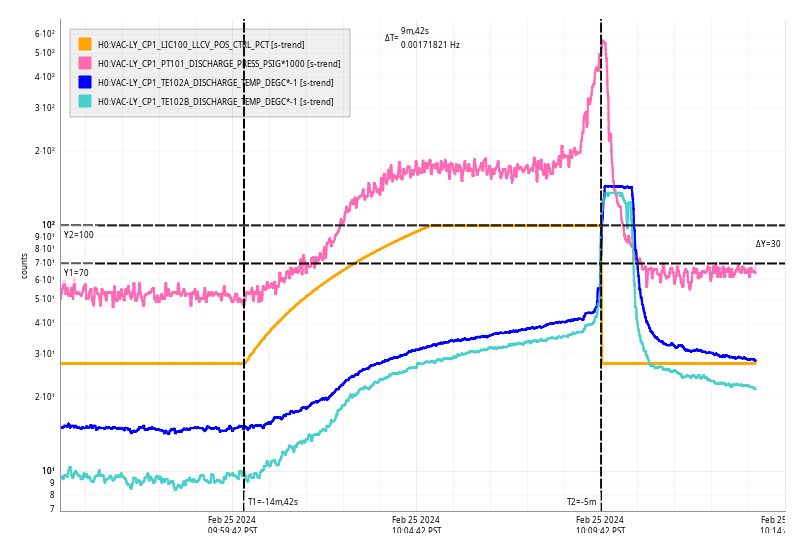
Sun Feb 25 10:09:42 2024 INFO: Fill completed in 9min 38secs
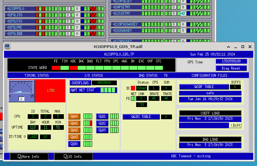
At 04:26:10 Sun 25 Feb 2024 PST all the models on h1psl0 crashed.
lspci shows we have lost an ADC card, only 3 are visible on the bus.
dmesg output:
[Wed Feb 21 12:08:41 2024] nfs: server 10.101.0.17 OK
[Sun Feb 25 04:27:11 2024] rts_cpu_isolator: LIGO code is done, calling regular shutdown code
[Sun Feb 25 04:27:11 2024] h1ioppsl0: ERROR - An ADC timeout error has been detected, waiting for an exit signal.
[Sun Feb 25 04:27:11 2024] h1psldbb: ERROR - An ADC timeout error has been detected, waiting for an exit signal.
[Sun Feb 25 04:27:11 2024] h1pslfss: ERROR - An ADC timeout error has been detected, waiting for an exit signal.
[Sun Feb 25 04:27:11 2024] h1pslpmc: ERROR - An ADC timeout error has been detected, waiting for an exit signal.
[Sun Feb 25 04:27:11 2024] h1psliss: ERROR - An ADC timeout error has been detected, waiting for an exit signal.
(diskless)root@h1psl0:/home/controls#
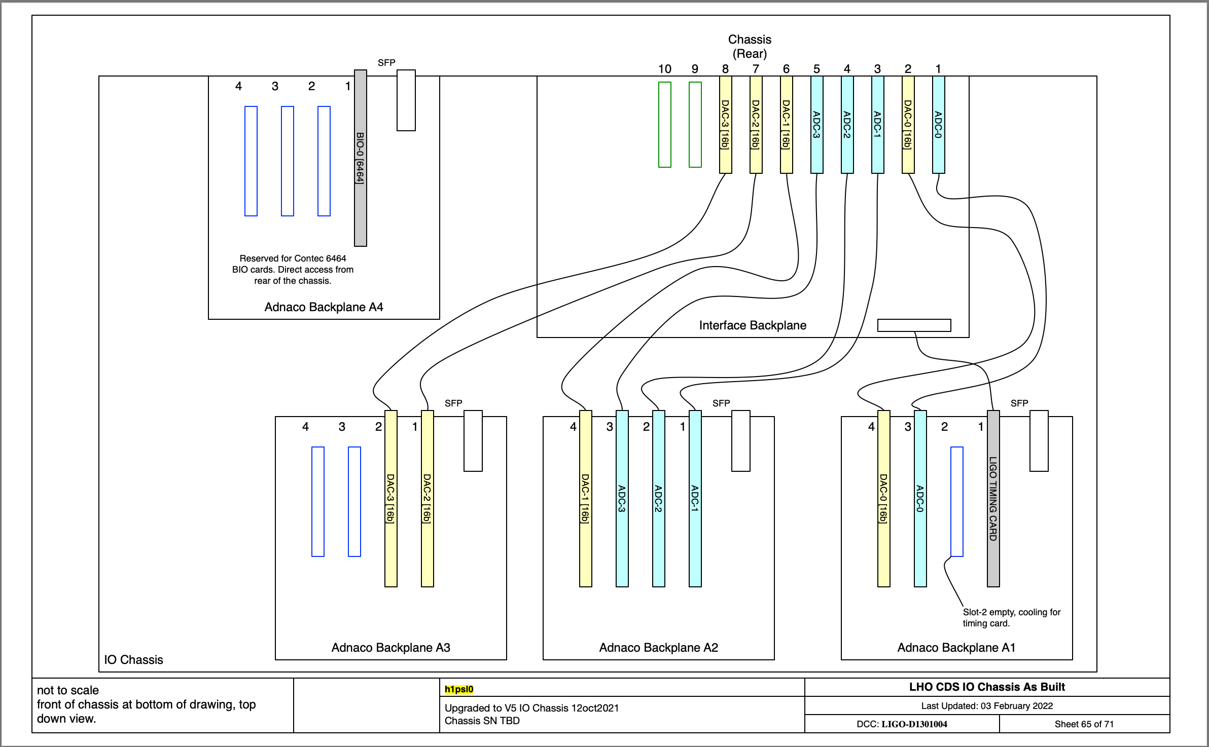
4th ADC (adc-3) card is missing
ADC cards: 6d, 75, 78
16bitDAC cards: 6f, 7c, b8, bb
lspci -nvt listing:
-+-[0000:b2]-+-00.0-[b3-bd]----00.0-[b4-bd]----01.0-[b5-bd]----00.0-[b6-bd]--+-01.0-[b7-b8]----00.0-[b8]----04.0 10b5:9056 <<< DAC dac-2
| | +-04.0-[b9]--
| | +-05.0-[ba-bb]----00.0-[bb]----04.0 10b5:9056 <<< DAC dac-3
| | +-07.0-[bc]-- <<< Empty slot
| | \-09.0-[bd]-- <<< Empty slot
| +-02.0-[be-c7]----00.0-[bf-c7]----01.0-[c0-c7]----00.0-[c1-c7]--+-01.0-[c2-c3]----00.0-[c3]----00.0 1221:8682 <<< Contec BIO6464
| | +-04.0-[c4]--
| | +-05.0-[c5]--
| | +-07.0-[c6]--
| | \-09.0-[c7]--
.
+-[0000:64]-+-00.0-[65-6f]----00.0-[66-6f]----01.0-[67-6f]----00.0-[68-6f]--+-01.0-[69]----00.0 10ee:d8c6 <<< LIGO Timing Card
| | +-04.0-[6a]--
| | +-05.0-[6b]-- <<< Empty Slot (cooling for TC and cable run)
| | +-07.0-[6c-6d]----00.0-[6d]----04.0 10b5:9056 <<< ADC adc-0
| | \-09.0-[6e-6f]----00.0-[6f]----04.0 10b5:9056 <<< DAC dac-0
| +-02.0-[70-7c]----00.0-[71-7c]----01.0-[72-7c]----00.0-[73-7c]--+-01.0-[74-75]----00.0-[75]----04.0 10b5:9056 <<< ADC adc-1
| | +-04.0-[76]--
| | +-05.0-[77-78]----00.0-[78]----04.0 10b5:9056 <<< ADC adc-2
| | +-07.0-[79-7a]--+-[0000:7a]---04.0 10b5:9056 <<< Corrupted address, should be ADC adc-3
| | | \-[0000:79]---00.0 10b5:8111
| | \-09.0-[7b-7c]----00.0-[7c]----04.0 10b5:9056 <<< DAC dac-1
| +-05.0 8086:2034
IO Chassis Layout:
10:29 PST: I power cycled h1psl0. As expected this did not fix the issue, and now the lspci scan is not reporting anything in the ADC-3 slot, with DAC-1's address changing from 7c to 7b.
Adnaco second BackPlane is now:
| +-02.0-[70-7b]----00.0-[71-7b]----01.0-[72-7b]----00.0-[73-7b]--+-01.0-[74-75]----00.0-[75]----04.0 10b5:9056 <<< ADC adc-1
| | +-04.0-[76]--
| | +-05.0-[77-78]----00.0-[78]----04.0 10b5:9056 <<< ADC adc-2
| | +-07.0-[79]-- <<< MISSING ADC adc-3
| | \-09.0-[7a-7b]----00.0-[7b]----04.0 10b5:9056 <<< DAC dac-1
I. Abouelfettouh, J. Kissel, O. Patane, B. Weaver
Executive Summary: The first article BBSS transfer functions look great. Though there is some confusion about the M1 P 2 P modeled transfer functions drastically disagreeing with the measured TFs, there is a consistent story between
- the adjustments to the mechanics that were made during construction and
- deviations from the "production" model parameter set that could re-create those construction adjustments.
Further discussion will be had with the assembly / design team as to the future course of action.
Kissel suggests that -- even as the first article stands now -- the resulting measured transfer functions with the mechanical adjustments would/should happily meet A+ O5 requirements.
%%%%%%%%%%% Begin kLOG (You missed these...) %%%%%%%%%%%%%%
I got a debrief yesterday from Betsy, Oli, and Ibrahim of the comparison between
- measured transfer function results from the first article construction and
- what had been deemed the production model parameter set for the BBSS,
i.e. what's discussed in LHO:75787.
The existing "production" model parameter set starts from Mark's update to the BBSS parameter set post-final-design after adjusting for the production wire thicknesses (see TripleLite2_mark.barton_20211212bbss_production_triplep.m, changed at rev 11625, circa Sep 2023). Oli successfully copied over to the usual matlab formating to create bbssopt.m (created at rev 11734, circa Jan 2024).
At the start of the debrief, there were (only!!) 3 outstanding issues / questions they had:
(1) The overall magnitude scale for all DOFS for all measured transfer functions was a consistent factor of ~3.15x more than the model estimates,
(2) After browsing through the EULER-basis drive to OSEM-basis response plots, and some of the off-diagonal EULER-basis showed little-to-no coherence, and
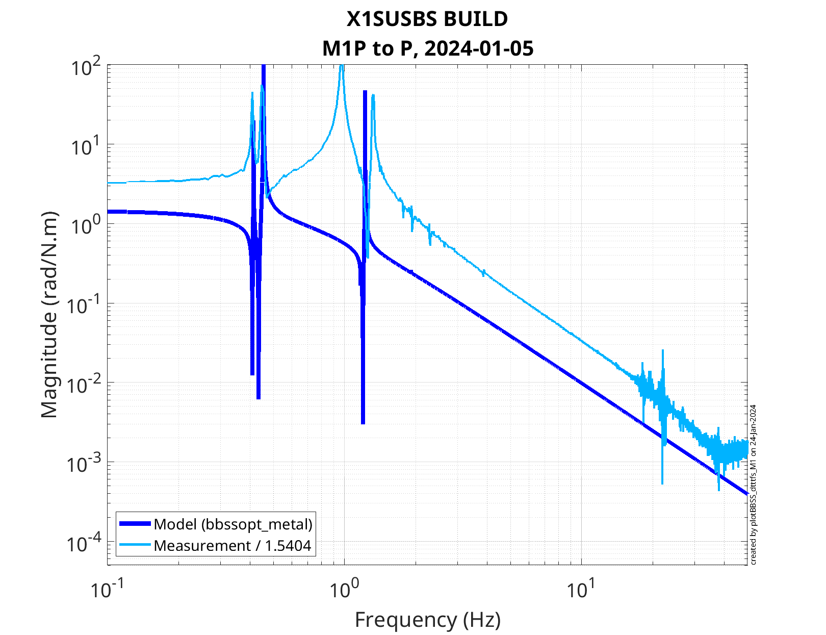
(3) The measured M1 Pitch to Pitch transfer function's frequency response was significantly different than the model.
For (1), this is typically a sign of a mis-calibration of the data. We reviewed the calibration of the measured data from the processing script, plotBBSS_dtttfs_M1.m, created by Oli and Ibrahim in Nov 2023. The DTT templates that measure the transfer function use the pre-calibrated output of the sensors for response channels i.e. the channels come in units of microns and microradians, so they only need a factor of 1e-6 [meters / micrometers]. The only substantial thing that needs calibrated into physical units during post-processing is the excitation. The review of the calibration of the exciation revealed nothing suspicious in the script based on our current expected knowledge of chain
- the test stand electronics (an 18-bit DAC = 20 / 2^18 [V/ct]),
- BBSS coil driver (a TTOP coil driver, coupled with a BOSEM coil = 11.9 [mA/V]),
- 10x10 magnet strength (1.694 [N/A]).
- (lever arms and numbers of actuators are pre-calibrated out via the EUL2OSEM matrix, generated by make_susbbss_projections..m, and installed in EPICs)
The above factors result in an overall calibration of 1 / 1.5405 [(m/N) / (um/DAC ct) or (rad/N.m) / [urad/DAC ct]] that's displayed in the legend of each of the plots from LHO:75787.
In the end, we were more interested in understanding (2) and (3) rather than getting to the bottom of the calibration. Further, the test stand is some old, pre-aLIGO concoction whose records and modifications are unclear. So we figure we just move on, accepting that we need to fudge the data by the extra factor of 3.15x. We'll get serious about figuring it out if there's still such a discrepancy after moving the BBSS over to the production H1 system.
For (2), all concerns can we waived off with expectations.
(a) The first plot of concern was the P to F1F2F3 plot (page 17 of 2024-01-05_1000_X1SUSBS_M1_ALL_TFs.pdf), in that the magnitude of the F2 and F3 TFs were low and/or noisy. This is expected because F2 and F3 OSEMs are along the (center of mass / axis of pitch rotation) of the BBSS's top mass. So they see no pitch by construction (for better or worse).
(b) The second collection of plots of concern were the off-diagonal DOFs,
(i) showing noise and/or
(ii) the opposite -- showing well-resolved cross-coupling in DOFs that we *don't* want cross-coupled.
We shouldn't be mad about (i) -- e.g. page 7 showing incoherence between L response to V drive and V response to L drive. What power is resolved in those transfer functions -- typically on/around resonances -- is because the TFs were taken undamped an in air. So there's just a ton of movement that an FFT might / cross-correlation might *think* is coherent with the drive, but it's really not.
We looked closer at any of the off-diagonal TFs that *were* resolved, (ii) -- e.g. page 9 showing well-resolved cross-coupling between R response to V drive and V response to R drive. In each of these TFs, we found that the magnitude of the cross-coupling, off-diagonal TF was less, if-not-MUCH less that the on-diagonal TF, which is good. Where it was close, it sort-of "is what it is." Little attention has been typically paid to mitigating the off-diagonal transfer functions during the design phase of LIGO suspensions to-date. Further, they often are a result of the unique construction of each individual instantiation of the suspension type. There's no much we can do about it post construction, and what we *do* do if it proves problematic to the detector, is dance around the problem with fancy controls techniques if needed.
For (3), we arrive at the meat of this aLOG :: The *model* of the M1 Pitch to Pitch transfer function looked very weird to me. Betsy mentions the during the construction of the first article they
(a) found a discrepancy between the fastener model vs. measured mass budget that resulted in an unclear relationship between the center of mass of each stage and their suspension points (typically called the "d" parameters)
(b) acknowledged there would be uncertainty in the location of the suspension point for the bottom mass / dummy optic given the wire-loop + optic prism system since the final distances between masses have not been measured.
This, coupled with the fact that no *other* DOFs disagreed with the model besides P to P, led me to suspect the model parameters that only impact the pitch dynamics may be incorrect:
(i) each stages' separation between suspension point and center of mass, the "d" parameters, and
(ii) the pitch moments of inertia.
For a reminder of the physical meaning of all of the triple suspension parameters, see T040072.
As such, using the bbssopt.m "production" or "Final Design" (FD) parameter set as starting point, we tweaked these parameters by 10%-ish or factors of 2 to gather intuition of of how it would impact the response of the P to P transfer function. As a result, we have come to the conclusion that, in order to explain the data, we need to
- increase "d1" by + 5 [mm]. This is the separation between the top (M1) mass center of mass and it's M1 to to M2 blade tip heights. In the absolute sense, this is increasing the "physical" d1 from -0.5 [mm] to +4.5 [mm], and
- increase "d4" by 1.5 [mm]. This is the separation between the bottom (M3) mass / dummy optic center of mass and the wire/prism break-off point. In the absolute sense, this is increasing the "physical" d4 from +2.6 [mm] to +4.1 [mm].
Check out the attached plots which demonstrate this.
Citing discussion of overall scale (1) from above, all *measured* transfer functions have been scaled to the model by a factor of (1 / 3.15). This just makes comparing model to measured frequency response a lot more clear.
First attachment :: comparison between the final design model parameters and a variety of reasonable deviations of d1 between *decreased* by 2.5 [mm] and *increased by 5 [mm]. You'll notice that once d1 surpasses +1.0 [mm], the transfer function starts to look more like a standard triple suspension's transfer funtion. a d1 of FD + 5.0 [mm] lines up well with the upper two resonances of the measured data, but reduces the frequency of the lowest two L and P modes to below the data.
Second attachment :: comparison between the final design model parameters and a variety of reasonable deviations of d4. You'll notice that d4 really only have an impact on the lowest two L and P modes.
Third attachment :: comparison between the final design model parameters and a variety of reasonable deviations of the top (M1) mass' moment of inertia, the I1y parameter.
Fourth attachment :: comparison between the final design model parameters and a variety of reasonable deviations of the middle (M2) mass' moment of inertia, the I2y parameter.
Fifth attachment :: comparison between the final design model parameters and a variety of reasonable deviations of the bottom (M3) mass' moment of inertia, the I3y parameter.
None of the modeled changes to the moment of inertia -- shown in the third, fourth, and fifth attachments -- show promise in reproducing the measured results.
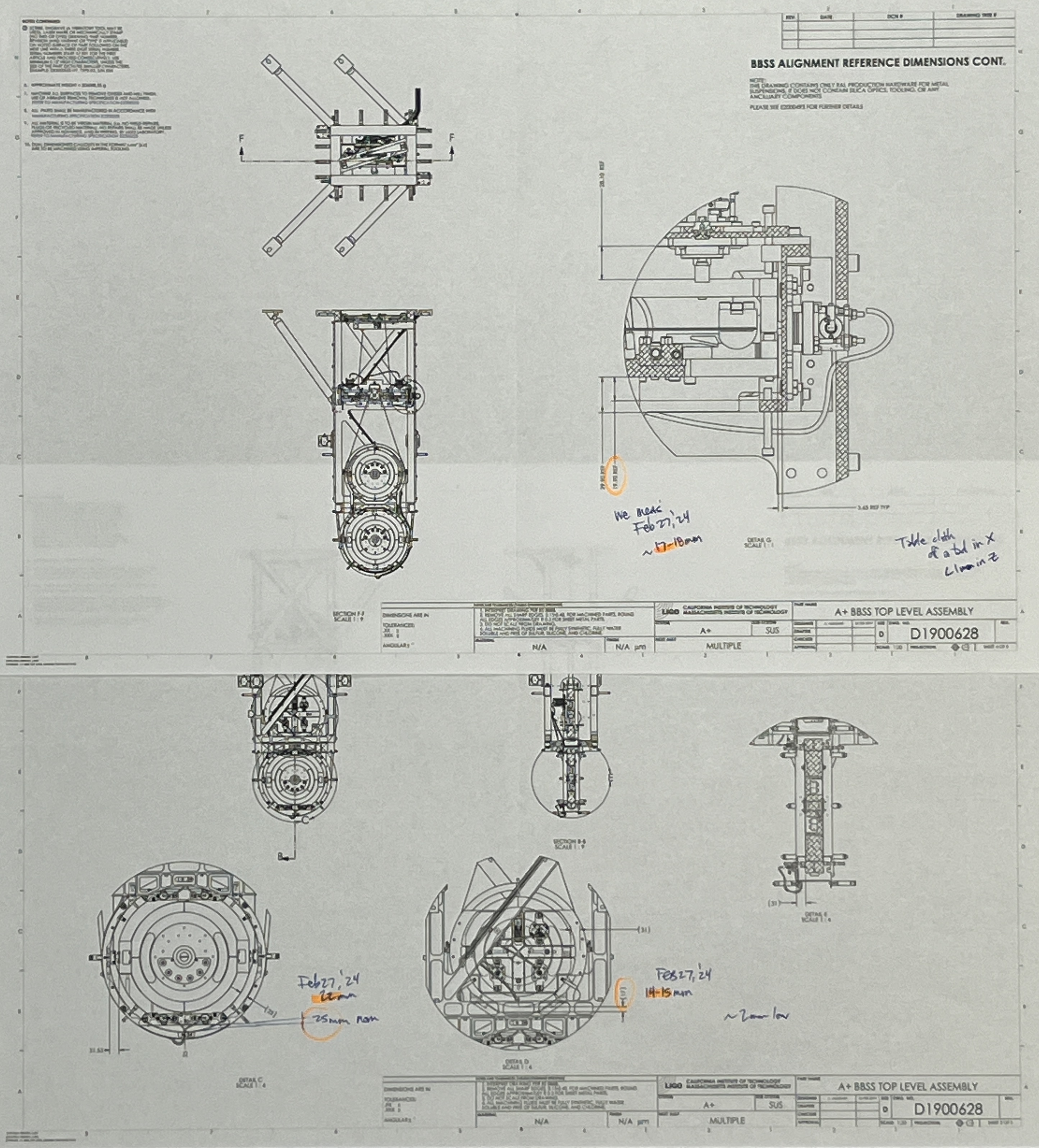
Sixth and Final attachment :: comparison between the final design model parameters and one with only d1 increased by +5 [mm], and d4 increased by +1.5 [mm].
The modified model in this last attachment fits the data the best, so we conclude that the issues with mechanical construction (3a) and (3b) are consistent with the measured data :: the reconfigured mass budget needed from fastener issues resulted in a deviation from design value for d1, and the imprecision of the mass-to-mass distances and wire-loop / prism system resulted in a roughly ~2 [mm] slop for this assembly.
%%%%%%%%%%% End kLOG (You missed these...) %%%%%%%%%%%%%%
Big Picture Systems Level Commentary by Jeff :: If these measured transfer functions end up being the reality of the final frequency response of the BBSS -- this will be totally fine. The pitch isolation one gets above the resonances (defined mostly by the moment of inertia) is the same, the lowest L and P modes are sufficiently low, and the details of where the rest of the resonances land are totally inconsequential / amenable to a damping and global control design.
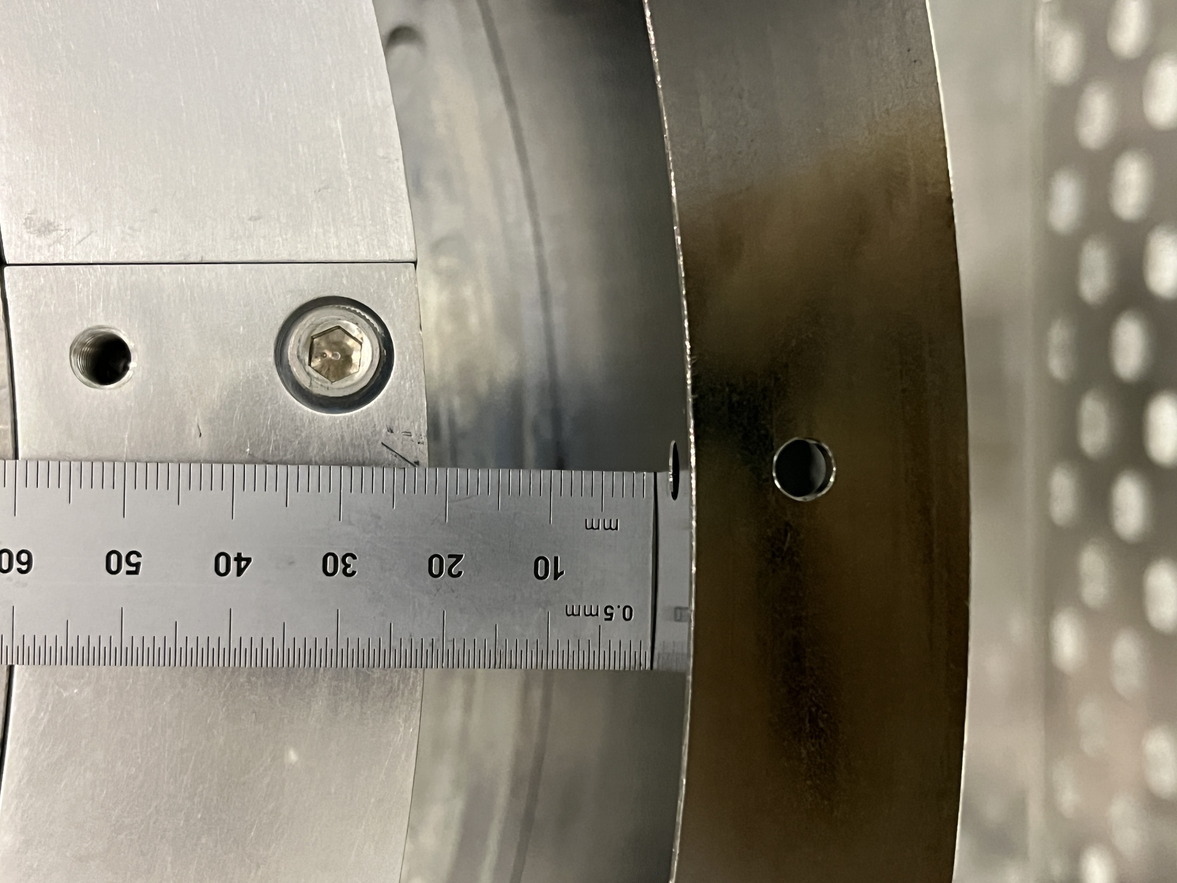
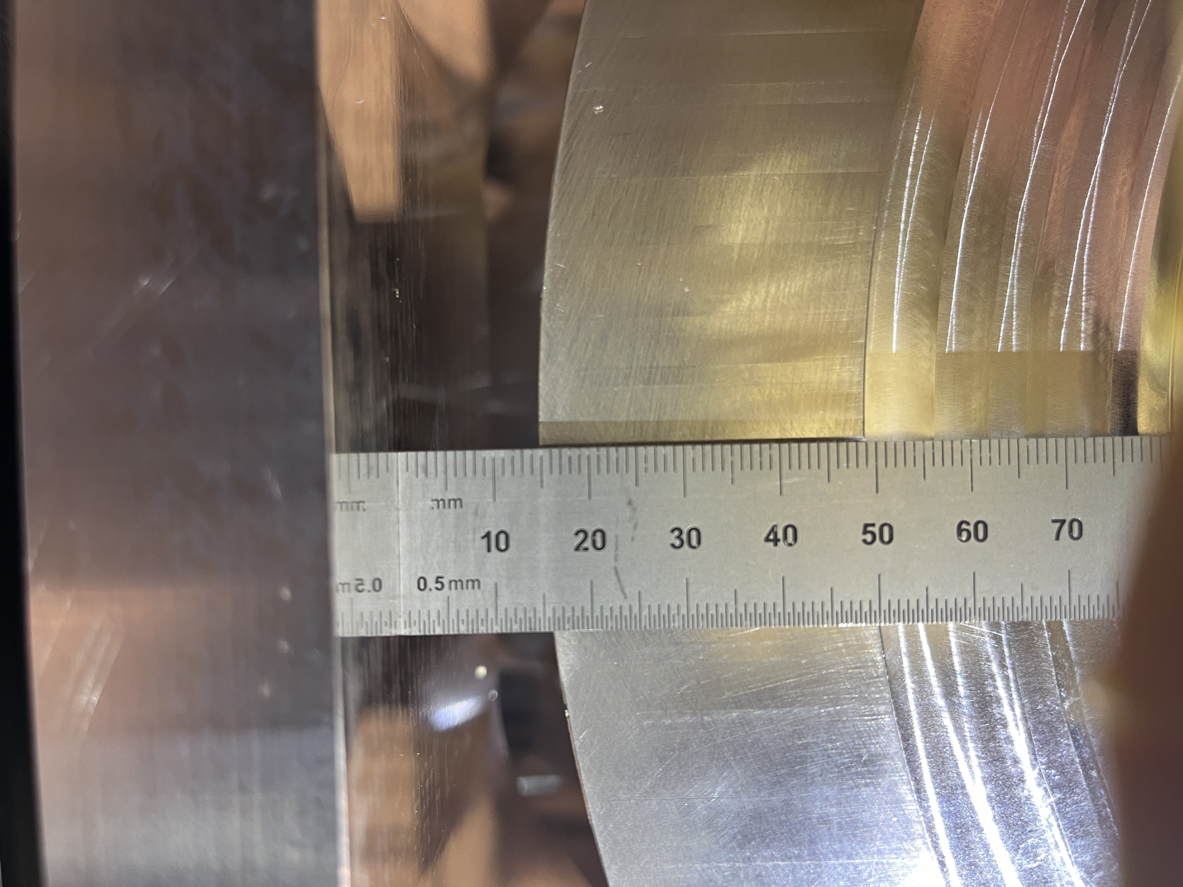
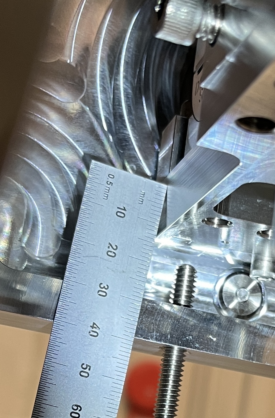
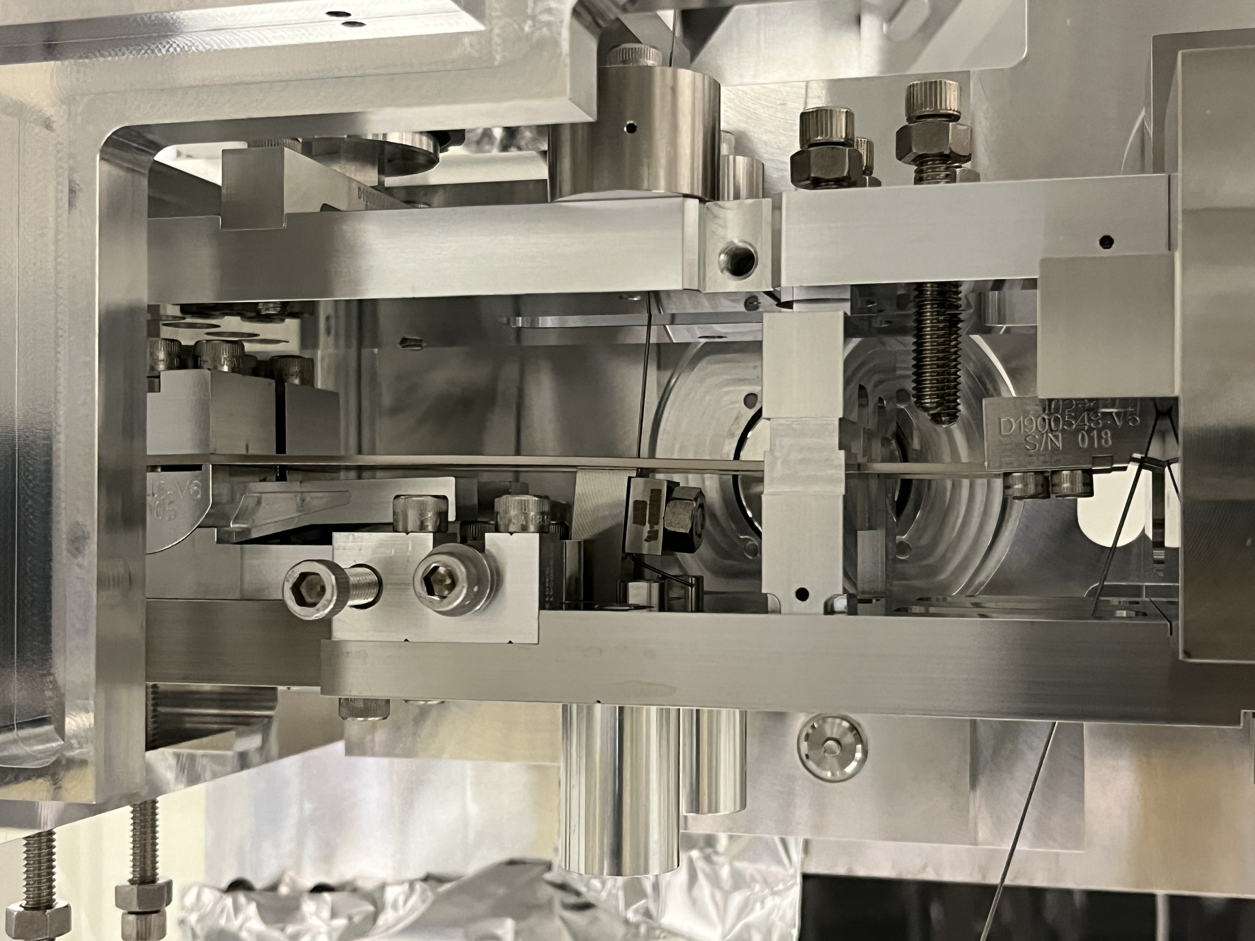
Today, Ibrahim and I made measurements of the BBSS Suspended masses compared to the dimensions shown on the various sheets of BBSS TOP LEVEL ASSEMBLY drawing D1900628. The BBSS is still nicely hung from the last RAL visit, very little pitch error by eye. It seems that all of the Top Mass, Penultimate Mass and Bottom Dummy Mass are 2mm low compared to the structure, together in the same direction, all ~2mm low. On the various sheets it shows reference nominal dimensions which we compared the as-built to (see attached). So, it seems that any overall height adjustment to the new suspension, if needed, would be in the upper stages.
tagging EPO for BBSS pics.
Update on these results: 76071
Verification that the d4 value is correct: 82138
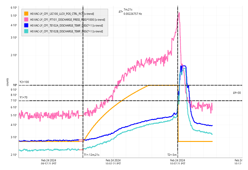
Sat Feb 24 10:07:21 2024 INFO: Fill completed in 7min 17secs
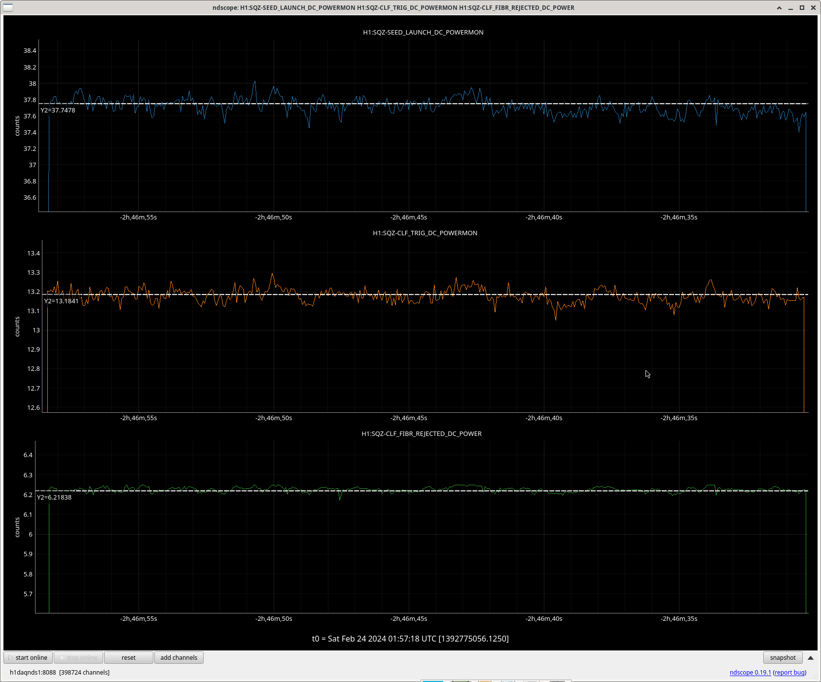
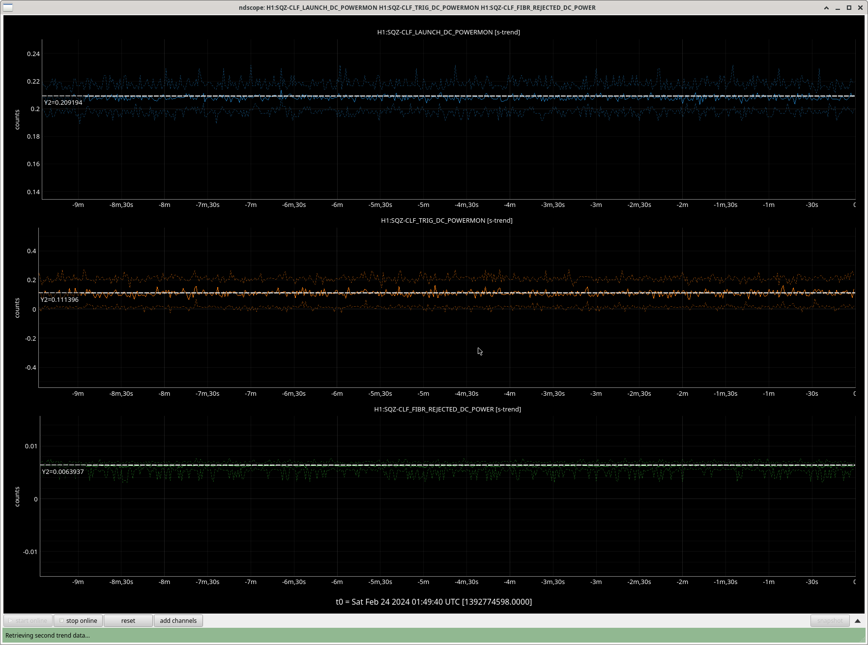
Naoki, Vicky, Nutsinee
Today we successfully realigned seed and CLF back into the coupler. Both have ~50% fiber throughput from SQZT0 to SQZT7. This includes the fiber switch lost. Seed was so misaligned that we needed to plug the seed fiber into pump output to get the green light out of the seed coupler to help with the alignment. We adjusted both the alignment mirrors and the fiber coupler Ztheta adjuster.
Yesterday we found out that our PMC was not that touchy. PMC guardian looks at PMC refl normalized current to check if it's still locked. The value we gave it was so marginal that every time we bump into something the PMC would think it had lost lock and started scanning. We've since increased that threshold from 0.4 to 0.6. Now we are able to pico the steering mirrors into the SHG without losing PMC lock. Naoki managed to get the green output back to 60mW with those.
We also calibrated seed launch and PMC trans (PMC trans was actually done yesterday).
BNC to HV adaptor has been returned to the OPO PZT.
Also got a proper measurement of FI rejected beam. About 50% of the SHG input comes back to the FI. Only a few tens of uW of green light measured with the bandpass filter.
The seed launch power changes as the flipper goes up and down. More power is being rejected in HAM7 now compared to when we closed out. Something to revisit on Monday.
Participants: Marc Dripta & Tony.
Tested the H1:CAL-PCALX_RECEIVERMODULETEMPERATURE with a break out board that has jumpers to "open" or "close" a particular pin on a circuit today.
We applied an external source of power to the temperature sensor circuit to try to determine if the temperature sensor noise is due to the power supply or not.
We plugged in the break out board and moved the jumper to open the circuit on pin 6. This removed the voltage source from pin 9.
Then we sent in 0V to pin 6 from the martel, and saw temperature sensor go down to ~ -270. which make sense because there was no longer any voltage on the pin.
We then put 9V on pin 6 with the Martel.
We then put 9v on pin 6 with a 9V battery.
and finnally we put everything back to nominal to compare.
The results of this test were inclonclusive due to all 3 power sources looked the same.
Marc had mentioned the idea of leaving a martel down there for 5 hours will reduce strange fluctuations of voltages over the day.
Also I turned the PCAL LASER back on. The VEA is still in Laser Safe.


Vicky, Jenne, Jennie W, TJ
Today we got the PSL beam back after the vent work and the new OMC has been installed so we tried to do some 'single bounce' mode scans of the OMC where we bounce the PSL beam off one ITM (in this case X).
We can see flashes in OMC transmission on the DCPDs.
The beam going into the OMC can be centred on ASC_AS_A,B WFS using the DC centering loops. Once this in done flashes can be seen on the DCPD_SUM_OUPUT meaning the cavity is going through some modes. Vicky also tried aligning the OMC and OM3 suspensions. After trying hand alignment, we realised that the OMC trans camera was not showing any flashes, despite seeing them on the PD.
According to Camilla it is perfectly possible this camera was not aligned to the OMC transmitted beam after the OMC swap, but it is plugged in.
As this would require laser hazard (and therefore WP) we proceeded with other efforts from the control room first.
We tried turning on the OMC ASC loops. This makes several of the ADCs on the OMC suspension output rail before the loops converge. They tried offloading the alignment onto the DC centering loops but the YAW degree of freedom in the ASC loops does not converge.
We also reset the offsets in the QPDs to the nominal ones used during the run and changed them till there was no offset at the output. When the servo is switched back on we expect the loops to drive the outputs to zero but the yaw degree of freedom still diverges away.
We reverted the OMC servo changes we made before leaving.
On Monday we will re-align the camera to check which modes we are aligning to and check more into the OMC loops to figure out what is going wrong.
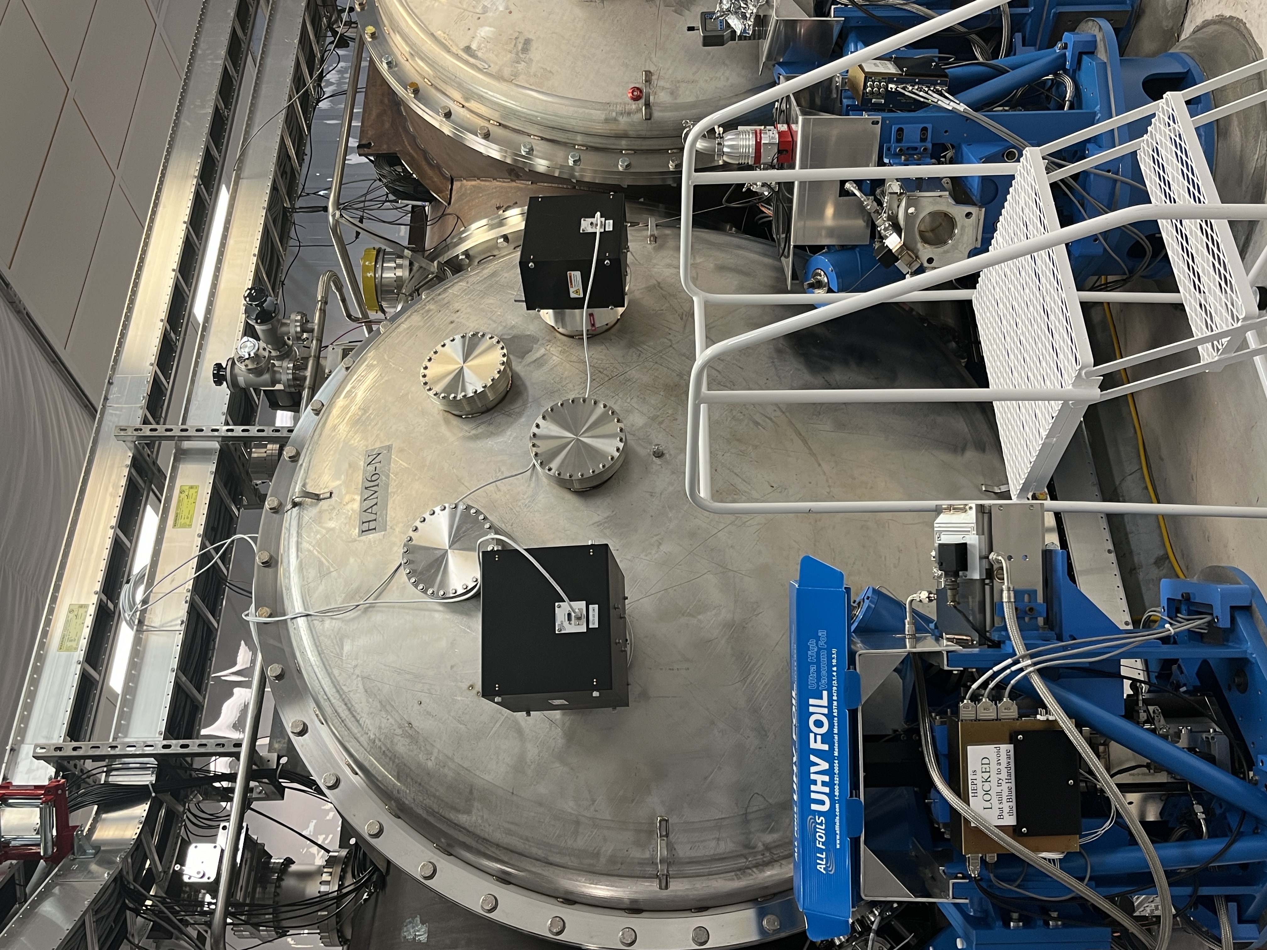
Today's activities:
- HAM7 pumpdown status: ~7.7E-7 Torr
- Corner pumpdown: ~6E-7 Torr, ~73 hours after the HV pumping started
- EX pumpdown status: 2.9E-8 Torr. The GV will remain closed during FAC works (1-2 weeks)
- At the EX RGA the bakeout temperature has been ramped up to 150 deg C; in the upcoming days the HAM7 and HAM8 RGAs will also be baked, as per WP #11713
- The pumping cart was disconnected from the GV5 annulus system
- The relay tube has been installed, see attached photo
- The relay tube is being pumped, at the moment is already at 2.4E-6
- The relay tube was leak checked, and everything is OK

TITLE: 02/24 Day Shift: 16:00-00:00 UTC (08:00-16:00 PST), all times posted in UTC
STATE of H1: Planned Engineering
SHIFT SUMMARY: The light pipe was unshuttered and we now have light in the corner station vacuum. We locked the IMC following the usual wiki instructions, with a restoring of the MCs helping to bring the mode cleaning back to a good state. Work is ongoing to get good light into the OMC for measurements.
LOG:
| Start Time | System | Name | Location | Lazer_Haz | Task | Time End |
|---|---|---|---|---|---|---|
| 19:22 | SAF | LVEA is Laser SAFE | LVEA | NO | LVEA is Laser SAFE | 03:59 |
| 16:12 | FAC | Karen, Kim | FCES | n | Tech clean | 16:41 |
| 16:41 | VAC | Jordan | EX | n | RGA check | 17:03 |
| 16:52 | FAC | Kim | LVEA | n | Tech clean | 19:54 |
| 16:57 | VAC | Travis, Jordan | LVEA | n | Relay tube prep | 19:54 |
| 16:58 | - | Camilla, Betsy | LVEA | n | HAM6 Camera viewport | 17:57 |
| 17:16 | FAC | Randy | LVEA | n | Craning over the tube | 17:57 |
| 17:48 | - | Mike | Opt Lab | n | Looking for a place to sit | 17:56 |
| 17:50 | IAS | Jason, Ryan C | LVEA - BG | n | Survey work | 20:11 |
| 17:57 | SQZ | Nutsinee, Naoki | LVEA - SQZ | LOCAL | Table work | 20:11 |
| 18:05 | PCAL | Tony, Dripta | Opt Lab | local | Responsivity meas. | 19:35 |
| 18:12 | SQZ | Camilla, Julian | Opt Lab | local | SHG work | 20:37 |
| 19:54 | ISC | Vicky, Jenn* | CR | n | OMC scan | 21:43 |
| 20:49 | VAC | Travis | LVEA | n | Connect leak check pump cart to relay tube | 21:16 |
| 20:54 | VAC | Jordan | EX | n | Check RGA | 21:21 |
| 21:10 | VAC | Janos | LVEA | n | Checks | 21:17 |
| 21:12 | SQZ | Vicky, Naoki, Nutsinee | LVEA - SQZ | LOCAL | Table work | 23:45 |
| 21:14 | IAS | Jason, Ryan C | LVEA | n | Survey | ongoing |
| 21:19 | SQZ | Camilla, Julian | Opt Lab | local | SHG work | ongoing |
| 21:36 | VAC | Travis, Jordan | LVEA | n | Relay tube leak check | 22:24 |
| 22:21 | PCAL | Tony, Dripta, Marc | EX | n | Temperature sensor troubleshooting | 23:00 |
| 22:49 | CDS | Fernando | EX, EY | n | Oplev hardware install | ongoing |
| 22:50 | - | Mike | LVEA | n | Check on relay tube | 22:56 |
| 22:57 | VAC | Travis | LVEA | n | Adjust setpoints for pump cart on relay tube | 23:27 |
| 23:51 | VAC | Jordan, Janos | EX | n | Vac check | ongoing |
Dana, Louis
I tried generating the calibration report for report ID 20231011T202627Z but was unable to do so. The following error was returned:
ValueError: ('There are no common frequency points for the ', 'two transfer functions. Maybe check coherence', ' thresholds.')
For the full error message, see attached txt file.
I try to investigate this error. It seems that there are no data, frequencies, tf...etc. extracted from both DARMOLG_SS_20231011T202627Z.hdf5 and PCALY2DARM_SS_20231011T202627Z.hdf5. This make this error appear. For example, freq_meas1 and freq_meas2 in measurement.py L366 and L370 becomes empty, so frequencies variable in L394 is empty. The attached file is to reproduce this error.
This morning, I set the alarm levels for DM6 back to their higher threshold values of 7k counts minor and 10k counts major for both 0.3u and 0.5u since doors are back on HAMs 5/6/7.
The levels for the other DMs have already been set back (alog75671), so all LVEA DMs are now back to their Class-10k thresholds.
Matlab2023b is now available from any CDS workstation by running 'matlab2023b' from a shell.
Before the LVEA was transitioned to Operations version of laser safe, I removed the beam dump blocking the CO2X beam from getting to the perescope that was installed while doing the CO2X swap alog 75550.
WP 11696 Betsy and I replaced the two HAM6 +X cameras removed in alog75425. Guillotines also removed will need to be reinserted if camera alignment needs to be adjusted.
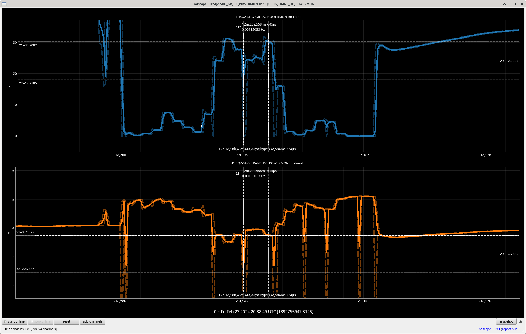
I just ran a script that sweeps SHG crystal temperature. This test requires TTFSS, PMC, and SHG locked. PLEASE DO NOT TOUCH THE SQUEEZER. PLEASE WALK GENTLY NEAR SQZT0. The duration of the script is ~2hrs. Star time is 16:40.
The script sets the crystal temperature from 29C - 41C at 0.5C increment. We hope to replicate the phase matching curve done by a SURF student Nathan Zhao (P1400193 Fig 23). The script can be found in /opt/rtcds/userapps/trunk/sqz/h1/scripts/SHGphasematch.py
Here's our Sinc function. Not sure what's going on with the dip in the middle but I believe we have been operating at a good place (the right peak, ~36C). Although after the temperature scan the green production didn't come back to where it started. I moved the crystal temperature to the middle of the sinc function to confirm that the conversion efficiency really went down. I then moved the crystal temperature to the left peak of the sinc function (~34 C) and managed to recover 10mW of green.
Something else is drifting as well and it seems to have nothing to do with me. PMC PZT ran out of range this morning so I expanded the scan range down to 0V temporary (the current lock triggered at ~25 V). SHG PZT is still drifitng as I'm writing this alog while the green conversion goes down with it. For now I decidede to park the crystal temperature at 33.78C. Changes accepted in the SDF.
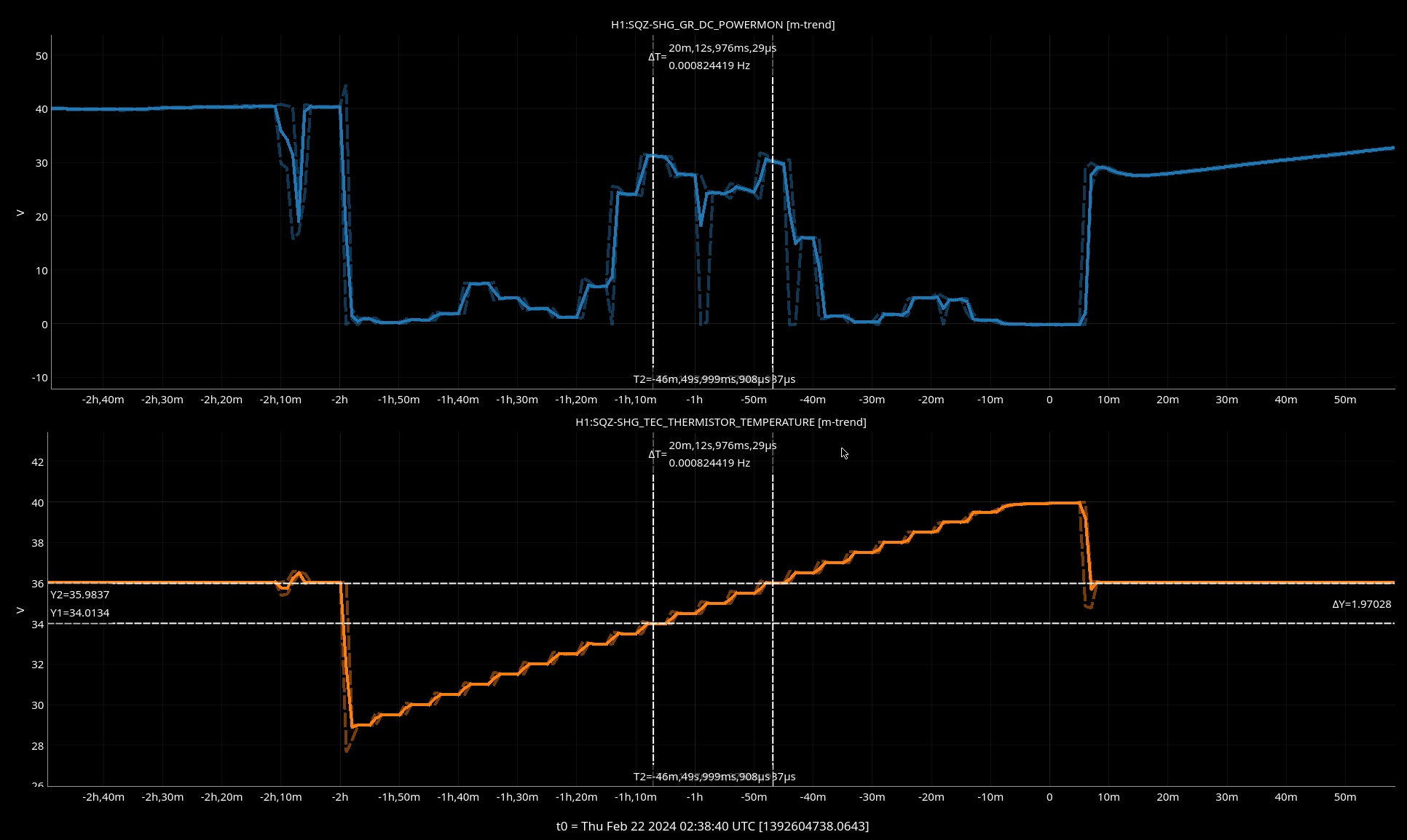
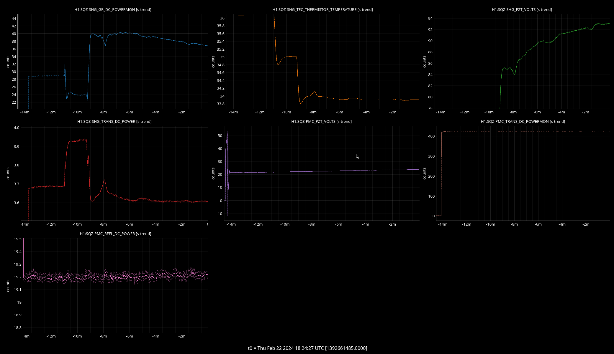
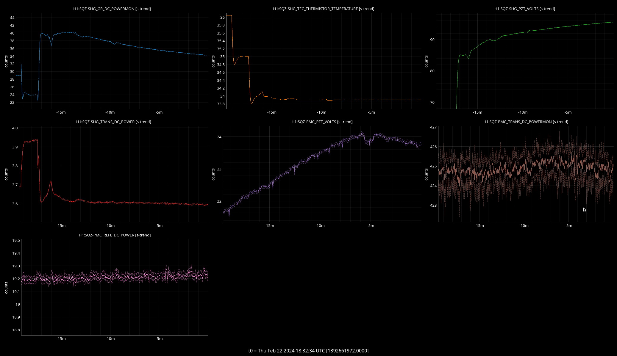

Attached a plot with SHG red transmission.


