Jonathan, Dave, Fil, Erik, Tony, Ryan,

As part of WP 11698 we upgraded and replaces switches at EX, EY, MX, MY, upgraded the link to the FCES, and did some work on sw-mech-aux that we had to revert.

At EX we removed sw-ex-h1fe, sw-ex-aux and replaced it with two units (icx 7150) joined as a switch stack named sw-ex-stk.
At EX we removed sw-ey-h1fe, sw-ey-aux and replaced it with two units (icx 7150) joined as a switch stack named sw-ey-stk.

Last week Fil ran fibers between the vacuum rack and the electronics/FE rack at each end station.  We used these fibers as the switch stacking links.  Three fibers where run at each location, we used fibers 1 and 3 as the number match the stacking ports on the switches.

At each end station the stacking ports are mapped as follows (note the cross over of the interfaces between the switches):

VAC 1/3/1 -> Fe 1/3/3 (stacking fiber link #1)
VAC 1/3/3 -> Fe 1/3/1 (stacking fiber link #3)

The procedure was to:

 * Have the control room put the FE computers in a safe state
 * Erik then fenced the dolphin ports (turned off the ports on the dolphin switch) to help isolate any potential failures.
 * Rack mount the new switches, removing old equipment if needed.
 * Connect the stacking fibers
 * Then power on the switches in a coordinated effort.  We powered on the switch in the VAC rack, waited a few seconds and then powered on the switch in the FE/electronics rack.
   * It is desirable to have the switches come up at around the same time, otherwise the stack can take a long time to form.
 * Move all the fiber connections over.
   * On the VAC switch this was the fiber to the core switch going from fiber port 2 to 1/3/2 on the new switch.
   * On the FE switch this was moving 1/3/3 to 1/3/2 on the new switch, moving 1/3/4 to 1/3/4 on the new switch, and dropping  the 1/3/2 from the old switch.
 * Move all the copper connections over.
 * Test.
 * Clean up cables and fibers.

Fil installed a 24 port poe injector in the VAC rack at each end station to power the wifi and cameras.  We had one failed poe injector so Fil and Ryan got a new one from the EE lab.

At EX we had one FE crash, at EY all of them crashed.  The control room was able to remotely restart the systems we did not need to do anything special.
I did have to manually reset the IP address on the stack switches.  It looks like I left them in dhcp mode from the test setup.

At the mid stations the process was to:
 * Rack mount the new switch (icx 8200)
 * Move all the connections over
 * At this point we upgraded the link from 1G to 10G.
   * This required Erik to change the optic out in the old core switch while we where at the mid stations.

We were unable to get the wifi working via poe on the icx 8200 units.  Not sure why yet, it is supported.  We tested using a 24 port poe injector, but did not leave that in place.  We need to figure out the issue with the switch or put a single port poe injector in.

For the FCES we simply installed a 10G optic and moved the fiber to it.  Erik replaced the optic in the old core switch while this was done.  We did the FCES switch at lunch time as Jim Warner needed a functional CDS network in the afternoon.

We had issues with the mechanical auxiliary switch.  Due to the rack layout we were not able to install the switch below and work, which is our preferred method.  But we were able to get it mounted.  We found some issues that it would periodically drop connection after we had gotten the system going.  This is one of a few things 1. a spanning tree issue (not sure how/why as the port config is the same as MX/MY we should have seen an issue there) 2. the fiber is just not good enough for 10G (however we were not seeing a lot of errors on the ports).  In order to have a stable vacuum network we reverted the connection to the 1g link to the old cisco switch.

We wanted to move the new core to be 10G(+) only.  Not for bandwidth needs, but to simplify its config a little.  If it turns out that the fiber is not quite good enough for a 10G link, I ran a test afterwards using spare gear and the new core switch in the MSR.  The icx 7850 turns off auto-negotiation and requires a hard wired port speed config.  This causes issues as our other switches want to negotiate and so fail a negotation and I've had issues connecting a 1g link to the 7850.  It works fine if you hard code the port speed and turn off auto negotiation on the down stream switch.  So if I need to do a 1G link to the sw-mech-aux tomorrow with the core I would add the following line to the port config on the sw-mech-aux switch interface "gig-default neg-off".

Our work order was as follows:

End X
Mid X

lunch
FCES optic swap

End Y
Mid Y

mech aux switch work

Following that Tony and Ryan removed some old gear from the MSR (the old router that died, and an old spare switch just above sw-msr-ops) and rack mounted the new sw-msr-server2 and sw-msr-server3 directly below the switches will be replacing tomorrow.

We have not touched any of the daq switches (carrying the fast data stream from the front-end computers to the daqd system).  We hope not to touch them at all in this work.

Tomorrow we move to the MSR and will be interrupting the CDS network in general.
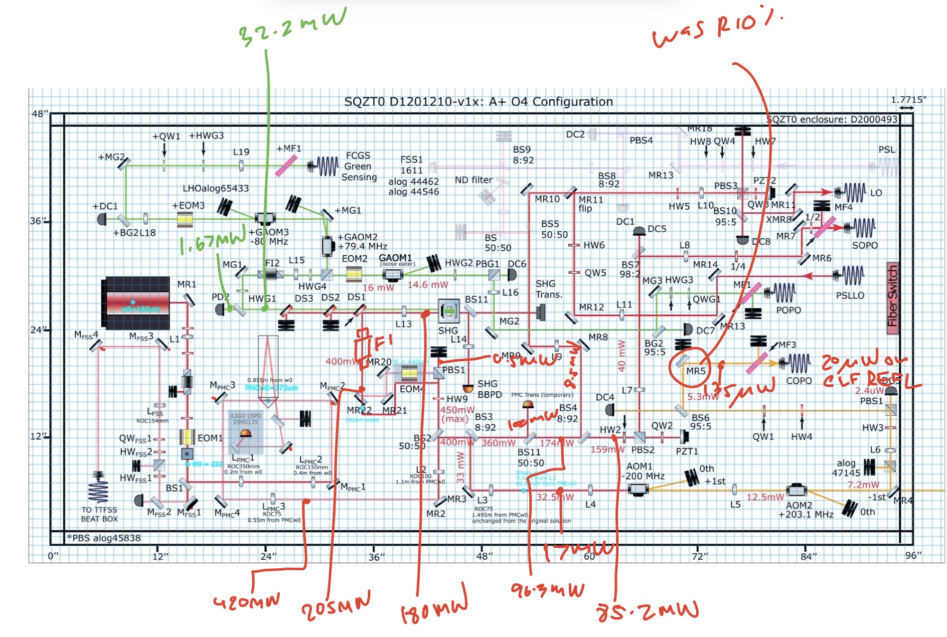
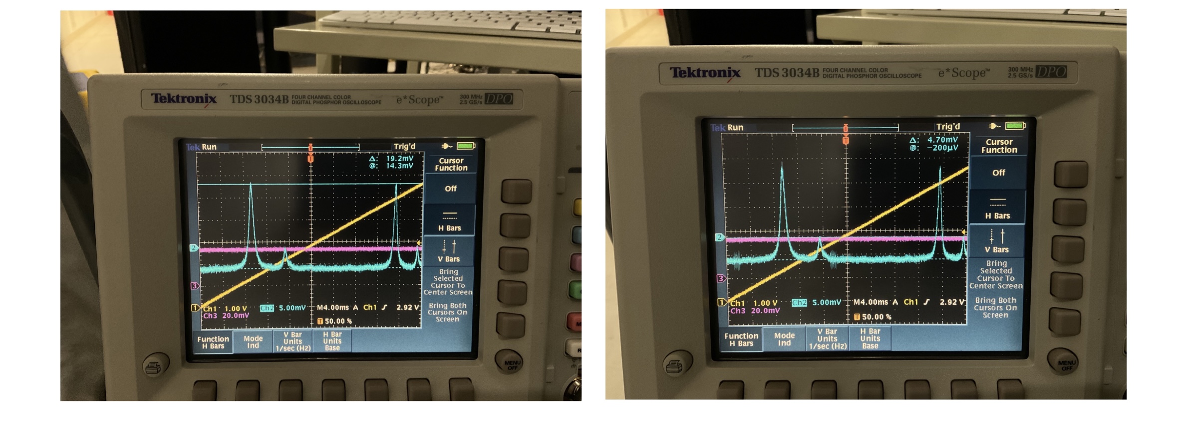
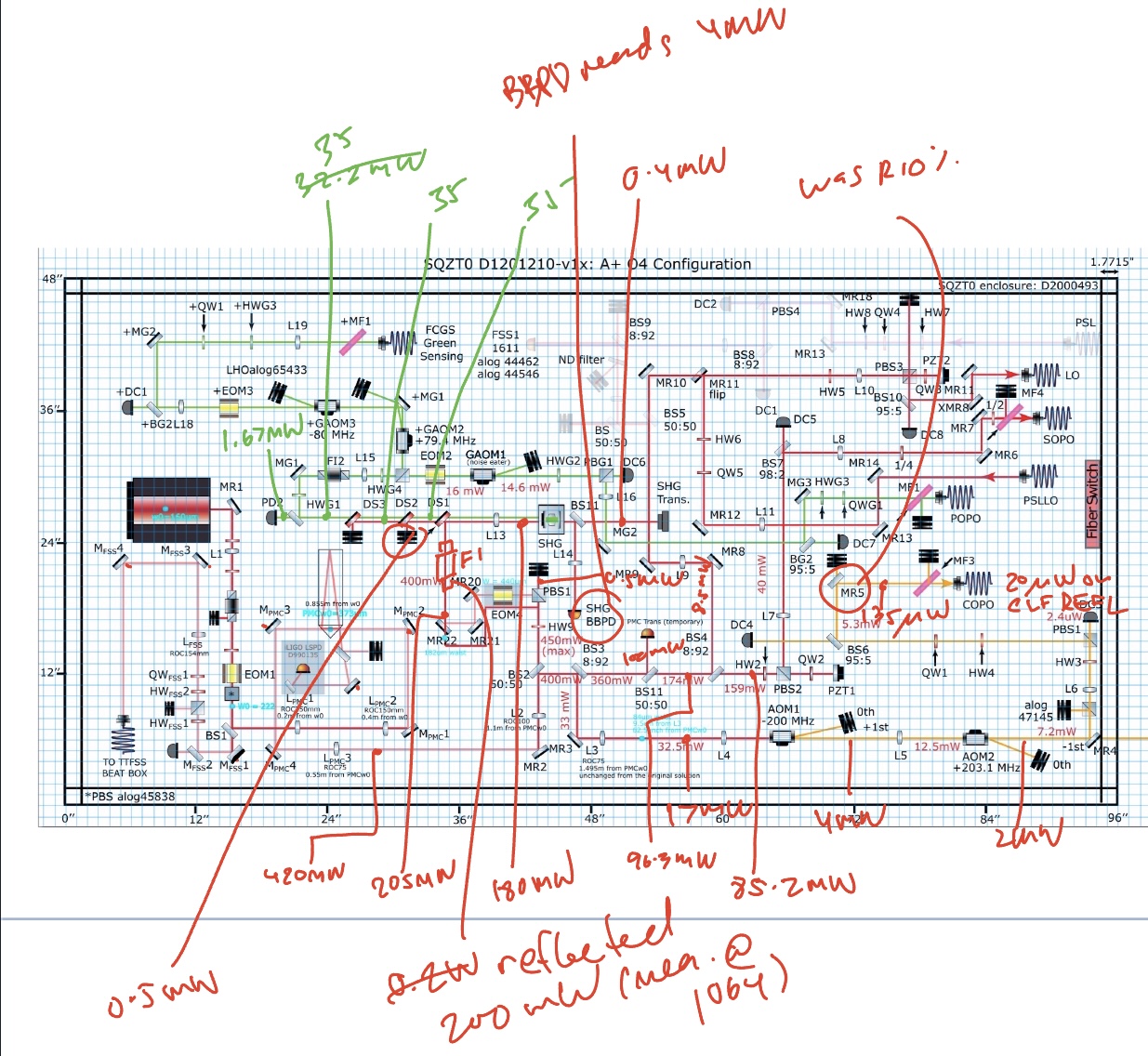
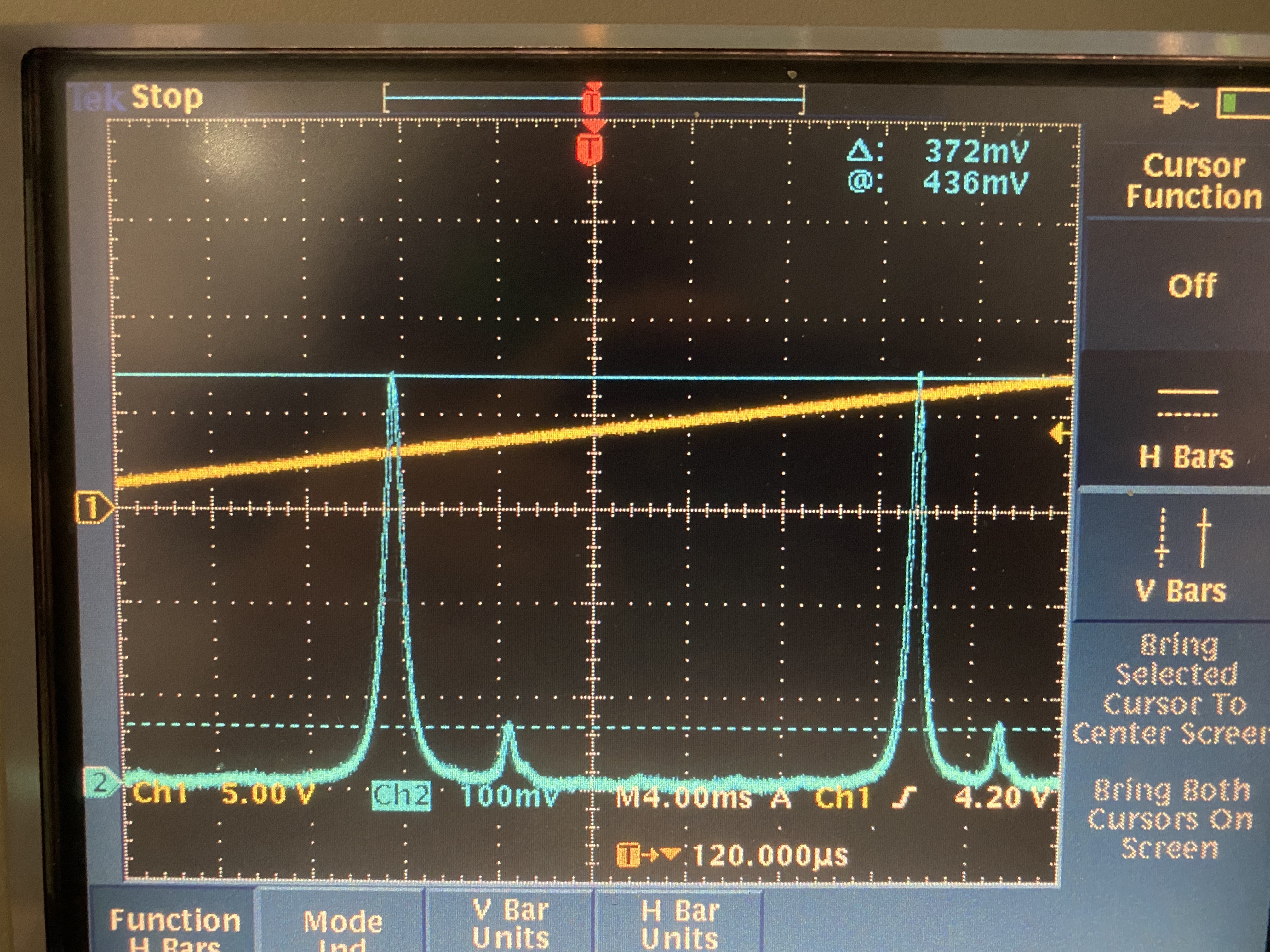
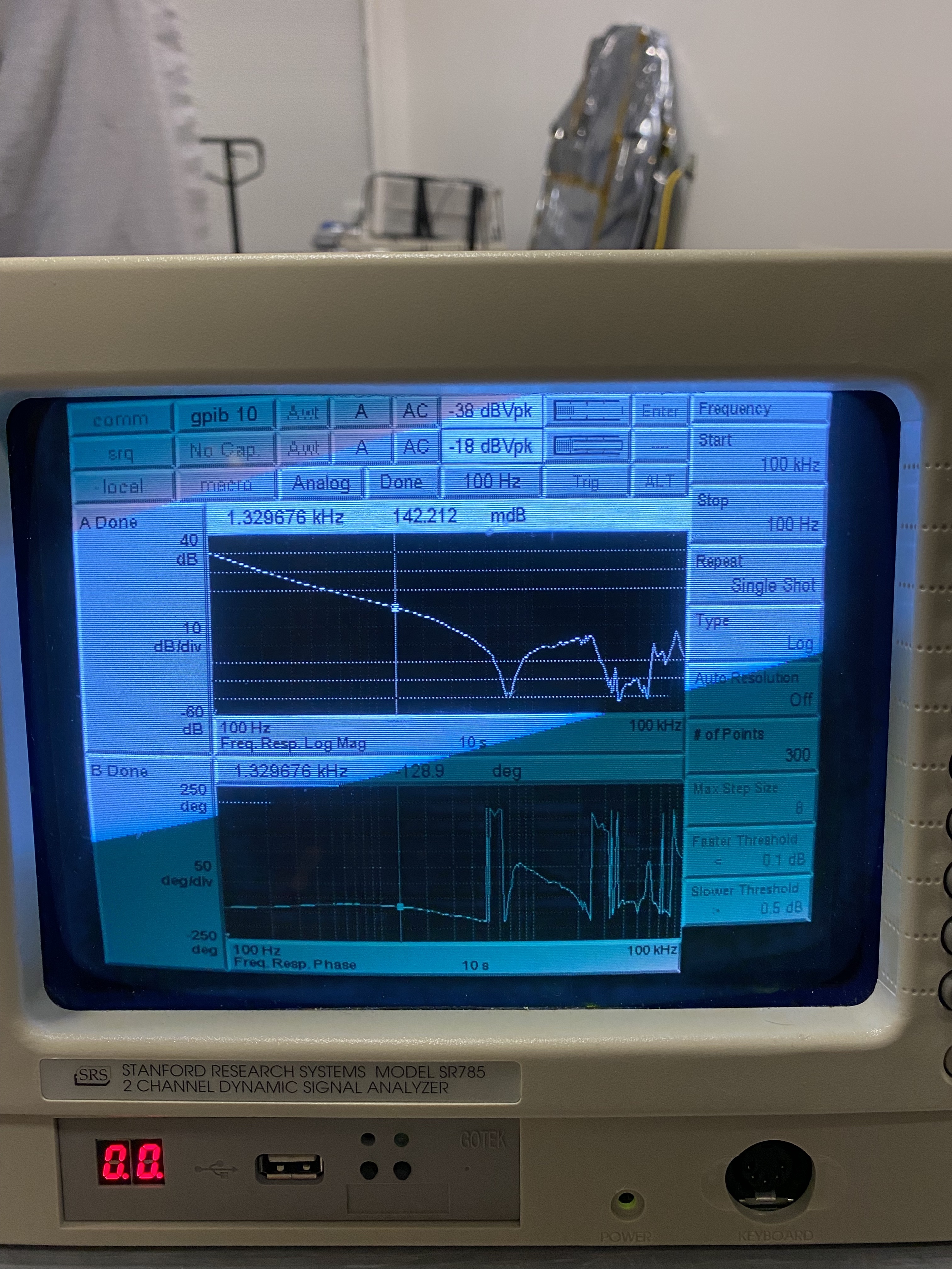
Here's our Sinc function. Not sure what's going on with the dip in the middle but I believe we have been operating at a good place (the right peak, ~36C). Although after the temperature scan the green production didn't come back to where it started. I moved the crystal temperature to the middle of the sinc function to confirm that the conversion efficiency really went down. I then moved the crystal temperature to the left peak of the sinc function (~34 C) and managed to recover 10mW of green.
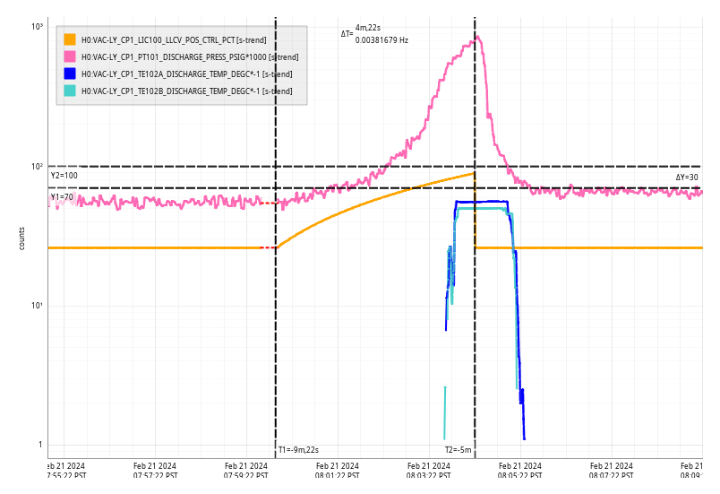
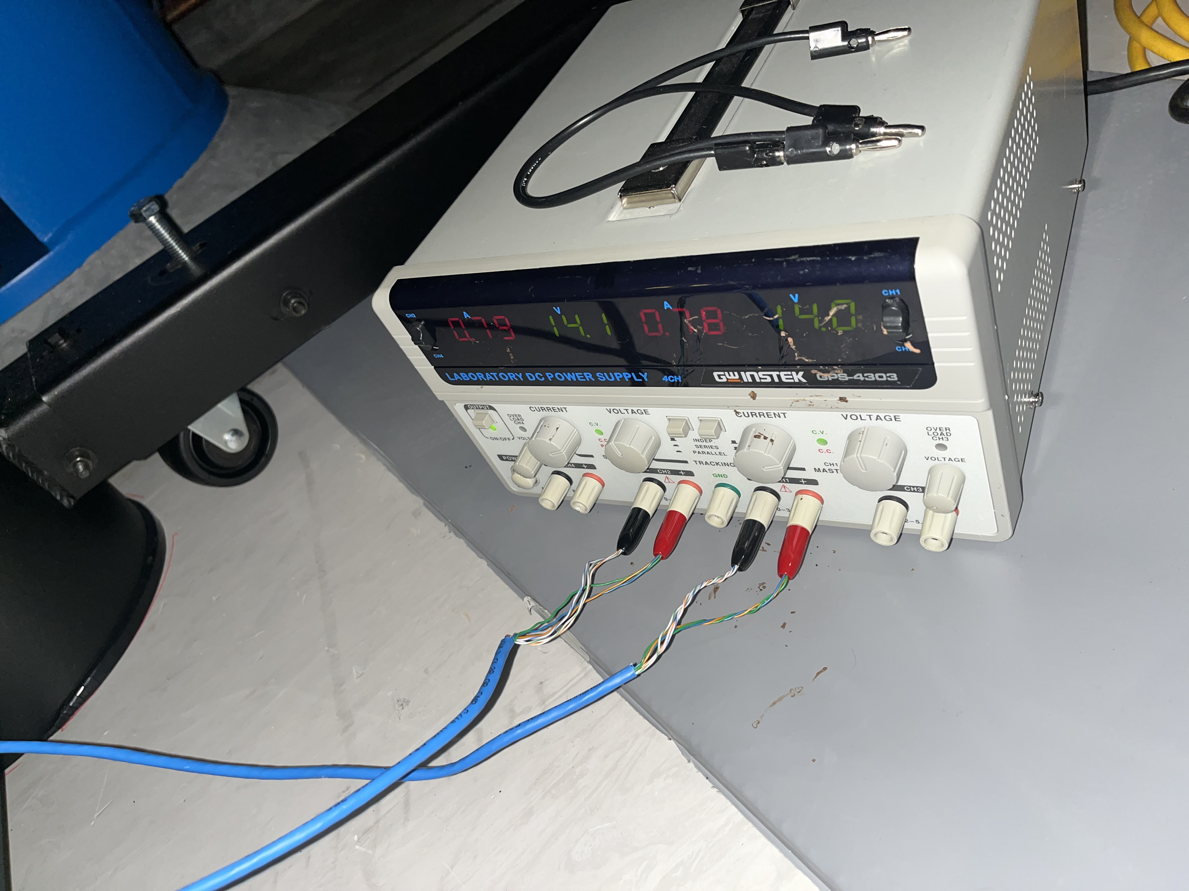
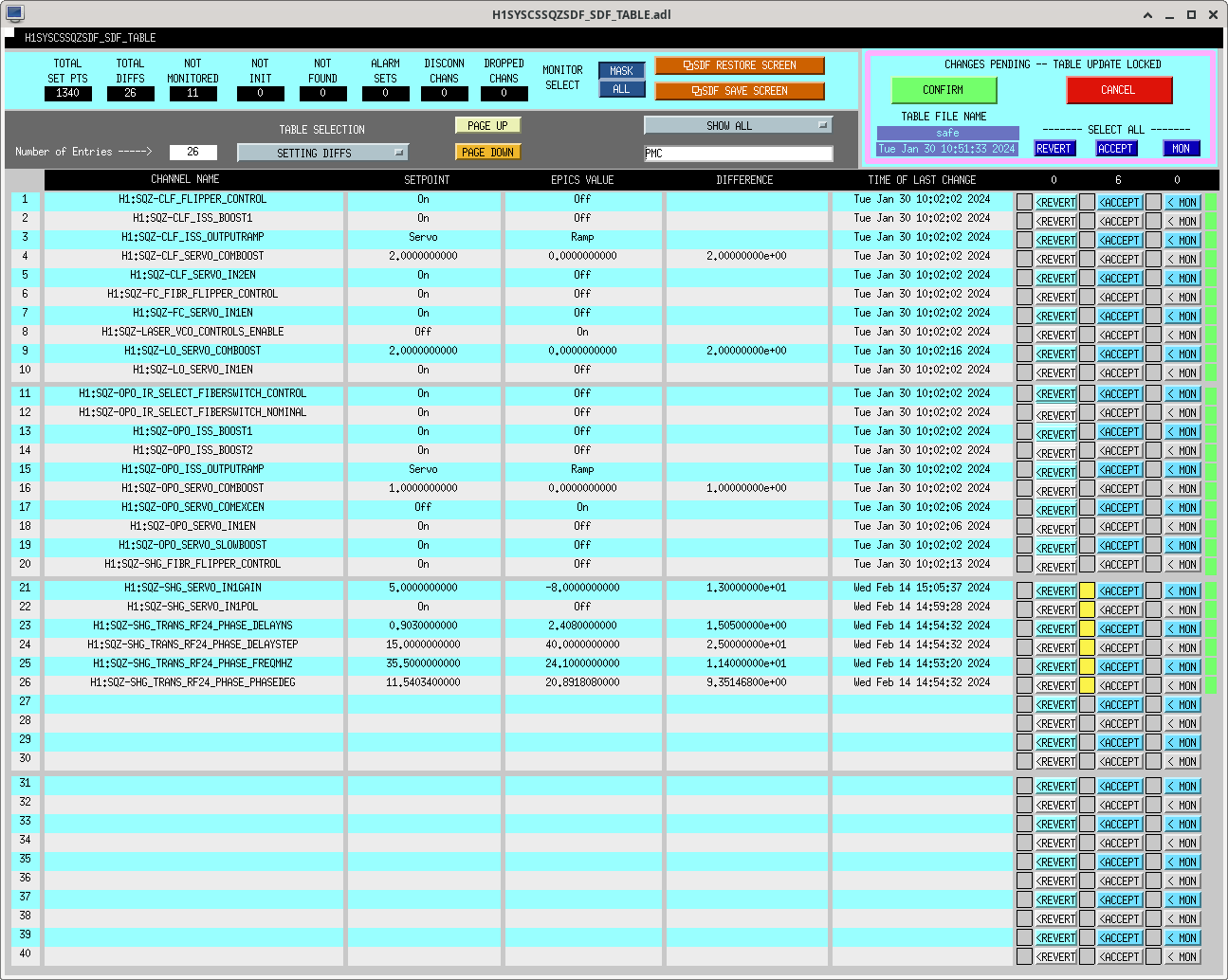
Something else is drifting as well and it seems to have nothing to do with me. PMC PZT ran out of range this morning so I expanded the scan range down to 0V temporary (the current lock triggered at ~25 V). SHG PZT is still drifitng as I'm writing this alog while the green conversion goes down with it. For now I decidede to park the crystal temperature at 33.78C. Changes accepted in the SDF.
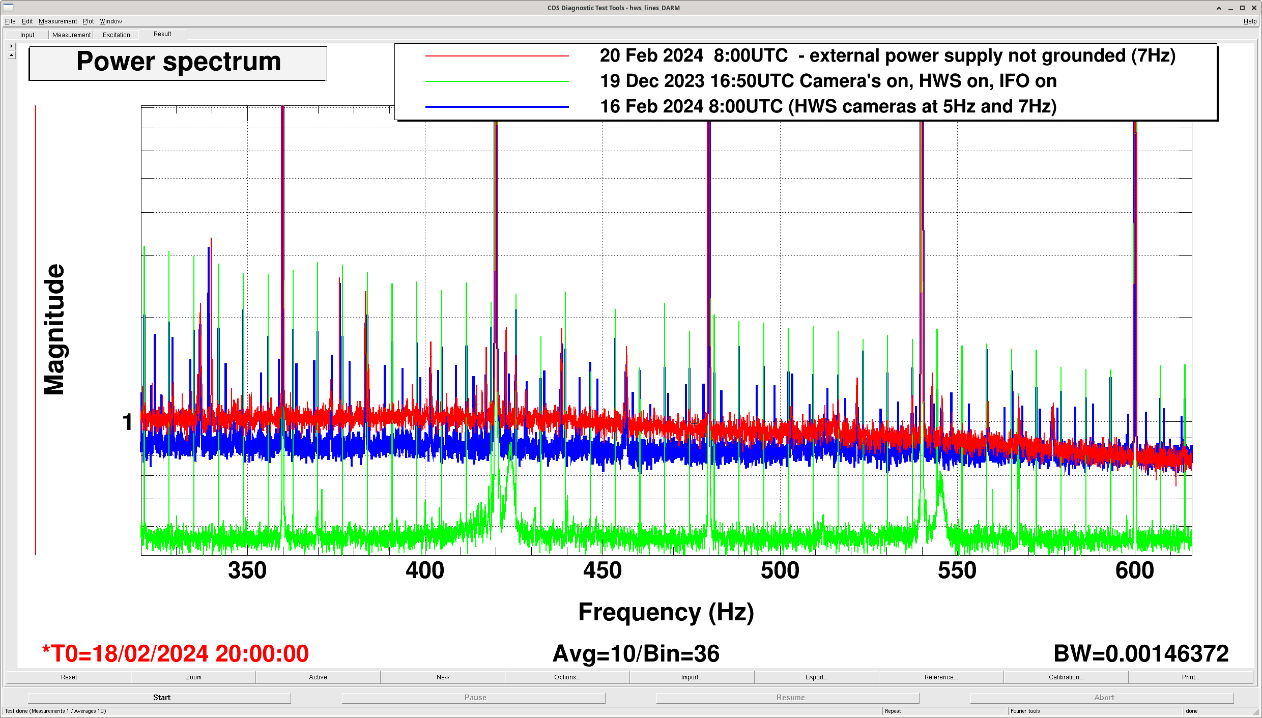
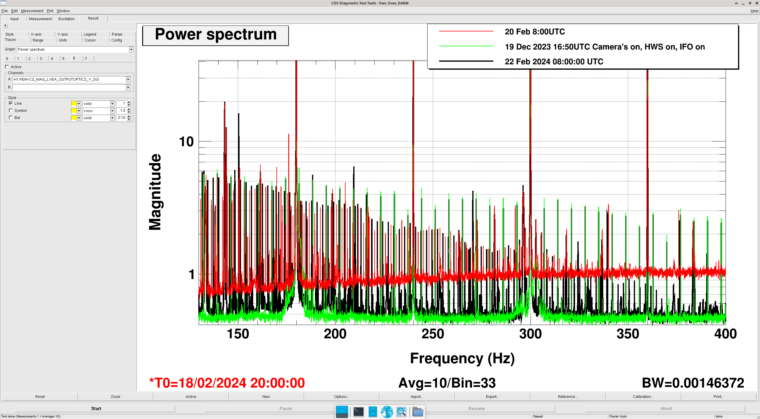
Attached a plot with SHG red transmission.