david.barker@LIGO.ORG - posted 10:29, Monday 12 February 2024 (75821)
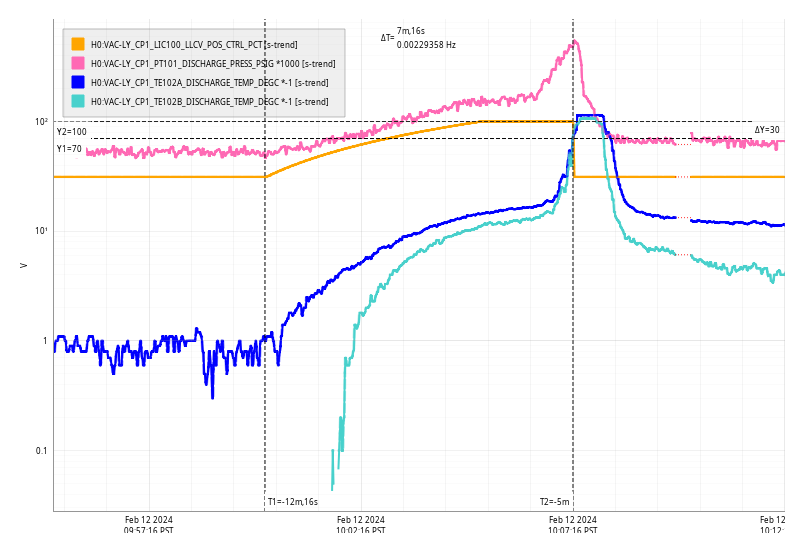
Mon CP1 Fill
Mon Feb 12 10:07:16 2024 INFO: Fill completed in 7min 12secs
Images attached to this report
Mon Feb 12 10:07:16 2024 INFO: Fill completed in 7min 12secs
TITLE: 02/12 Day Shift: 16:00-00:00 UTC (08:00-16:00 PST), all times posted in UTC
STATE of H1: Planned Engineering
OUTGOING OPERATOR: None
CURRENT ENVIRONMENT:
SEI_ENV state: CALM
Wind: 7mph Gusts, 5mph 5min avg
Primary useism: 0.02 μm/s
Secondary useism: 0.33 μm/s
QUICK SUMMARY:
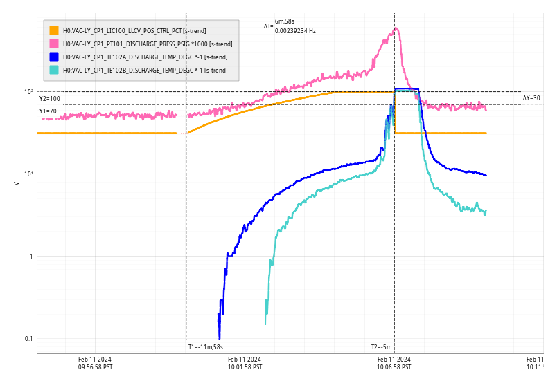
Sun Feb 11 10:06:58 2024 INFO: Fill completed in 6min 54secs
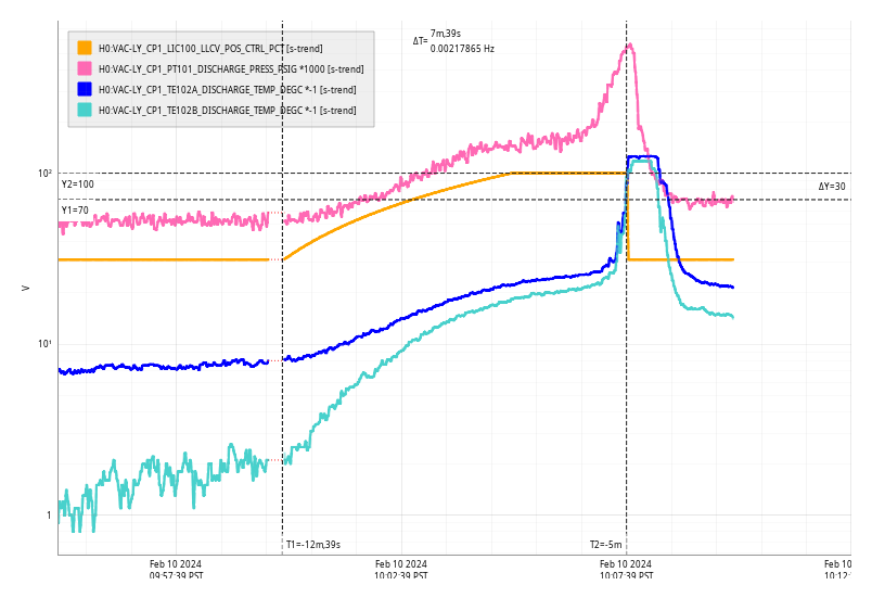
Sat Feb 10 10:07:39 2024 INFO: Fill completed in 7min 35secs
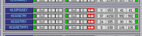
At 05:42:38 PDT this morning, Sat 10feb2024, all the models on h1susey had a single DAQ CRC error as detected by DC1, DC0 did not see any issues. Epics load mon trend of h1susey's DAQ network port does not show any issues around this time.
(Jordan V., Gerardo M.)
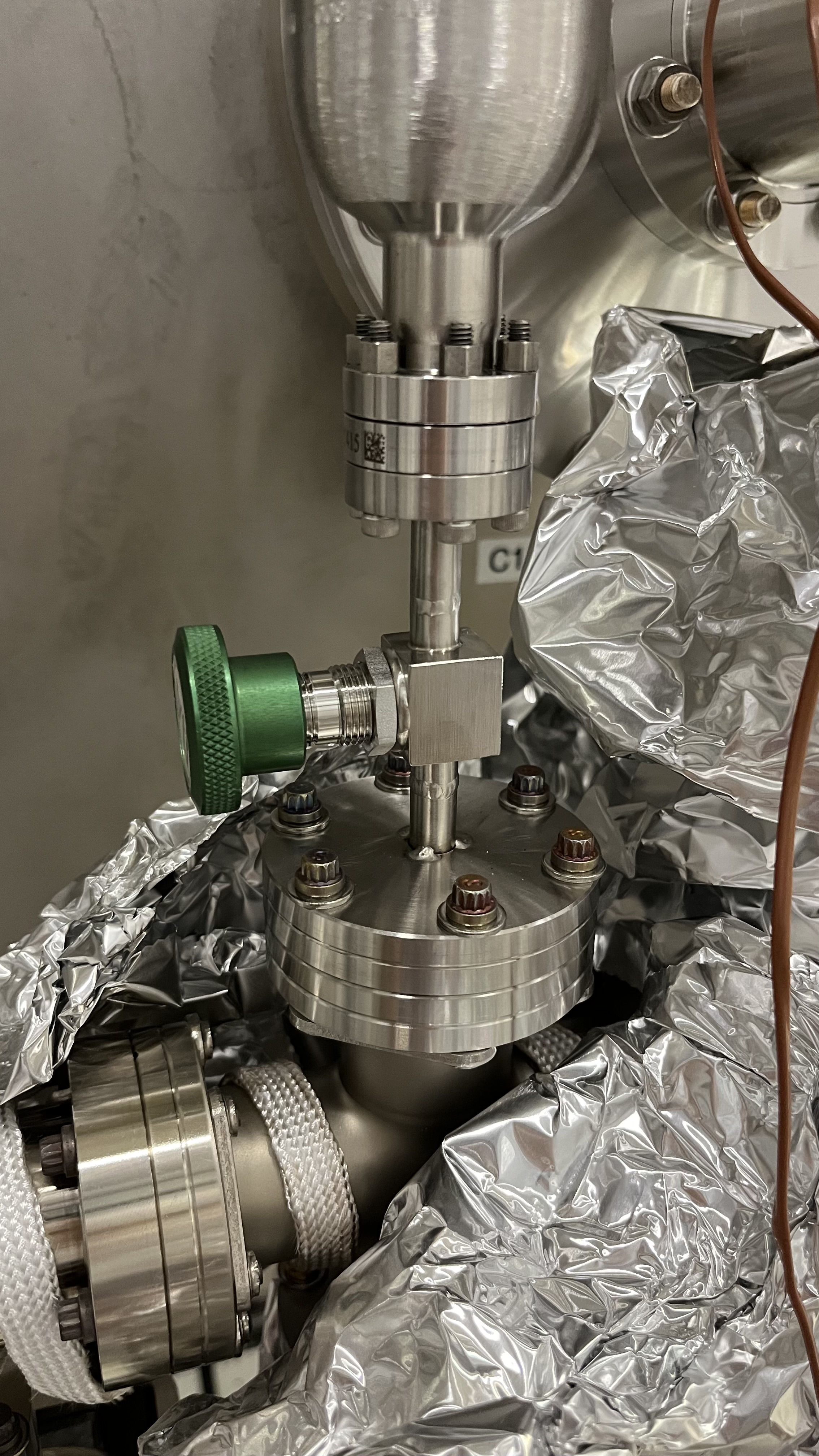
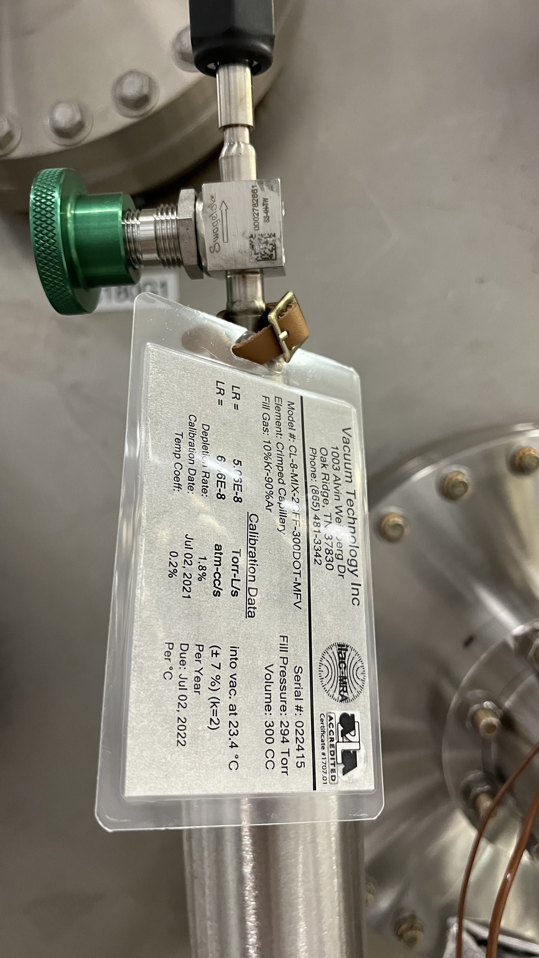
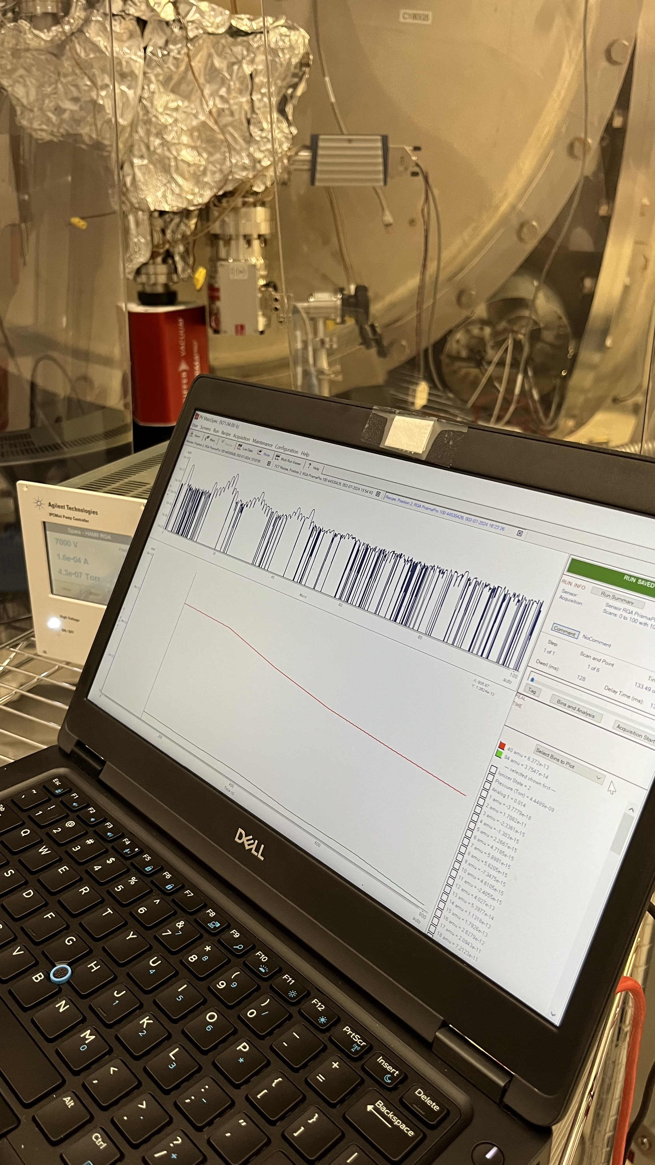
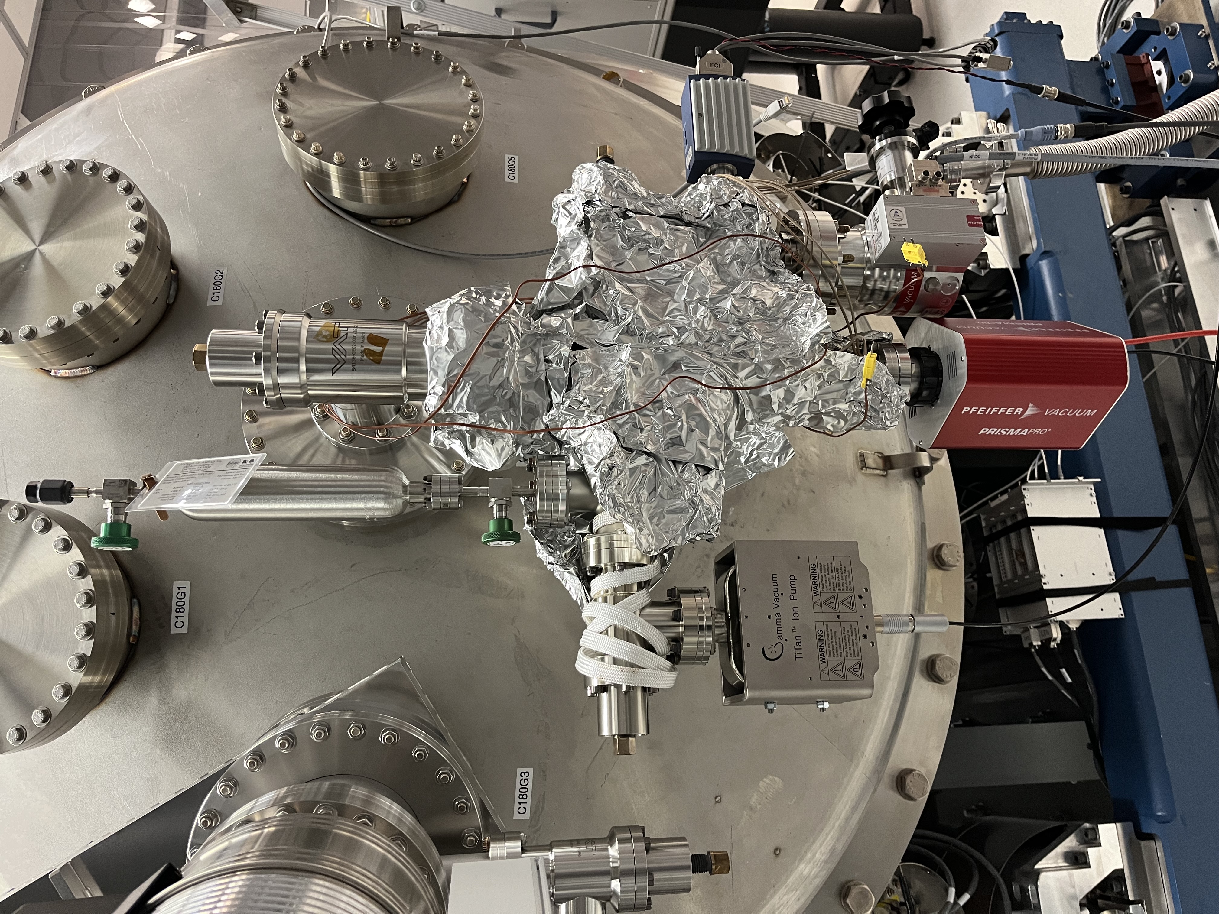
Late entry. The plan was to go and take an RGA scan "pre-vent" from HAM8.
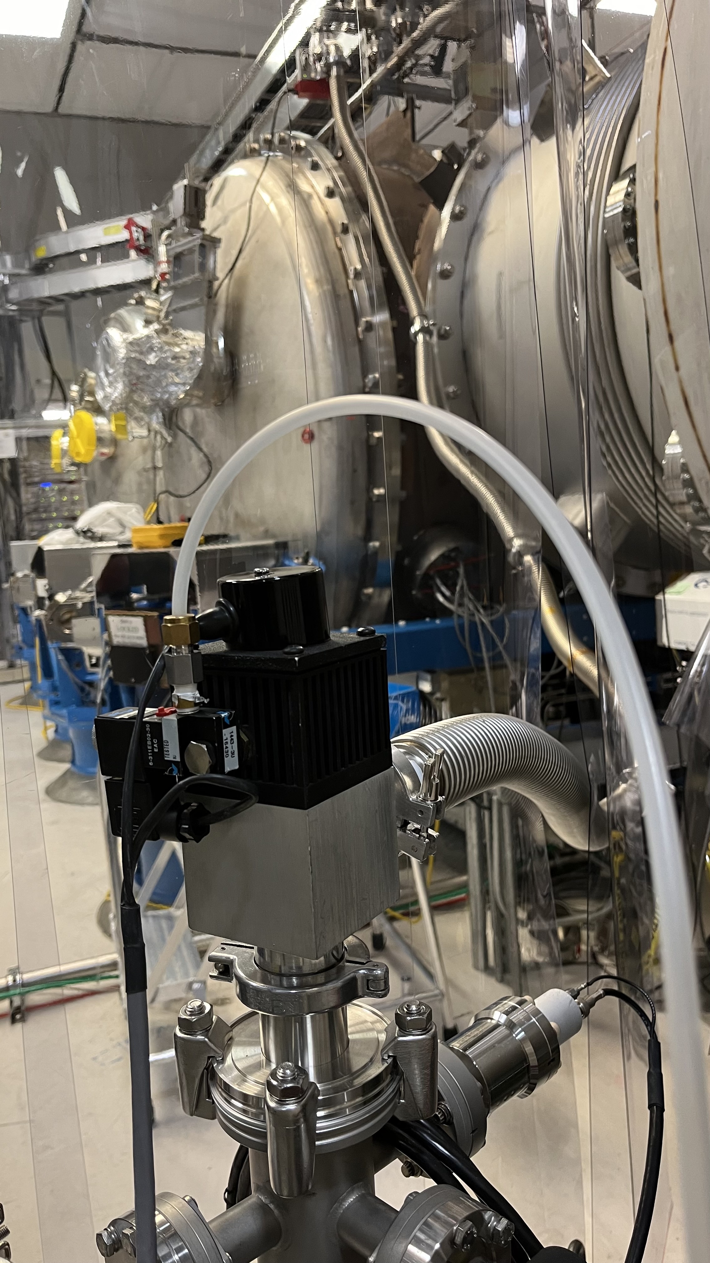
OnTuesday after lunch, we went to the filter cavity end station to power ON the RGA located on HAM8, the system has an active ion pump to maintain the RGA volume under vacuum, upon initial inspection all appeared nominal, the ion pump controller showed an internal pressure in the volume of the RGA system of mid 10^-07 Torr. We attempted to pump down the RGA system with an aux cart+can turbo combo, however once at nominal vacuum pressure the safety interlock for the aux cart would not engage, we stopped and left it be until the following day.
Second try on Wednesday, we diagnosed the aux cart, and for our luck it turned out to be a disconnected wire, with the wire connected the aux cart safety interlock was working. Then the RGA system was pumped down, once at nominal pressure the RGA filament was turned on.
Late Wednesday, a scan was taken of the RGA system alone, the scan had two prominent peaks that should not be there under the current condition, the peaks were for argon and krypton..
After some detective work, we determined that we have a leak on the isolation valve for the calibrated leak mounted on the RGA system!
Since taking the scan, the aux cart has been pumping down on the RGA system, we are trying to eliminate as much of the gases as possible, keeping fingers crossed it works, otherwise we'll need to bake the system to clean it up. More to come for this RGA.
WP 11673
Three singlemode LC/LC fibers were pulled at each end station. Part of the upcoming CDS network upgrade. Fibers pulled from the DAQ-C1 rack to the Vacuum Rack in the VEA.
Today's activities:
- HAM6 X+ X- doors have been closed, see details here: https://alog.ligo-wa.caltech.edu/aLOG/index.php?callRep=75810
- HAM6 and HAM5 common Annulus volume is being pumped
- EX pumping status: 6.3E-8
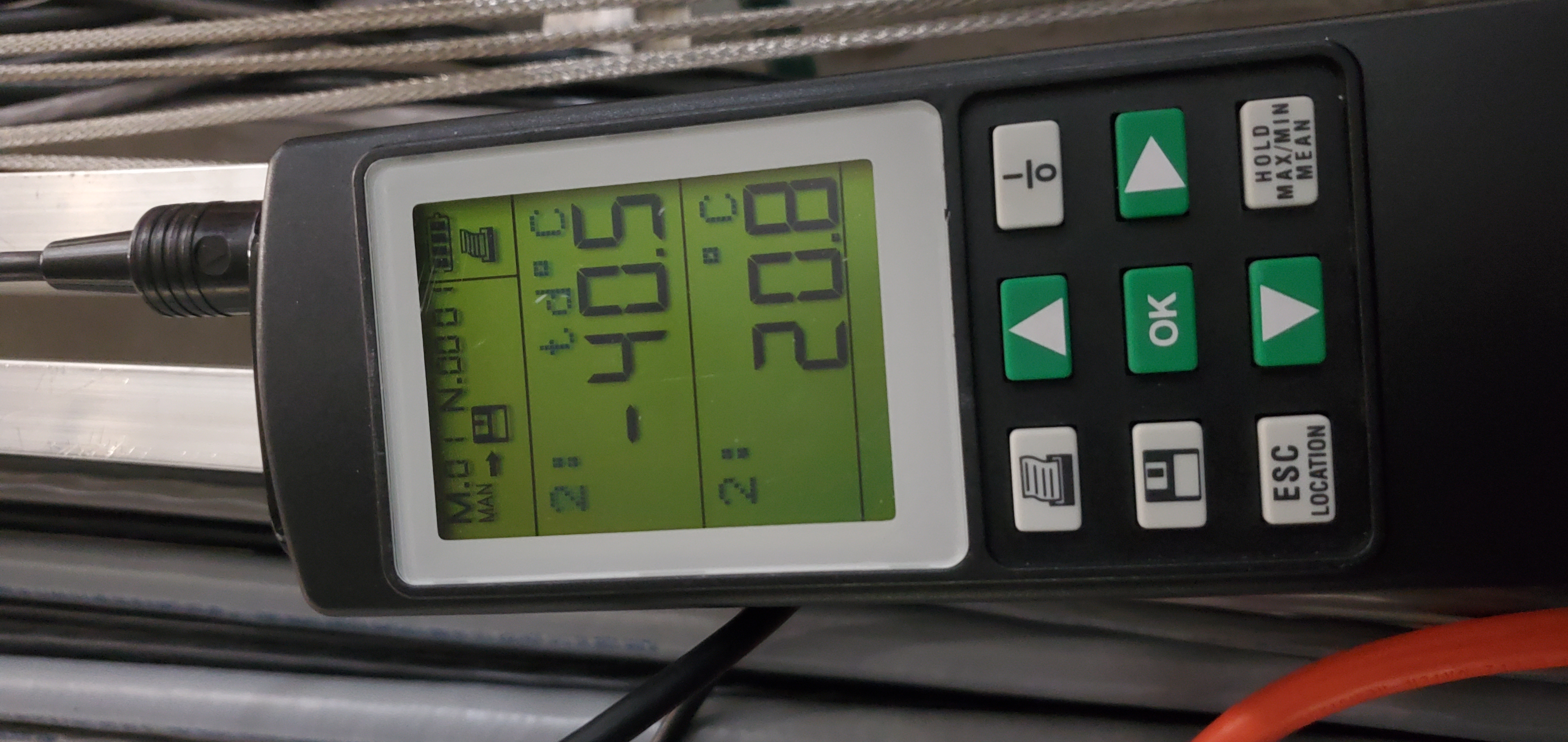
Today's purge air dew point measurement, taken prior to HAM6 door installation, -40.5degC at the output tube.
(Randy P., Jordan V., Janos C., Gerardo M.)
We installed two doors on HAM6. +X door went on very smoothly, no problems. -X door we had a small issue with the inner o-ring, did not wanted to stay put, it took some convincing, no new issues to report.
We are currently pumping down the annulus system with two aux carts, thus far the vacuum pressure at the aux carts pumping the AIPs appears nominal.
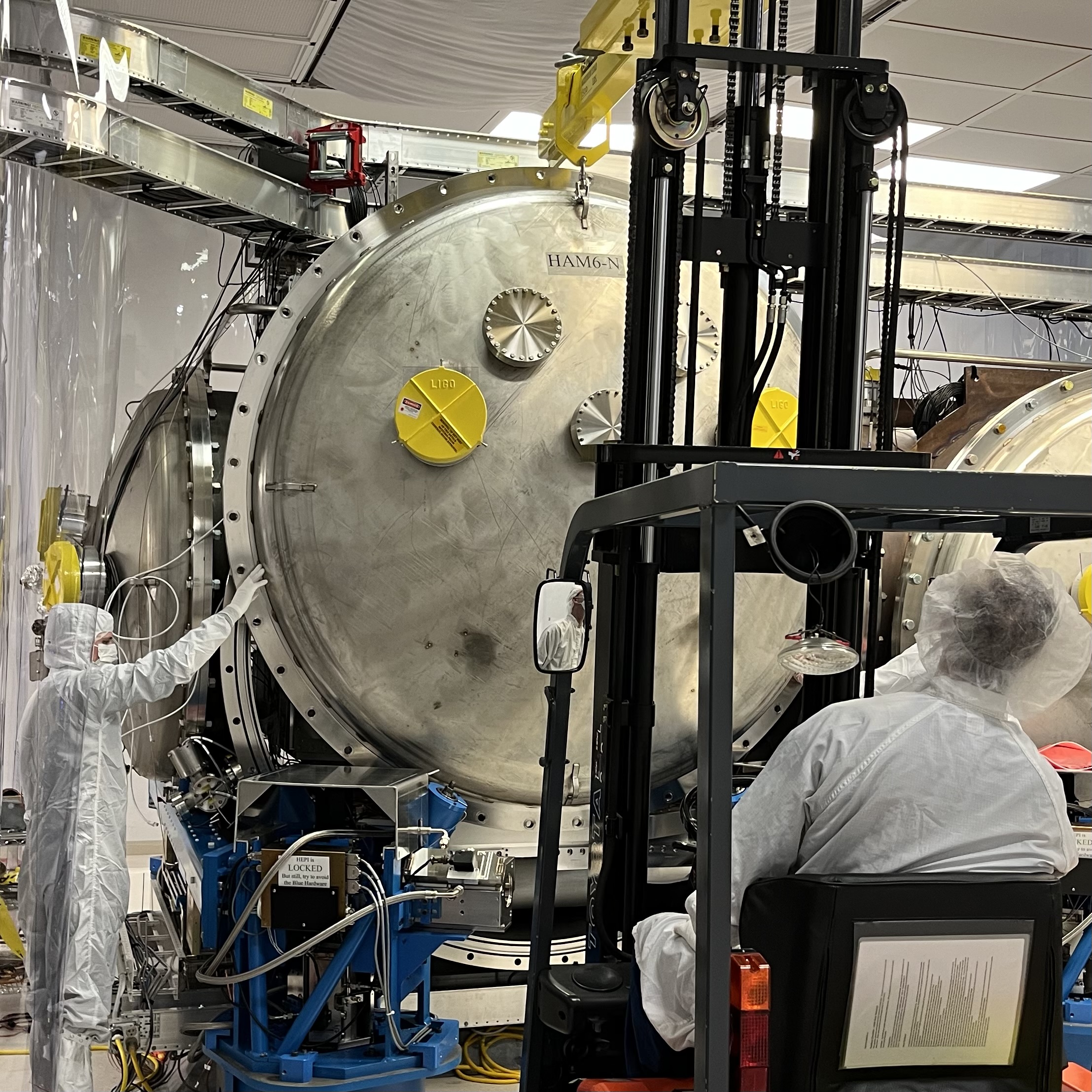
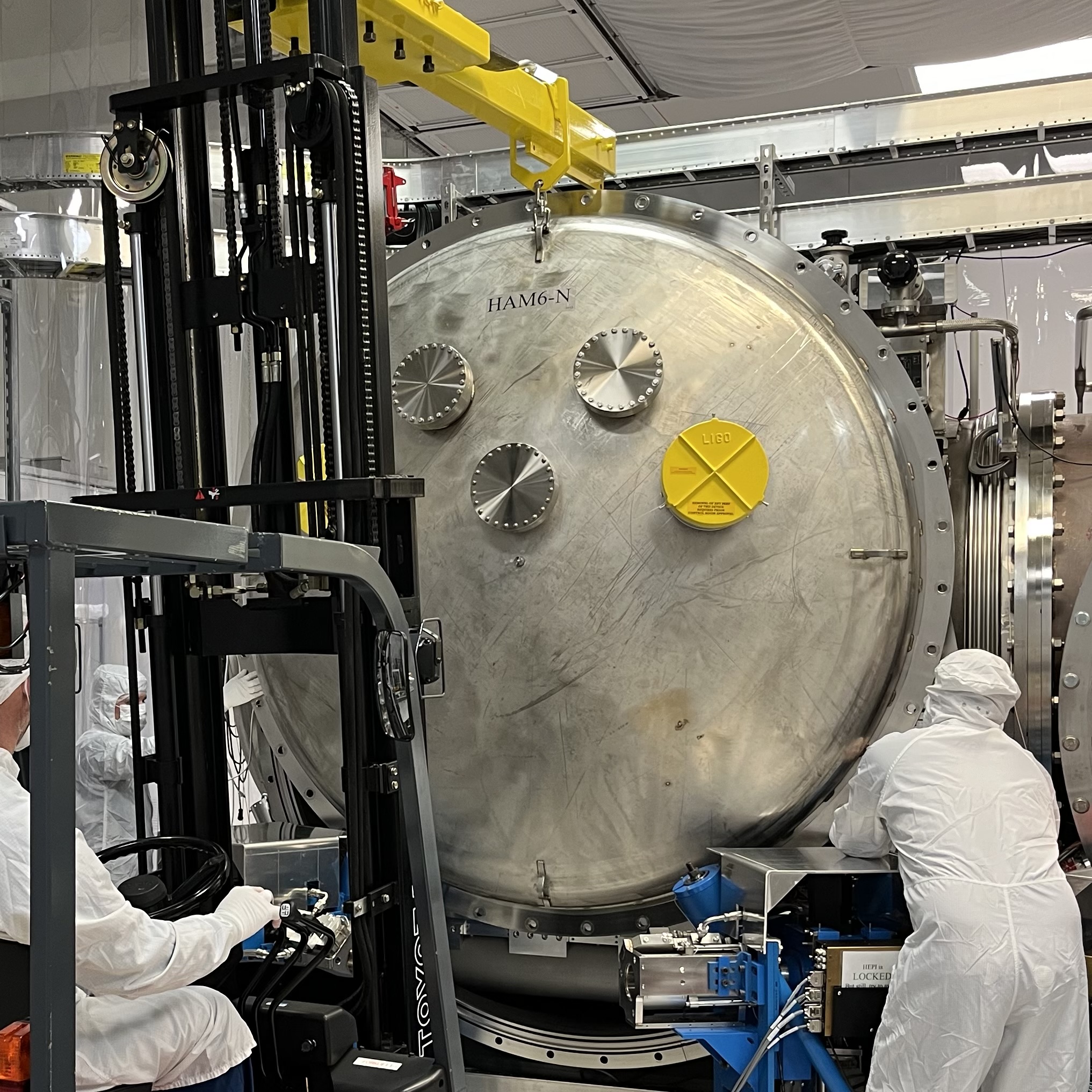
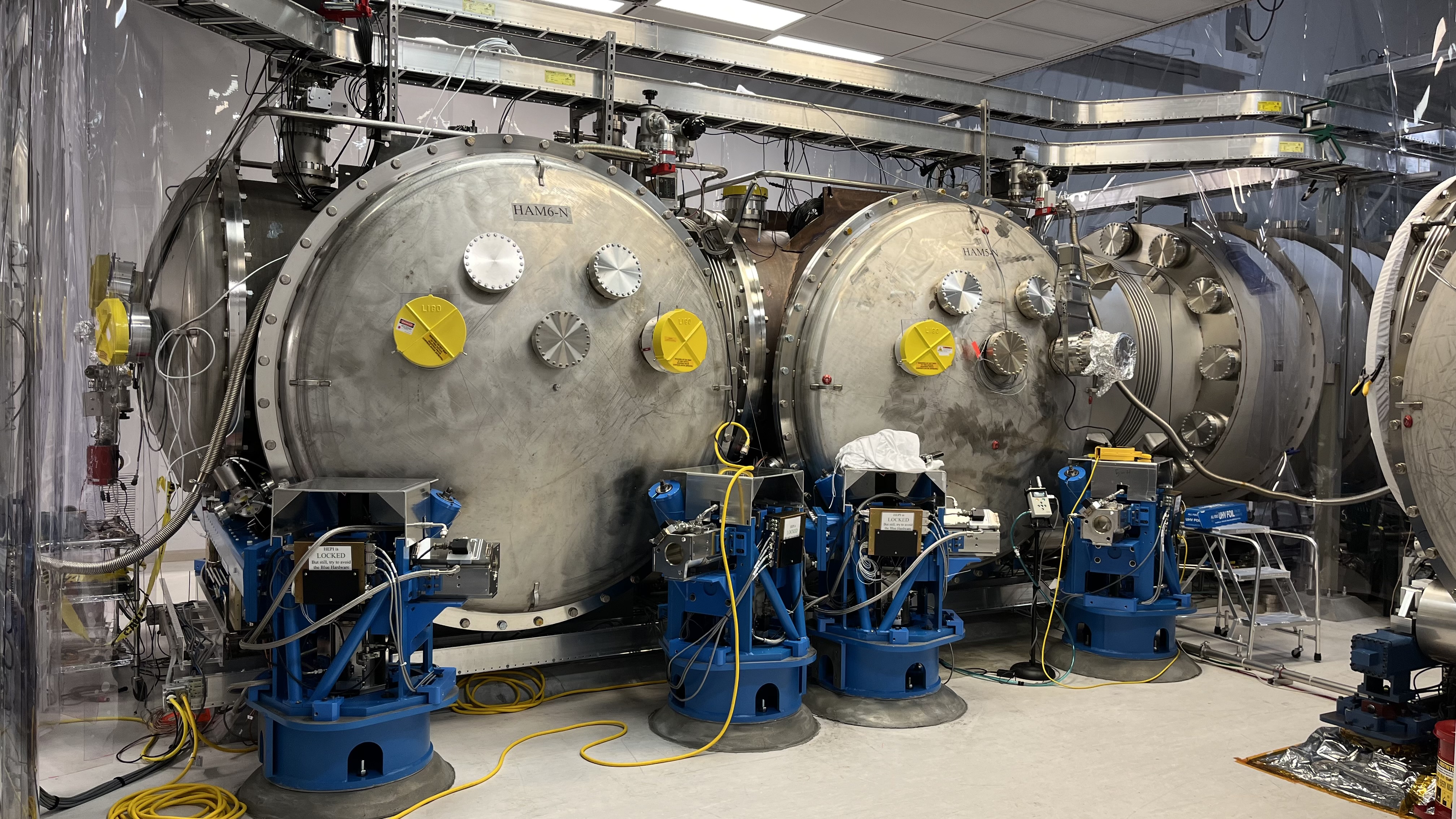
Tagging EPO for Door install pics.
TITLE: 02/09 Day Shift: 16:00-00:00 UTC (08:00-16:00 PST), all times posted in UTC
STATE of H1: Planned Engineering
INCOMING OPERATOR: None
SHIFT SUMMARY:
Big activity today was getting HAM6 closed up & preparing to pump the Corner Station (HAM7 still has doors off & additionally, the Relay Tube is also not installed.)
LOG:
Continued from previous ALOG75772
Replaced Endevco Accelerometer Power Conditioner with LIGO Accelerometer Power Conditioner. WP11653
S2300061 installed, the lone signal was installed and the chassis powered up the chassis.
I coordinated with Dave to power down the IO chassis. MX IO chassis is powered directly by a Sorensen, so we piggy backed our pigtail on this power connection.
This is the last accelerometer chassis to be installed and powered up.
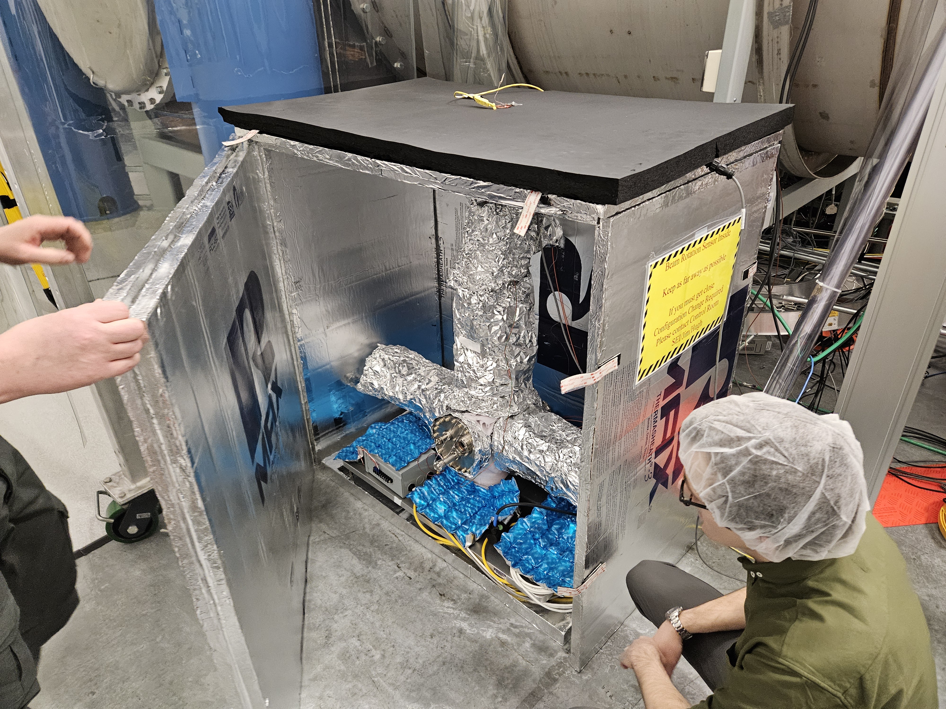
We successfully balanced the BRS with the remote mass adjuster for the first time this morning. The process was relatively painless. We used a windows machine to drive the picomotor and a separate laptop to monitor the BRS readouts. The BRS is still equilibrating and will drift more into range over the next few days.
Total movement today: -60k steps
Coupling/decoupling move: 1.25k steps
Maximum: +- 140k steps
Be careful: +-100k steps
Log:
-2.5k steps
-2.5k steps
+1.25k steps
-1.25k steps
-2.5k steps
+1.25k steps
-1.25k steps
-10k steps
+1.25k steps
-1.25k steps
-10k steps
+1.25k steps
-1.25k steps
-5k steps
+1.25k steps
-1.25k steps
-2.5k steps
+1.25k steps
-1.25k steps
-2.5k steps
+1.25k steps
-1.25k steps
-5k steps
+1.25k steps
-1.25k steps
-10k steps
+1.25k steps
-1.25k steps
-2k steps
+1.25k steps
-1.25k steps
-1.25k steps
+1.25k steps
-1.25k steps
-2.5k steps
+1.25k steps
-1.25k steps
-2.5k steps
+1.25k steps
Finally adding the pictures to this alog.
And a link to the Google doc for making the BRS changes.
https://docs.google.com/document/d/1XBH-TVwQ3JC8rjLGXUg-LDZKzHxaTuKBC3_-B_fWWAk/edit#heading=h.7b9gxgqfvsr0
Marc, Erik, Corey, Dave:
I have powered down h1pemmx in preparation for the IO Chassis power down, needed as part of Marc's accelerometer work.
Models back up and running at 15:06
WP 11635
The high voltage bypass on HAM6 and HAM7 have been removed in preparation for the corner pump down.
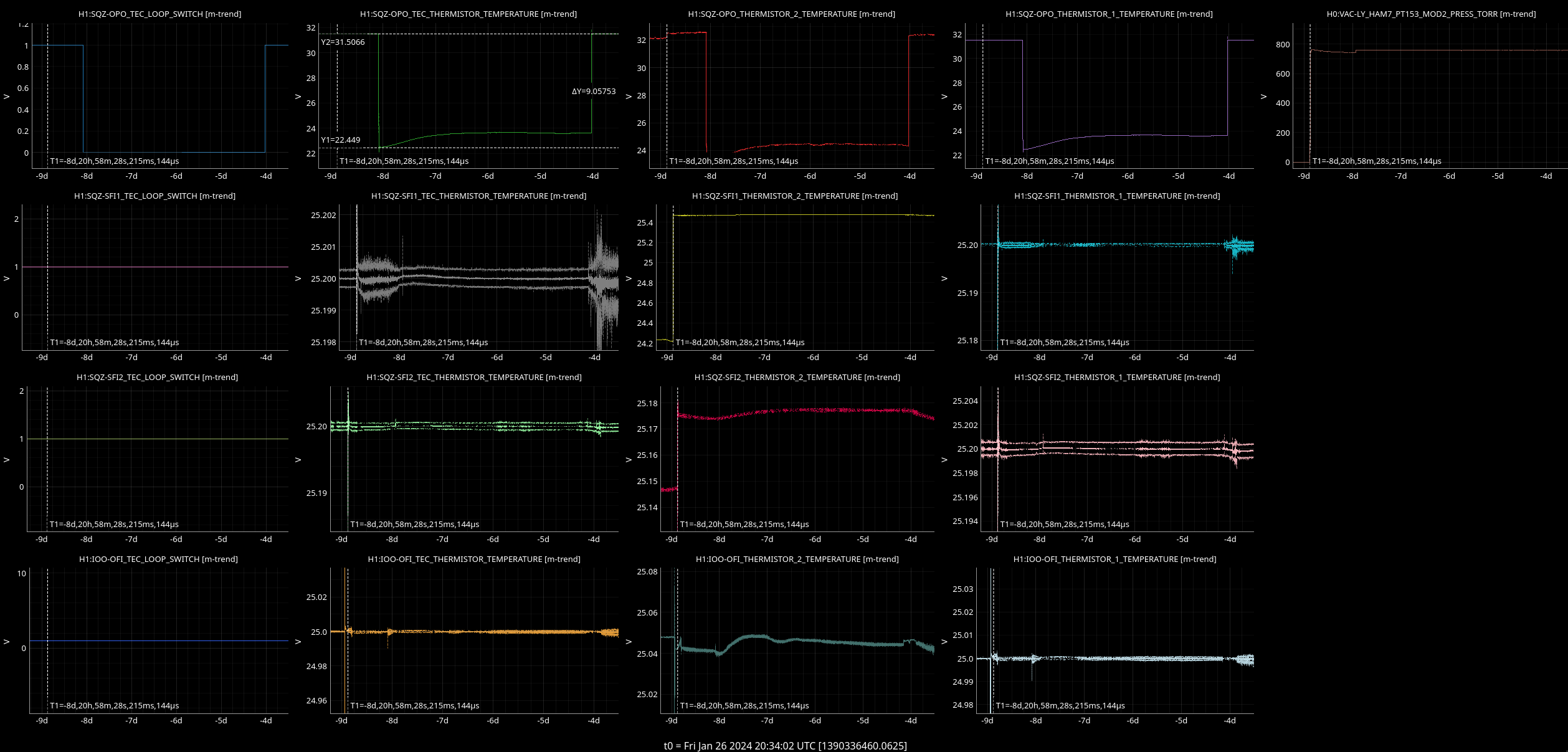
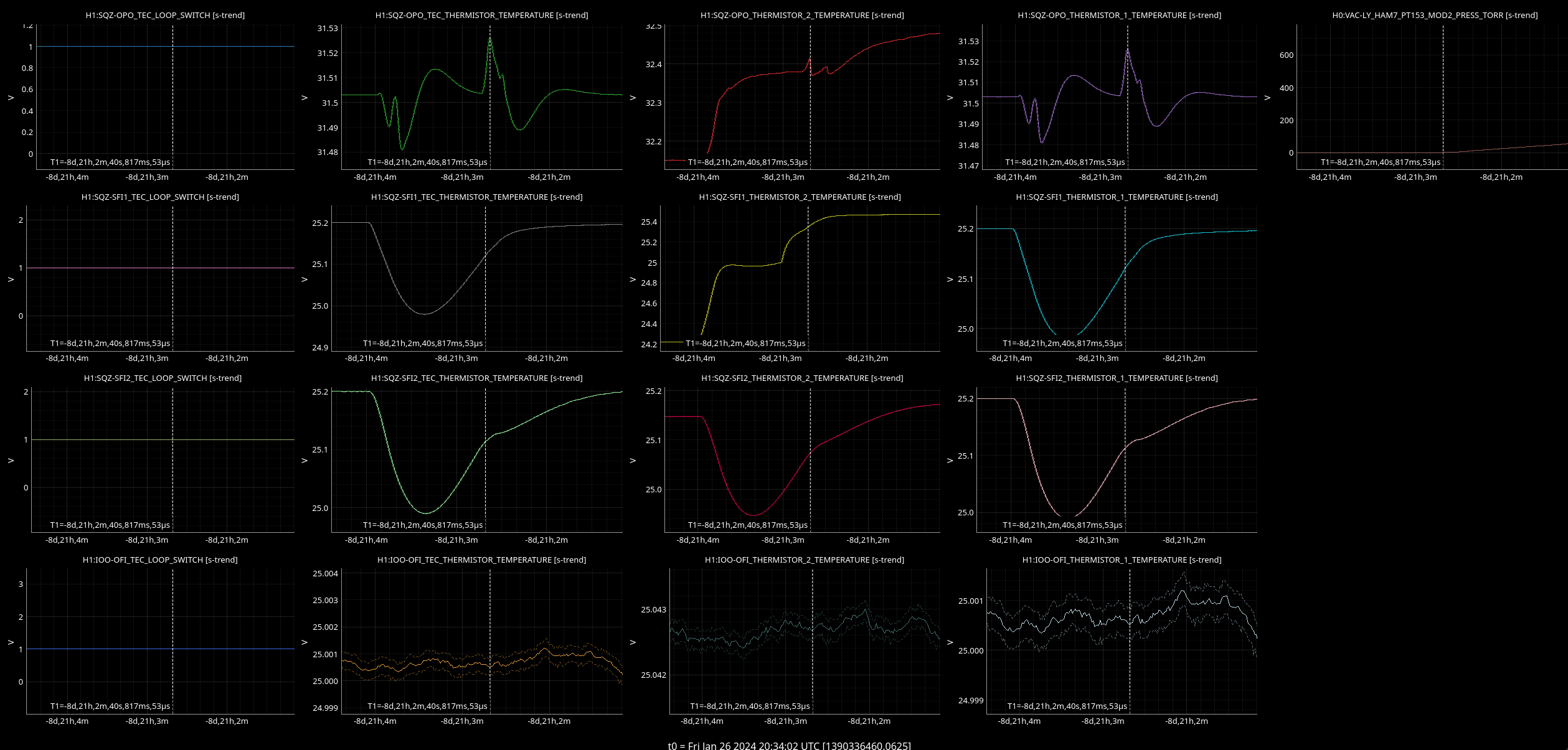
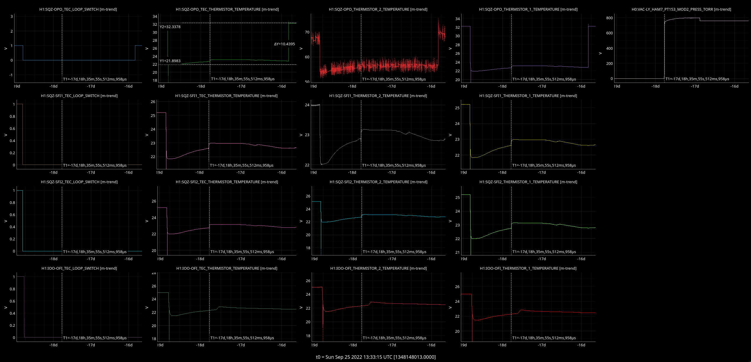
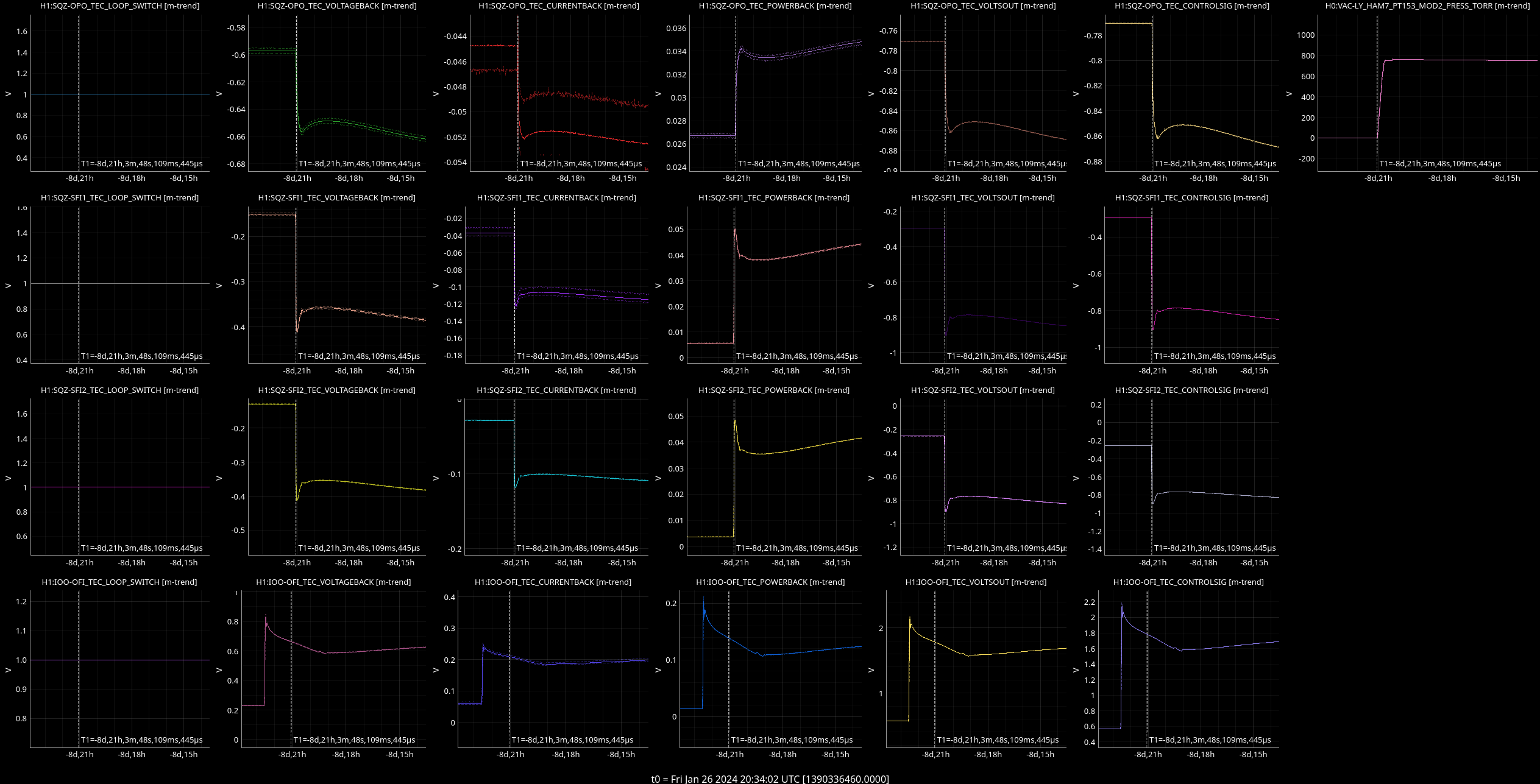
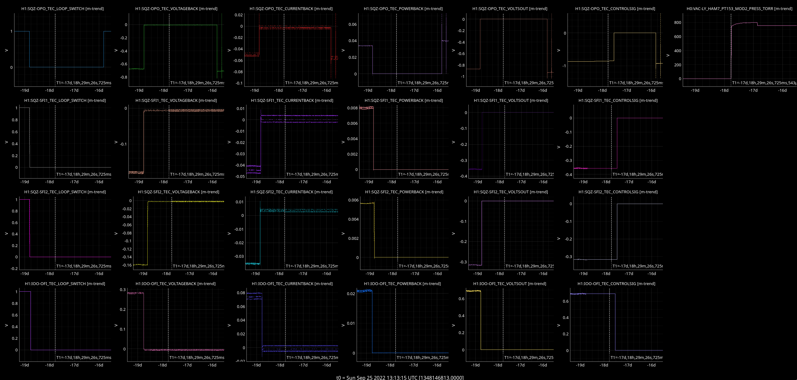
The purpose of this investigation is to find out whether or not the SQZ TEC servos needs to be switched off during venting (and then possibly to update M1300464).
Attached are pictures of sections in which all servos were switched off and once where all were on during venting.
The area between -19.5d and -15.5d from t0=Sun Sep 25 2022 13:13:15 UTC was selected for all servos are off and -11.5d to +1.5d from t0= Fri Jan 26 2024 20:34:02 UTC for all servos are on.
The images are named as follows:
The pictures are structured as followed:
| H1:SQZ-XXX_TEC_LOOP_SWITCH | H1:SQZ-XXX_TEC_THERMISTOR_TEMPERATURE | H1:SQZ-XXX_TEC_THERMISTOR_2_TEMPERATURE | H1:SQZ-XXX_TEC_THERMISTOR_1_TEMPERATURE | ||
| XXX = OPO | H1:SQZ-OPO_TEC_LOOP_SWITCH | H1:SQZ-OPO_TEC_THERMISTOR_TEMPERATURE | H1:SQZ-OPO_TEC_THERMISTOR_TEMPERATURE | H1:SQZ-OPO_TEC_THERMISTOR_TEMPERATURE | H0:VAC-LY_HAM7_PT153_MOD2_PRESS_TORR |
| XXX = SFI1 | |||||
| XXX = SFI2 | |||||
| XXX = OFI |
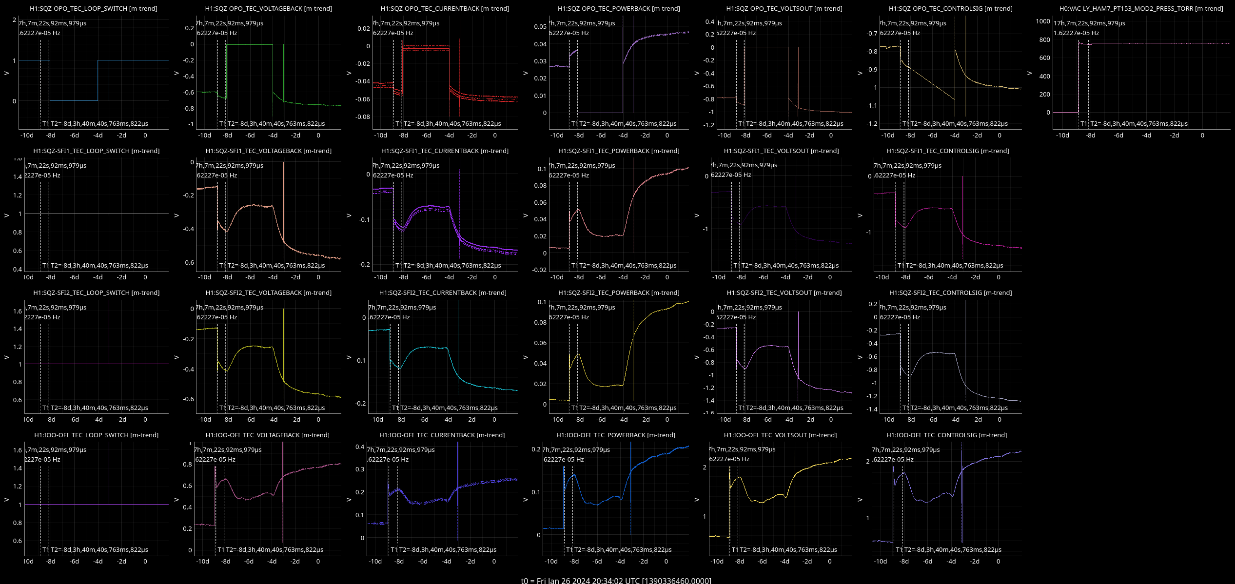
| H1:SQZ-XXX_TEC_LOOP_SWITCH | H1:SQZ-XXX_TEC_VOLTAGEBACK | H1:SQZ-XXX_TEC_CURRENTBACK | H1:SQZ-XXX_TEC_POWERBACK | H1:SQZ-XXX_TEC_VOLTSOUT | H1:SQZ-XXX_TEC_CONTROLSIG | ||
| XXX = OPO | H0:VAC-LY_HAM7_PT153_MOD2_PRESS_TORR | ||||||
| XXX = SFI1 | |||||||
| XXX = SFI2 | |||||||
| XXX = OFI |
Temperature does not change during venting, which means from this point of view it does not need to be switched off.
Whereas the readback senses venting. Most have only minimal changes in voltage of max 0.2V but a few have larger changes:
| Servo on | Servo off | |Servo on - Servo off| | ||
| H1:SQZ-OPO_TEC_VOLTAGEBACK [V] | 0.1 | 0.7 | 0.6 | Servo on < Servo off |
| H1:SQZ-OPO_TEC_VOLTSOUT [V] | 0.1 | 0.85 | 0.7 | Servo on < Servo off |
| H1:SQZ-SFI1_TEC_VOLTSOUT [V] | 0.6 | 0.35 | 0.25 | Servo on > Servo off |
| H1:SQZ-SFI2_TEC_VOLTSOUT [V] | 0.7 | 0.3 | 0.4 | Servo on > Servo off |
| H1:SQZ-OFI_TEC_VOLTAGEBACK [V] | 0.6 | 0.3 | 0.3 | Servo on > Servo off |
| H1:SQZ-OFI_TEC_VOLTSOUT [V] | 1.6 | 0.7 | 0.9 | Servo on > Servo off |
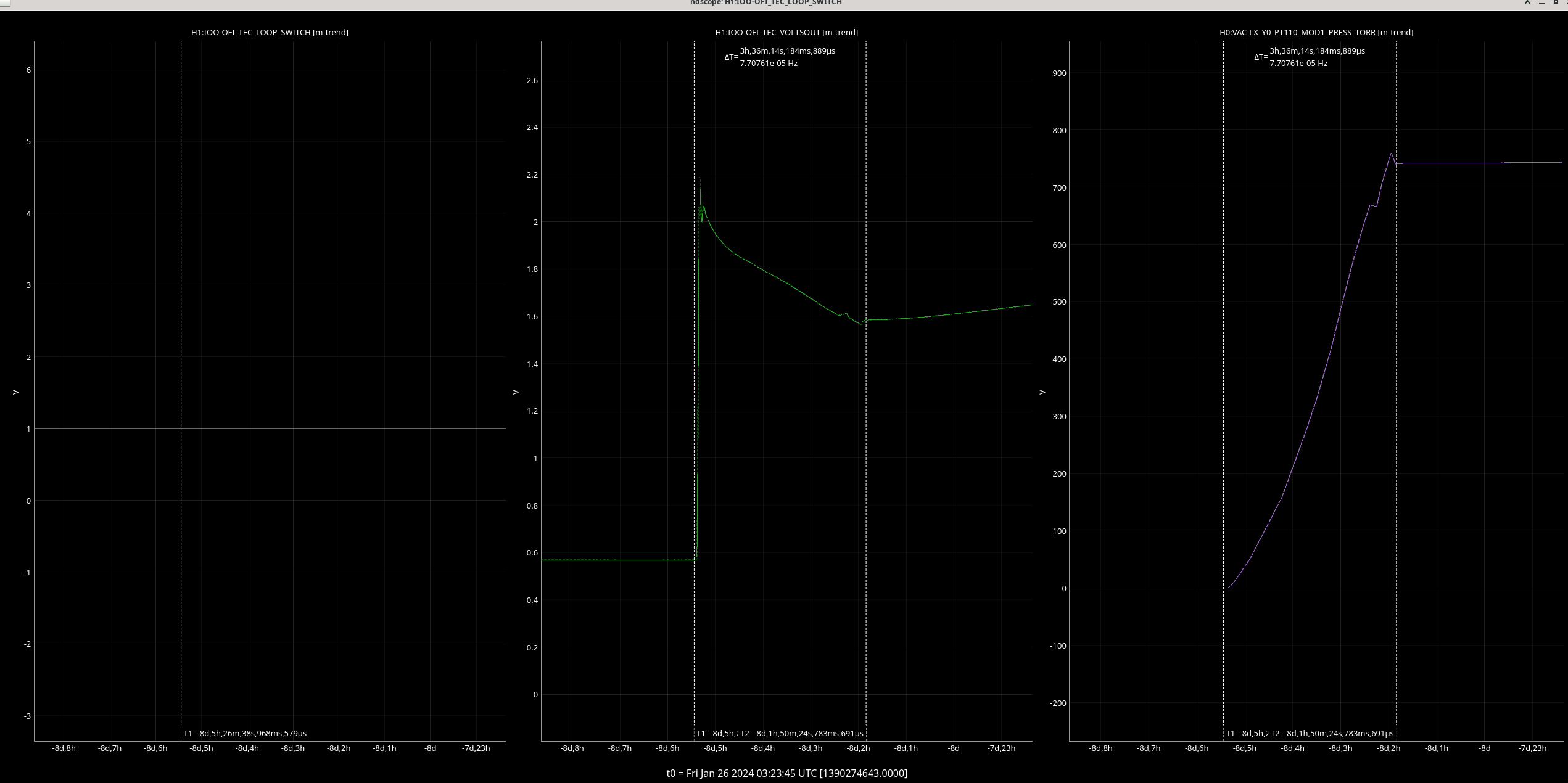
Attached is a plot of OFI with the pressure analysis as the venting in this chamber was earlier.
Fri Feb 09 10:06:42 2024 INFO: Fill completed in 6min 38secs
J. Oberling, R. Crouch
Update on FARO progress so far.
Monday, 2/5/2024
On Monday we tried adding a monument to the existing alignment routine, primarily to see how it worked; we used the same alignment from alog 75706, the one where we had changed PSI-1 and PSI-2 to points but kept BTVE-1 and PSI-6 as spheres (the final 2 pictures from the alog). We used the magnetic nest that we had placed in line with height mark 903 and checked with an autolevel that it was still in line with the height mark (done before the LVEA went Laser Hazard for HAM6 work, nest alignment to height mark was good as found). The FARO gave us X and Y coordinates for the nest, and we used those to convert the local Z coordinate for 903 into a global Z as described in alog 75706. The listed local Z for 903 is -79.9mm (from T1100187), which translates to a global Z for the nest of -79.7mm using the following:
ZG = ZL + (XL * 0.0006195) + (YL * -0.0000125) = -79.9 + (1082.3 * 0.0006195) + (37455.6 * -0.0000125) = -79.7mm [1]
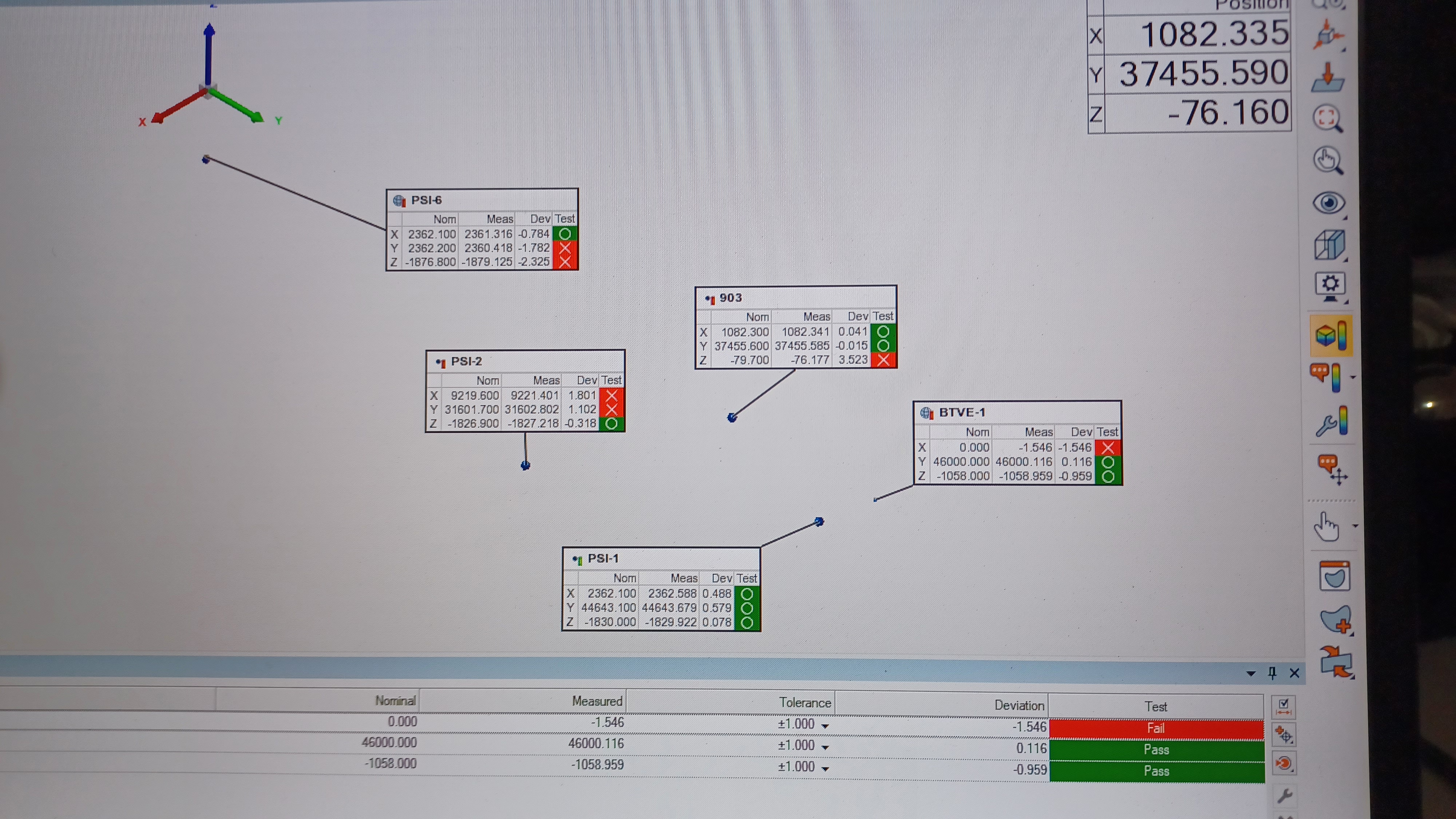
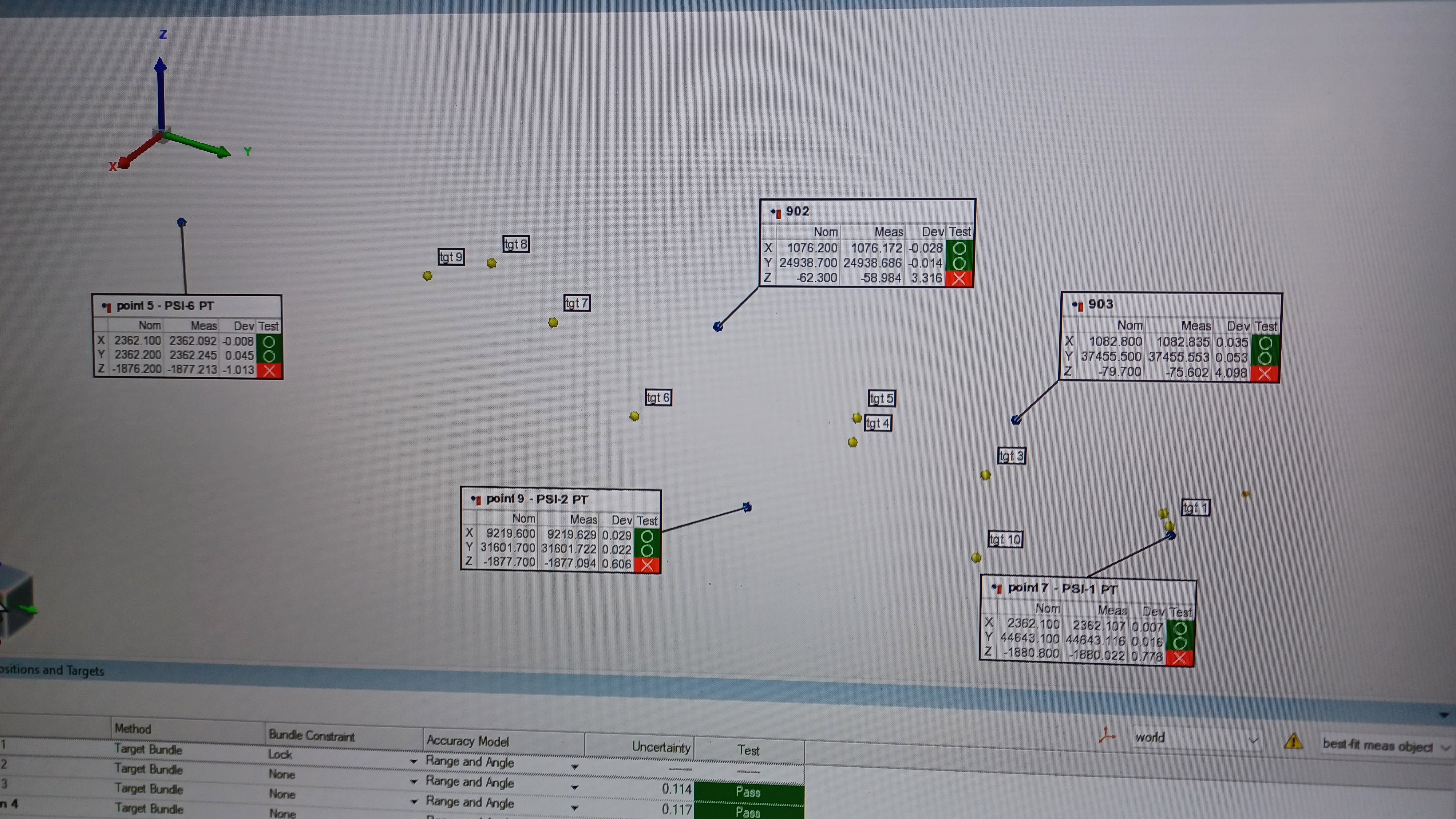
Including the mark in the alignment routine was very straightforward: Open the alignment routine, right click in the window listing the objects used in the alignment and select Add Object, and select the desired point from the drop-down menu. The results of adding this point to the existing alignment routine are shown in the first 2 pictures. As can be seen some got worse and some got better. While it's tempting to say the Build/Inspect results are great, there is one caveat. We checked PSI-6 in the same way we performed the differential height survey between BTVE-1 and PSI-6 in alog 75669 (SMR on the CPN ~1 foot in front of the monument on the vinyl floor, but in line with the X coordinate; we know this isn't exact, but it gives a ballpark) and that found PSI-6 to be -1.1mm from its nominal Z axis coordinate. Another interesting note, notice the measured Z for 903 in the first picture (2nd column on the annotation). When incorporating 903 into the alignment routine, the best the FARO can do is get within 3.5mm of the nominal Z axis coordinate; when 903 is out of the alignment routine, the FARO thinks it's ~4.2mm above its nominal Z axis coordinate. That's... not so good, and an indication of maybe a larger discrepancy in Z coordinates than we initially thought.
Wednesday, 2/7/2024
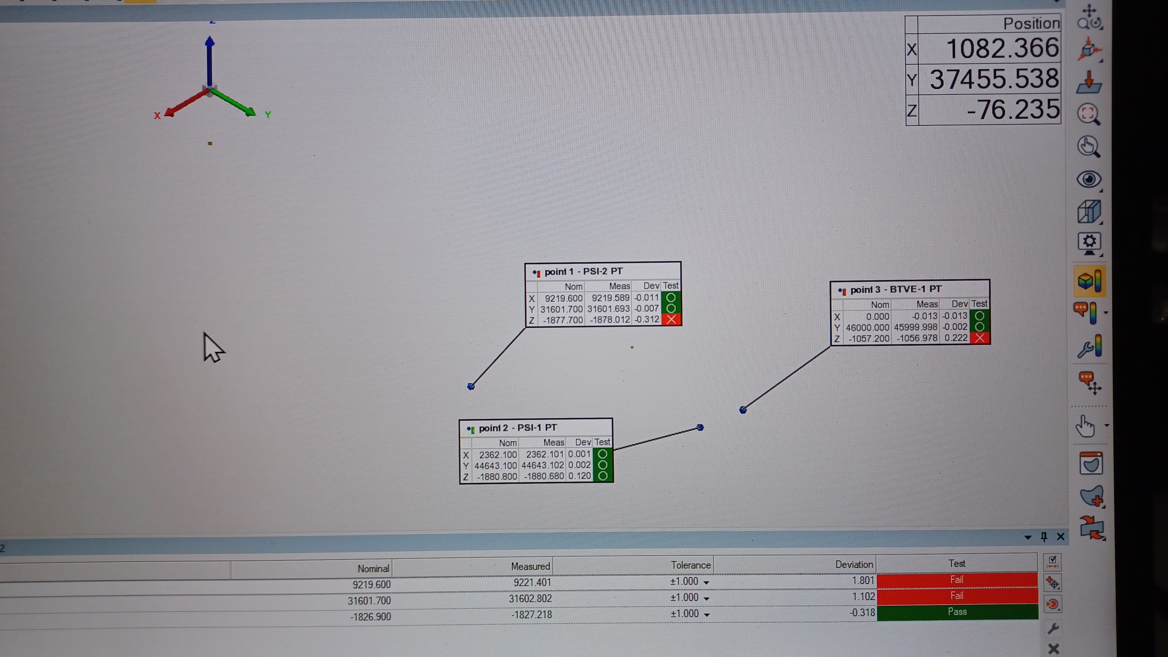
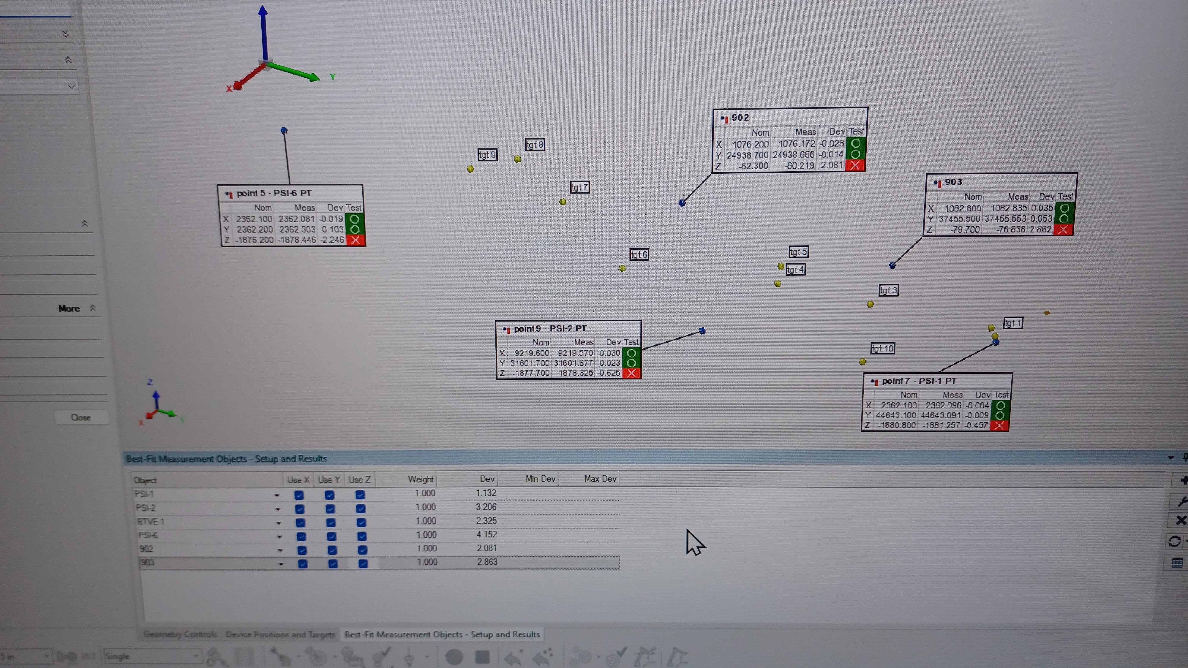
We did the alignment test noted at the end of alog 75706; use a sphere for BTVE-1 and points for PSI-1, PSI-2, and PSI-6. We used BTVE-1, PSI-1, and PSI-2 to perform an initial alignment, then moved the FARO to a spot with direct line of sight to PSI-6. We then probed PSI-6 as a point instead of a sphere and added it to the alignment routine. The third picture shows the results of the alignment routine. We did a Build/Inspect to PSI-6, since we were in a location with direct line of sight, and then moved the FARO back out to the West Bay to do Build/Inspect for PSI-1 and PSI-2; we wanted a line of sight to height mark 902, but this put us out of line of sight to BTVE-1 so we did not do a Build/Inspect to it. The Build/Inspect results are shown in the fourth picture. That is also not so great, and one of the worse Z axis alignments we've seen. This was unexpected given the variations we've seen when using the sphere fit rod.
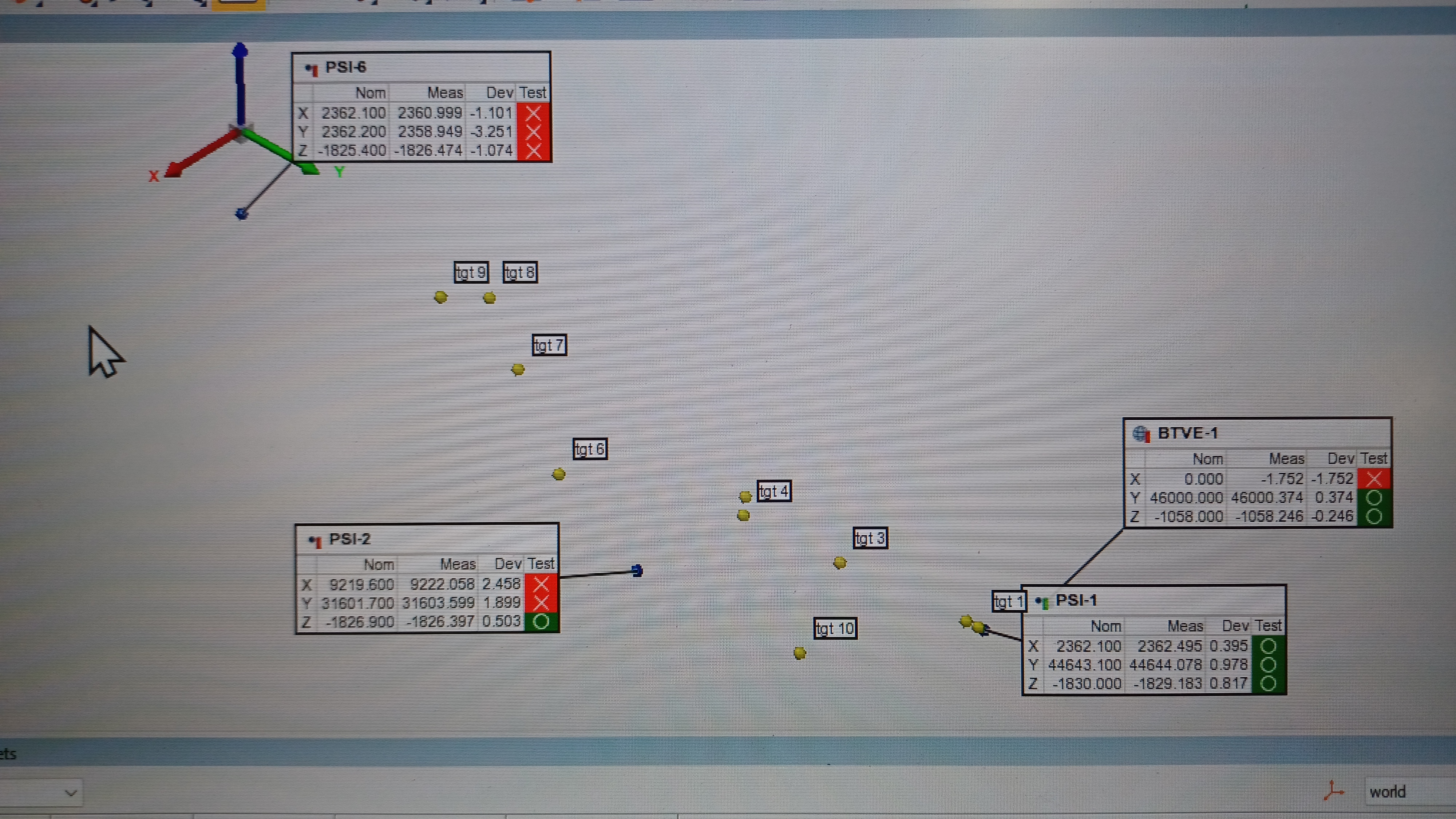
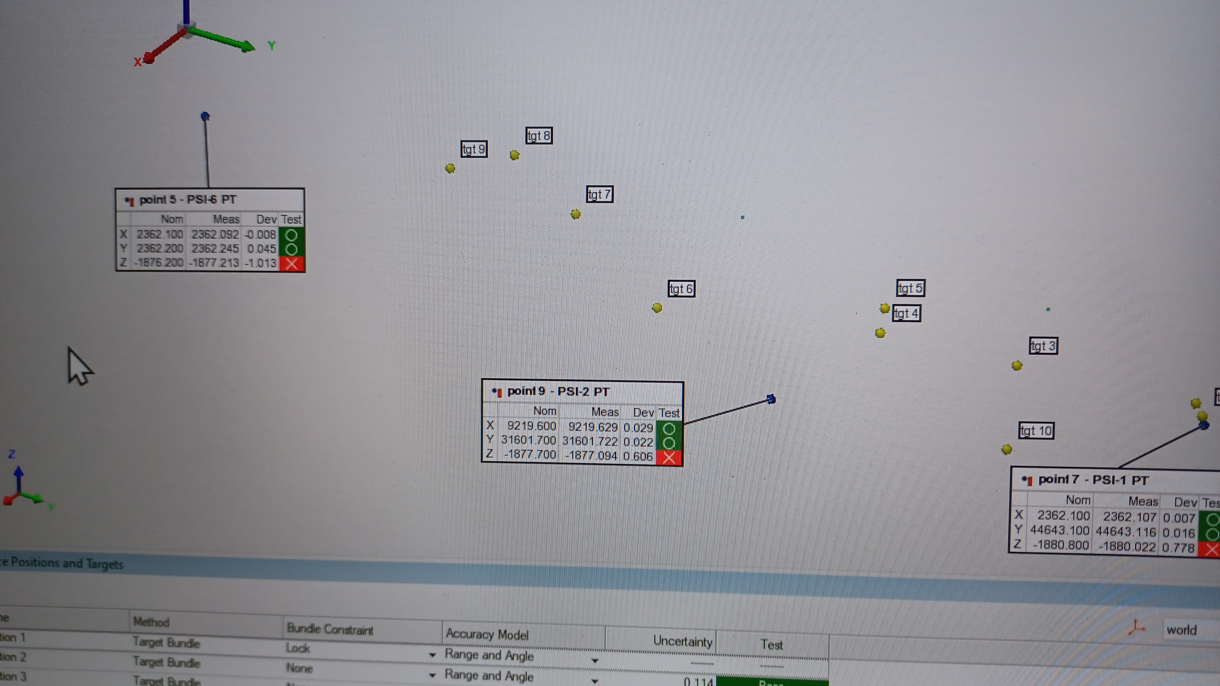
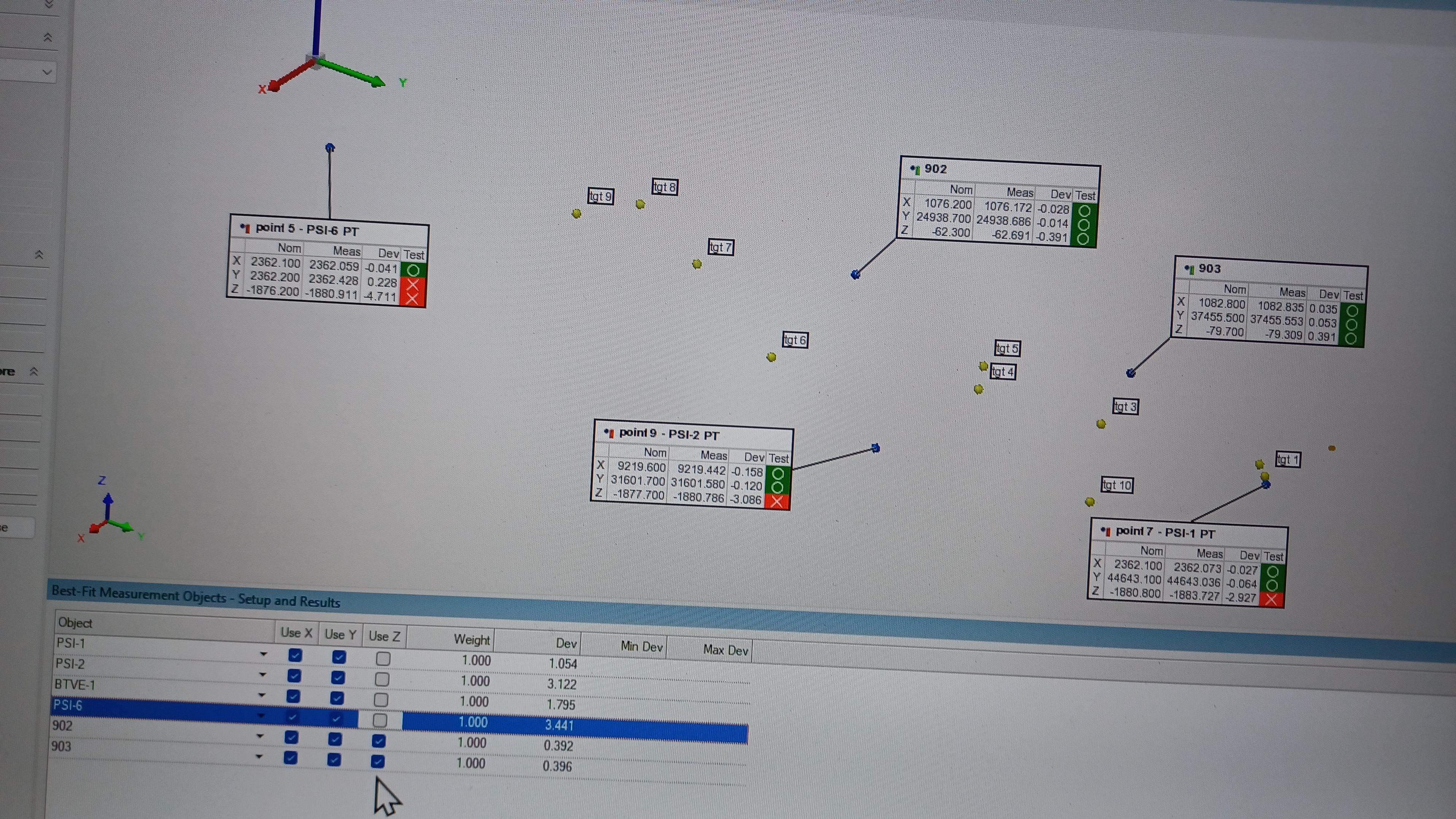
Since we had line of sight to height marks 902 and 903 we used the magnetic nests that we had placed on them to probe them against their nominal coordinates (global Z for 902 was calculated in the same way as we did 903); at this time the LVEA was in Laser Hazard so we were unable to use an autolevel to confirm the magentic nests were still in line with the height marks (903 had been checked on Monday so was likely still good; 902 was last checked roughly a week ago so could have shifted, will check it now that the LVEA is Laser Safe). The results are shown in the fifth picture. There is something fishy here, as the FARO thinks both height marks are higher than our listed coordinates would indicate, by 3 to 4 mm, again indicating that we have some discrepancy between the BTVE/PSI Z axis coordinates and those of the height marks. This was also apparent when we attempted to include both height marks in our Z axis alignment routine. The sixth picture shows the Build/Inspect results if the height marks are included into the Z axis alignment routine with the BTVE/PSI monuments, and the seventh picture shows the Build/Inspect results with the alignment routine considering only the height marks (the check marks next to Use X and Use Y make no difference here, as this portion of the alignment routine has been constrained to only align the Z axis). Including the height marks with the BTVE/PSI monuments results in a bad alignment, especially for PSI-6; the FARO still cannot get a good alignment to 902 and 903. Using only the height marks gets a good alignment to the height marks, but drags the PSI monument way out. This is a further indication of some discrepancy between our BTVE/PSI monuments and our height marks.
Thursday, 2/8/2024
Seeing this potential discrepancy between our BTVE/PSI Z coordinates and our height marks, we set out to try to see where this comes from. Recall, per T1100187 the height marks were laid out in the local LVEA coordinate system, all relative to WBSC2 [0,0,0] (which is the origin of the site coordinate system, both the site global and the LVEA local). The first set of height marks were set using the chamber-side door flange scribe lines; there are 2 scribes on each door flange (one at the 9 o'clock and one at 3 o'clock), for a total of 8 scribe lines per chamber. The 8 scribe lines for WBSC2 were averaged together to produce the Z axis origin, and the height marks were set relative to this. The initial chamber placement was done using the BTVE/PSI monuments, thereby linking them to the height marks. Knowing this, we again used the FARO as an autolevel to perform a differential height measurement between BTVE-1 and height marks 902 and 903. We set the FARO in a location with line of sight to BTVE-1, PSI-1, PSI-2, and both height marks. It was oriented to local gravity and we used the Hubbs CPN (with its 2" vertical offset) to measure a Z coordinate for BTVE-1, PSI-1, and PSI-2, corrected in the -Z direction by 50.8mm to account for the vertical offset of the CPN. These Z coordinates are relative to FARO's initial coordinate system, but since we're doing a differential height survey this doesn't matter. We then did the same measurement with the height marks, and calculated a measured deltaZ between our height marks (and a repeat of PSI-1 and PSI-2) and BTVE-1. Results, all units in millimeters:
Interesting here is that our deltaZ for PSI-1 and PSI-2 is different than our last measurement in alog 75669, both by +0.2mm. This is a very small difference so not very worrying, and is likely caused by how the CPN sits in the BTVE punch (since the punch is not directly on the top of the domed monument, the CPN does have a slight wiggle to it; we tested this by wiggling the CPN and watching the measured Z coordinate, it does move but by only a couple tenths of a mm). The deltaZ between marks 902 and 903 comes out at +16.9 mm w.r.t. 902; the theoretical difference is +17.2mm w.r.t. 902, so pretty close.
Moving on, we can convert our global Z for BTVE-1 into a local Z using the opposite direction cosines used above in [1] (from Section 2 of T0900340 XL = XG and YL = YG). This looks like:
ZL = ZG + (XG * -0.0006195) + (YG * 0.0000125) = -1057.2 + (0.0 * -0.0006195) + (46000.0 * 0.0000125) = -1056.6 mm [2]
With a local Z for BTVE-1 we can then calculate the theoretical deltaZ to height marks 902 and 903 and compare to our measured (all units in millimeters):
| Theoretical | Measured | Difference | |
| deltaZ902 | +993.9 | +997.4 | +3.5 |
| deltaZ903 | +976.7 | +980.5 | +3.8 |
So according to the FARO these 2 height marks are several mm higher than our listed coordinates indicate, at least w.r.t. BTVE-1. As a quick and dirty test we have line of sight to height mark 504, which sits on the north wall of the West Bay, near the main crane parking spot. We do not have a nest on this mark (would need to glue one, the walls aren't magnetic), but roughly holding the SMR center on the height mark we were able to get a ballpark Z and compare it to BTVE-1. This indicated that mark 504 is very approximately +2.9mm from where T1100187 says it is. Combined with the discrepancies measured for 902 and 903, this is worrying. Where is this coming from? Several possibilities come immediately to mind:
Our next step is to try to figure out the source of this discrepancy. The obvious way is to check WBSC2 Z=0 against the existing height marks to see how they register to each other using the 8 door flange scribe lines on WBSC2. This is much easier said than done, however. There is a lot of infrastructure blocking lines of sight, including beam tubes and other BSC chambers, electronics racks, TCS/HWS tables, HEPI piers, and cabling that was not present when WBSC2 Z=0 was established during site construction. So in reality our next step is to figure out how to figure out the source of this discrepancy. Stay tuned, more to come.
Ryan and I took a walk around WBSC2 this morning, and given the amount of items blocking line of sight we are currently looking into setting up a water tube level as suggested by Mike here. This would give us a way to register door flange scribes on opposite sides of the beam tubes. The thinking is we could use an autolevel, water tube level(s), and some scales to average the door flange scribes together and recreate the original Z=0; we could then use this to start checking the height marks in the LVEA (specifically the West Bay to start, I think, since that's where we're currently working and finding these apparent discrepancies).
Forgot to add to the above alog, on Thursday afternoon we also used the FARO in the last used alignment routine (BTVE-1 as a sphere, PSI-1, PSI-2, and PSI-6 as points) to probe the old brass floor monuments for Test Stand #2 as a possible means to test our alignment to the X and Y axes (yes, we don't like the Z axis alignment of this routine, but we're not testing Z here). Our X and Y alignment has looked very good in every iteration of this routine we have done, but to date we have only tested against the monuments we use to set the alignment; we would expect these to have a good alignment (hence our continued puzzlement with Z). But how well does this aligment work when tested against monuments not used to set the alignment? Enter the Test Stand monuments. D1100291 includes monument layouts for the mechanical test stands used during initial aLIGO install (used to pre-build and align the ISI+SUS "cartridges" before installation into a BSC chamber). These monuments are only registered to the test stand they are associated with, but we do have a monument representing [0,0]. The thinking here is we can probe the [0,0] monument (monument TS2-10, in this case), which then allows us to put the rest of the test stand monuments into our LVEA coordinate space. This gives us a theoretical X/Y location for the rest of the test stand monuments that we can then compare to where the FARO thinks they are. Data has been collected and is currently being processed, will post results once complete.
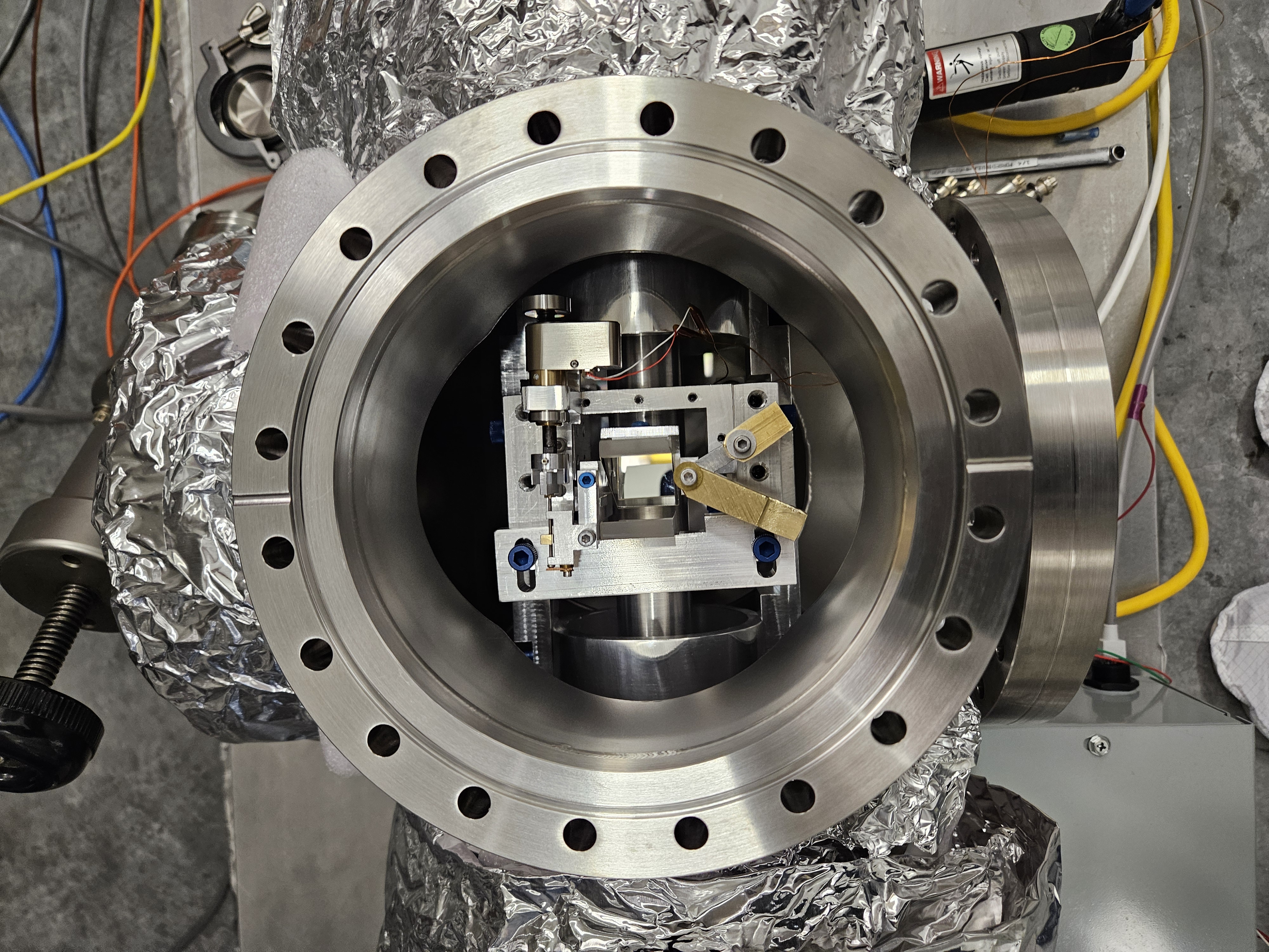
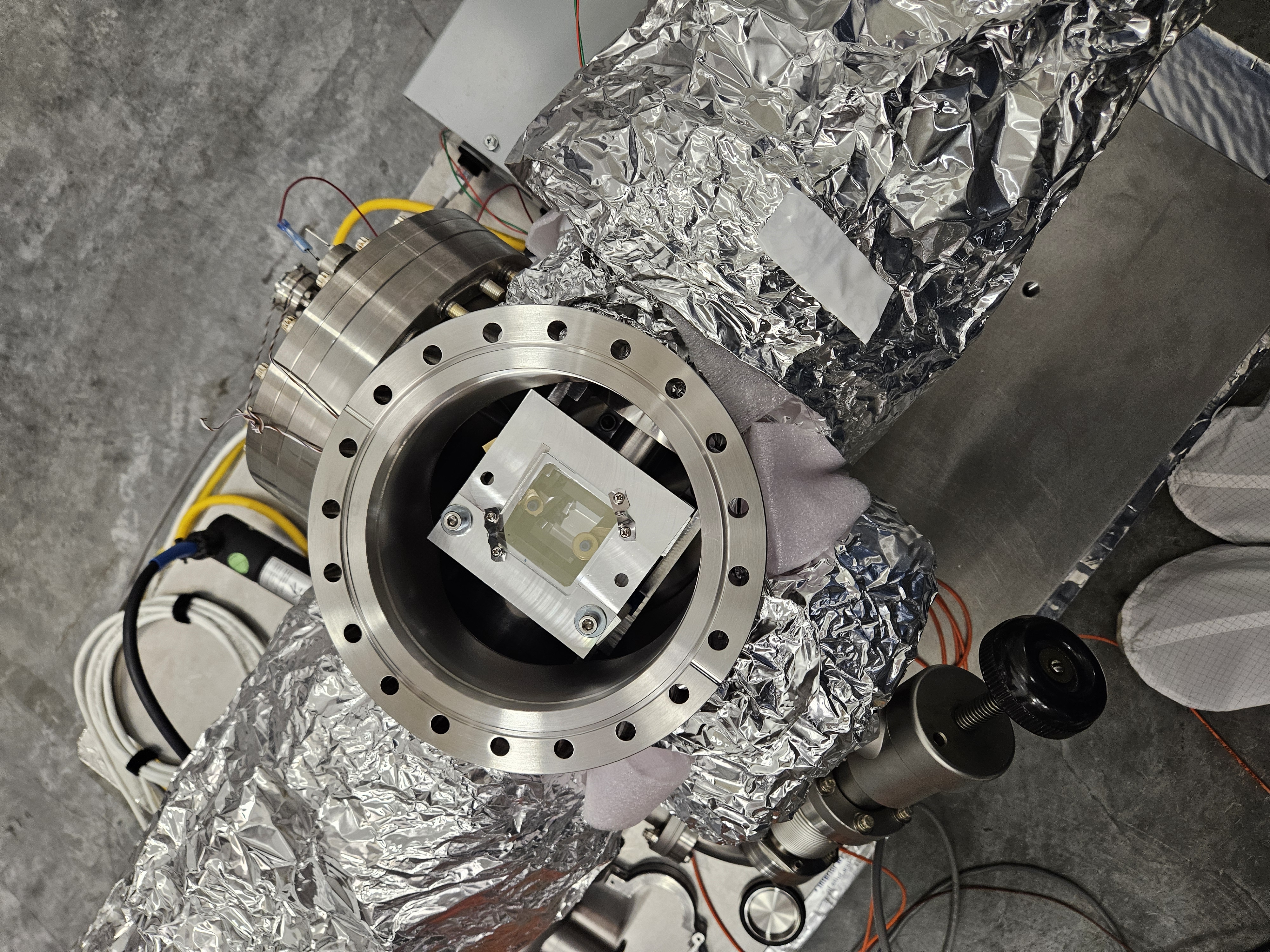
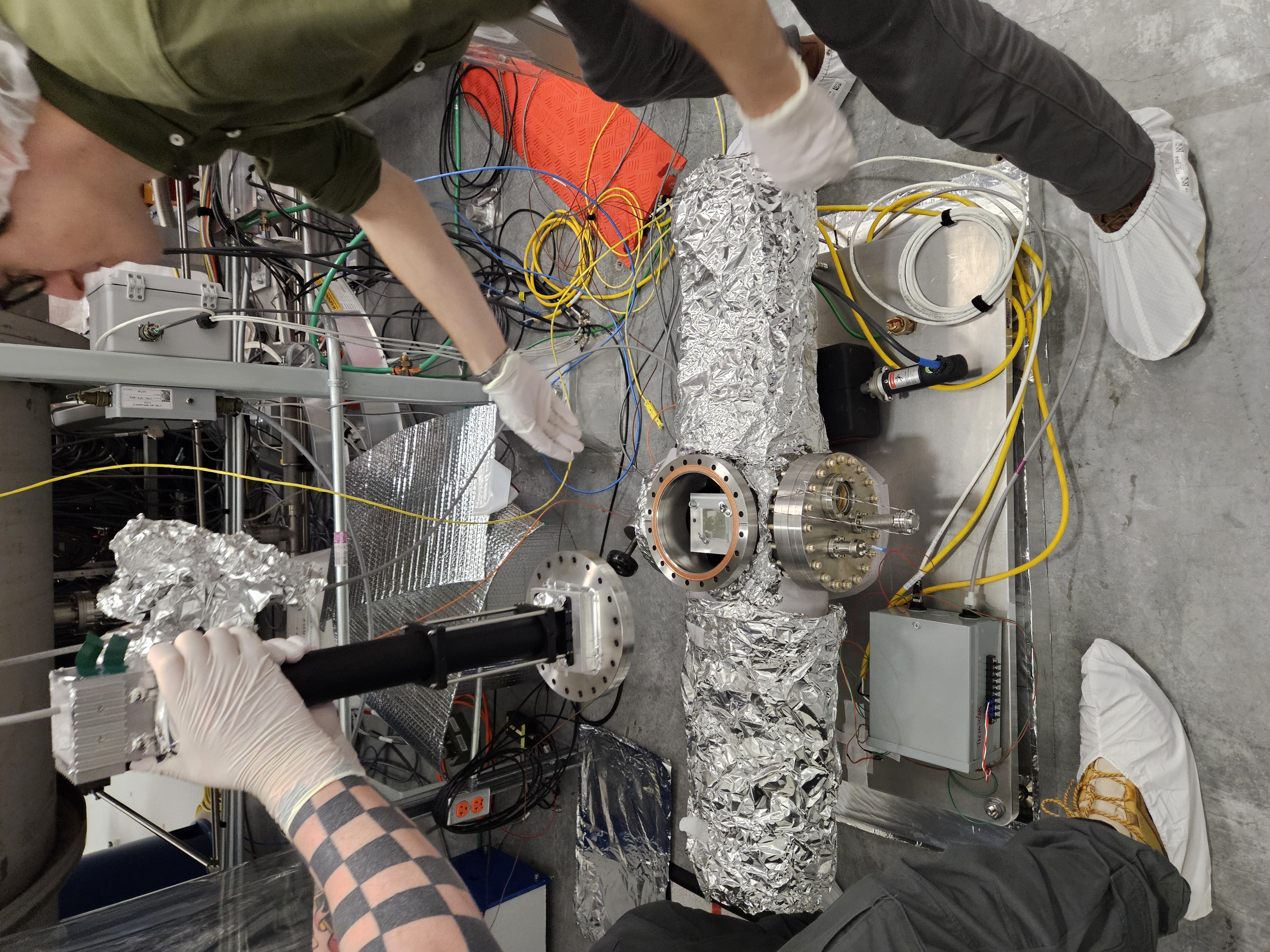
(Betsy, Keita, Rahul, Sheila
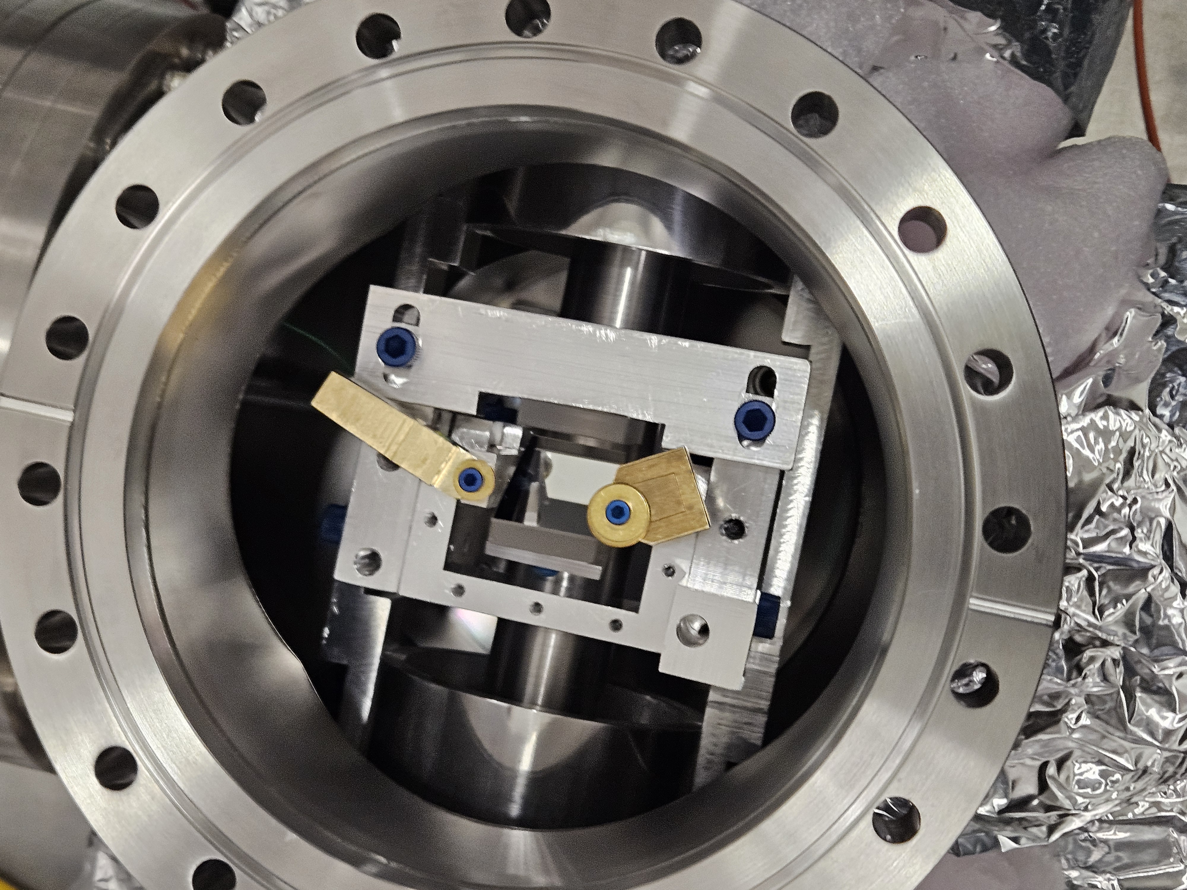
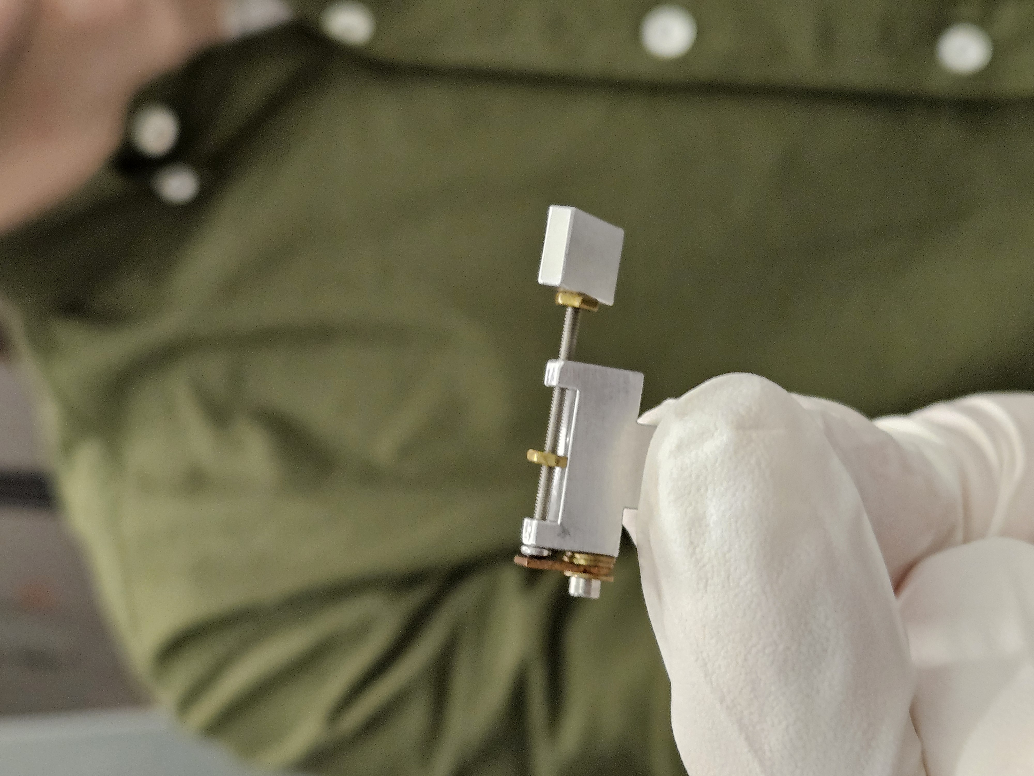
We finished installing the new square-hole OMC glass shround end panels this morning after a good round of cleaning.
Then we spent most of the day hunting for the OMC Trans Cam beam - we finally found it, aligned it to the viewport door simultor, and were able to launch Jim and Rahul for final SUS/SEI closeout.
We transitioned to Laser Safe (thanks TJ), Closed HAM6, 7 and the HAM5 mini port gatevalve.
A new contam control wafer was laid near the center of the table and cables, tools, interferences, were all checked. Most signoffs have been complete - Jim and SUS crew checking TFs now and expect to be cleared this eve. Jim has signed off, Rahul on now. He'll txt me any issues, so otherwise all good, doors to proceed.
Doors on HAM6 tomorrow morning followed by corner pump down ~Monday hopefully.
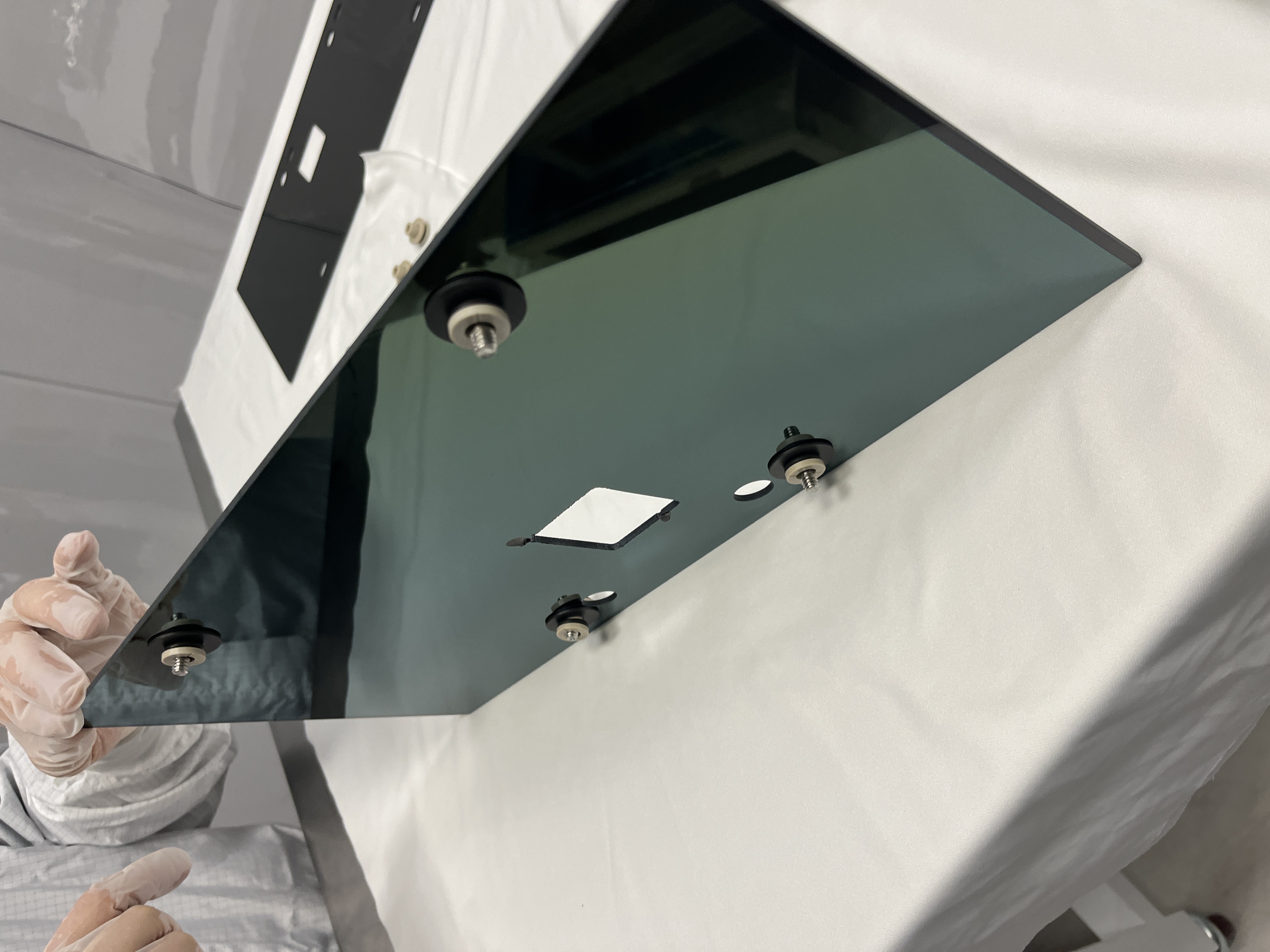
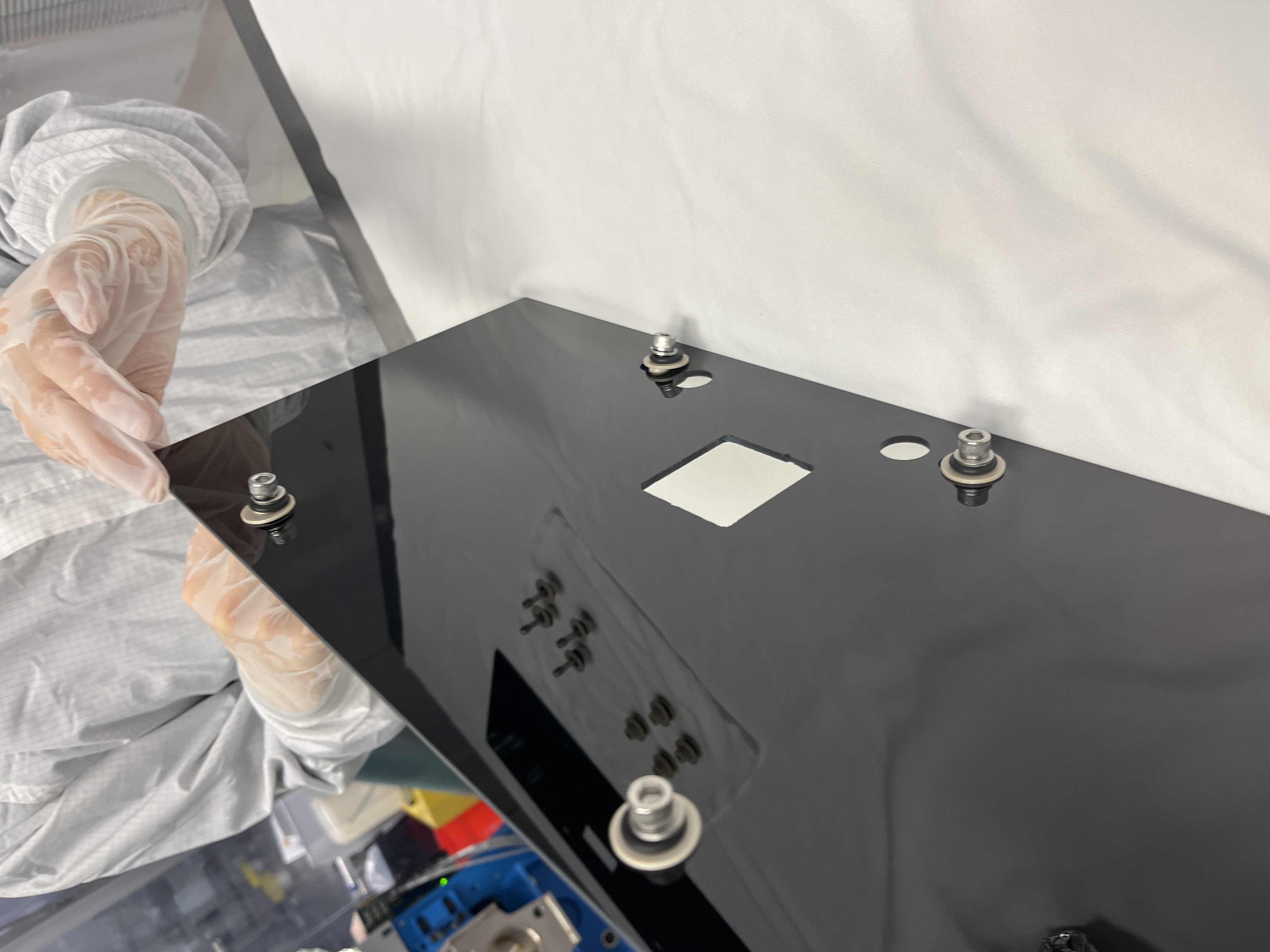
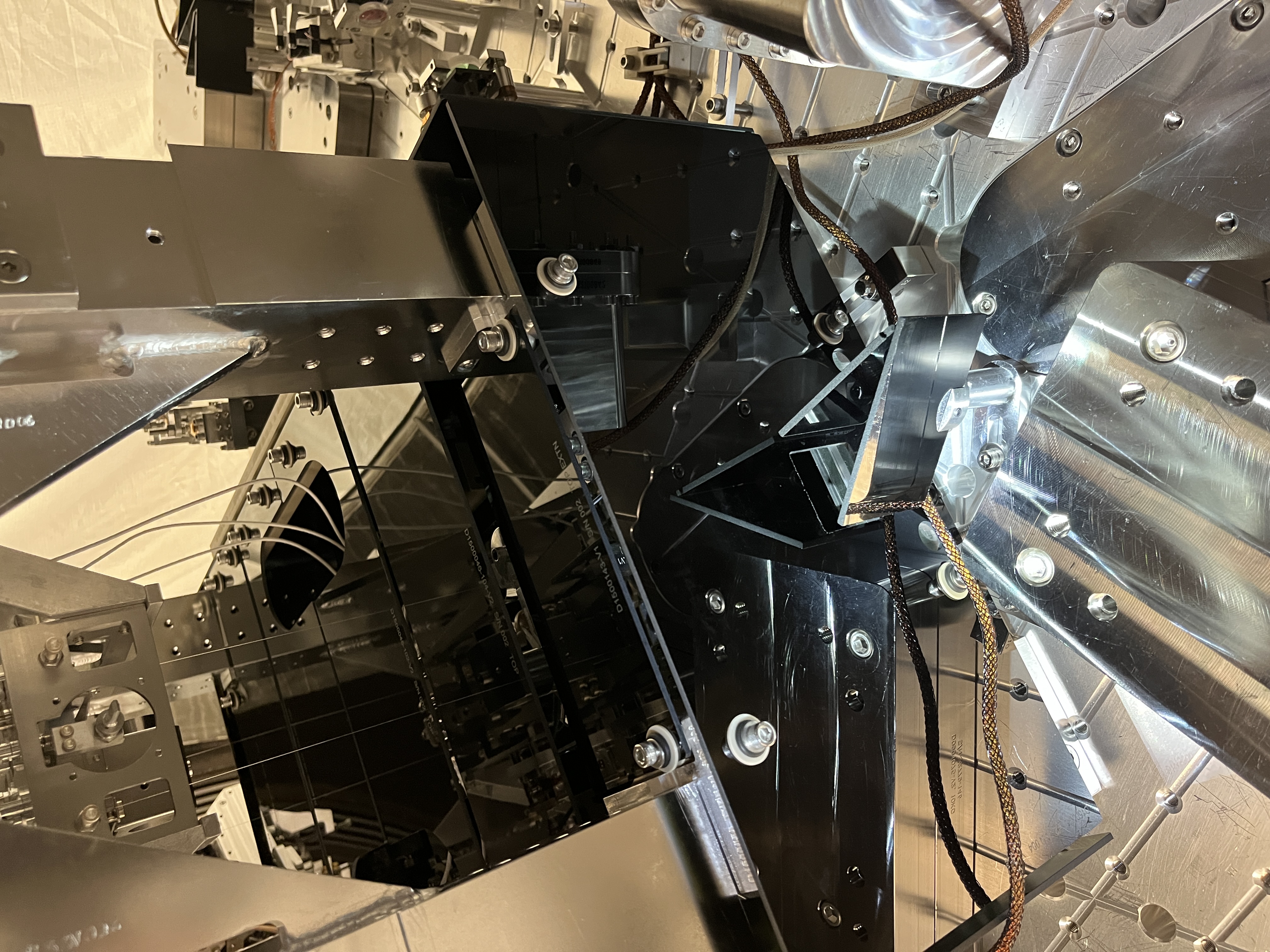
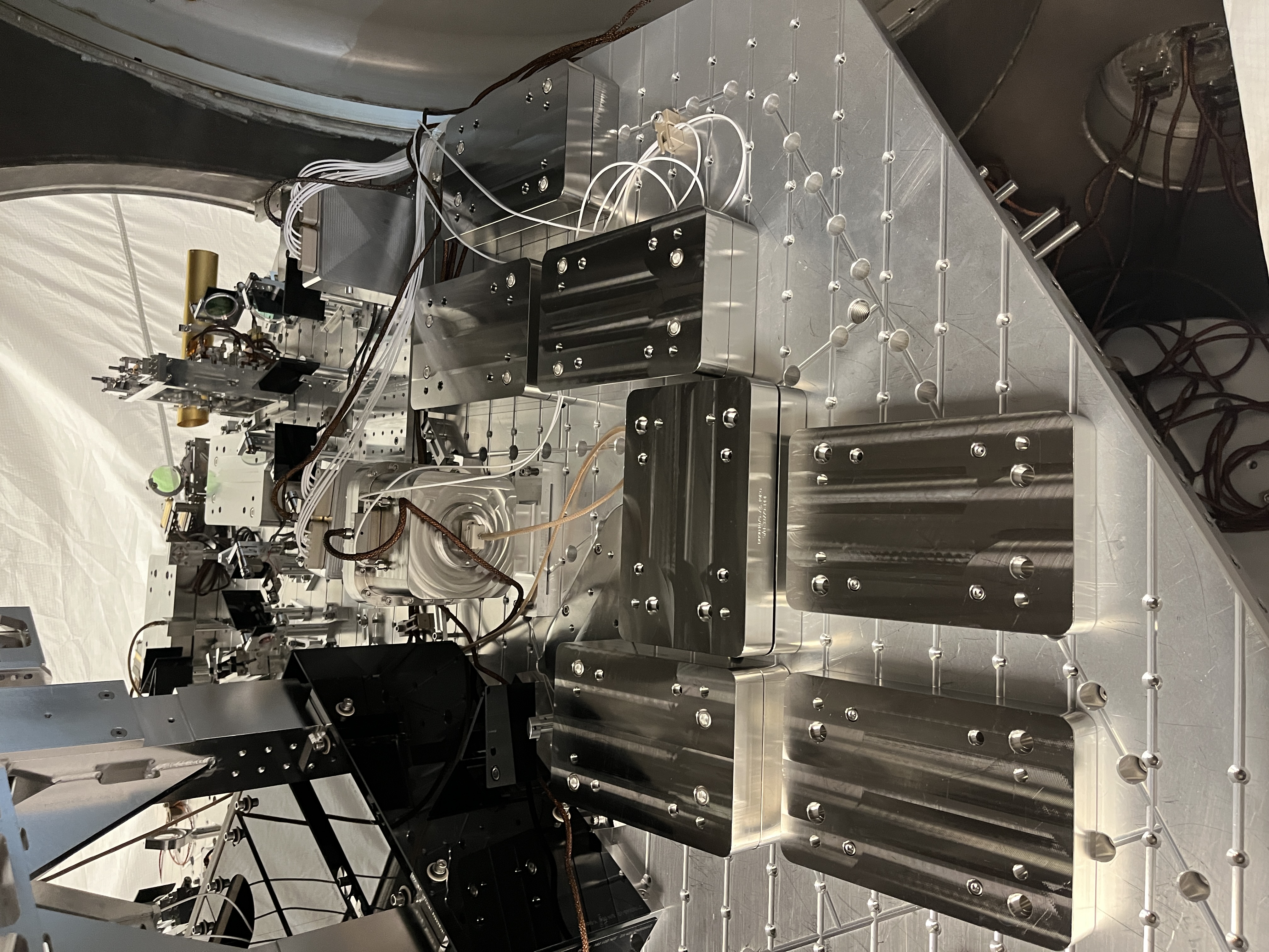
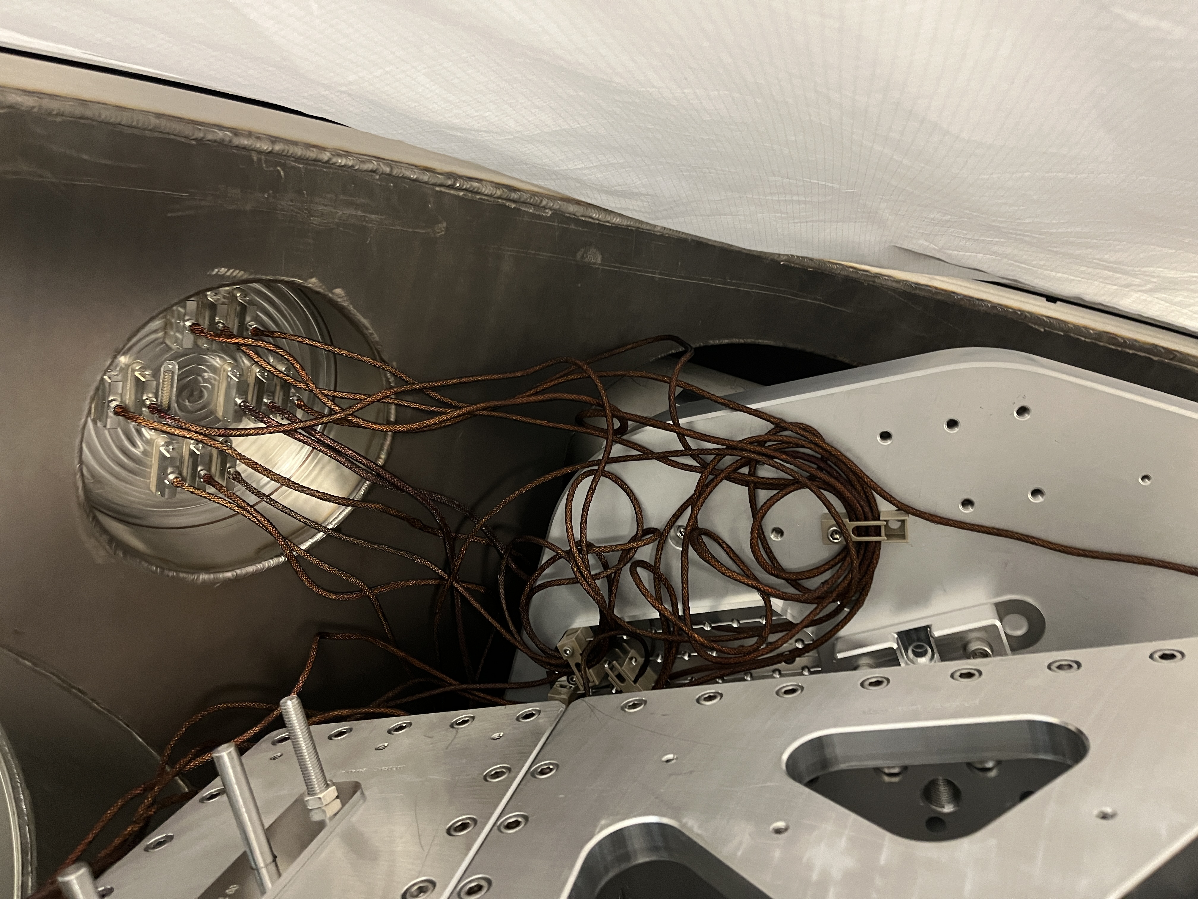
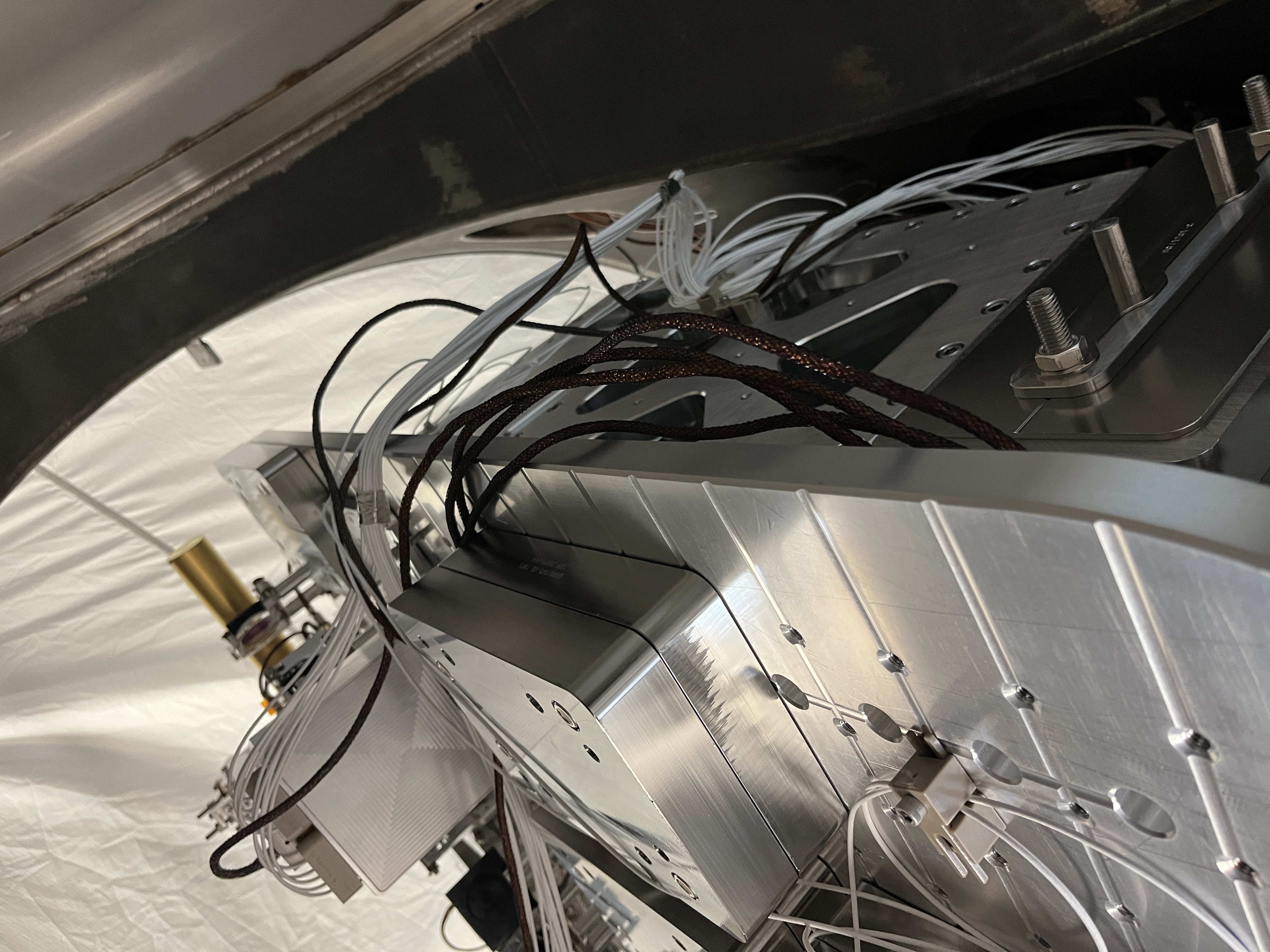
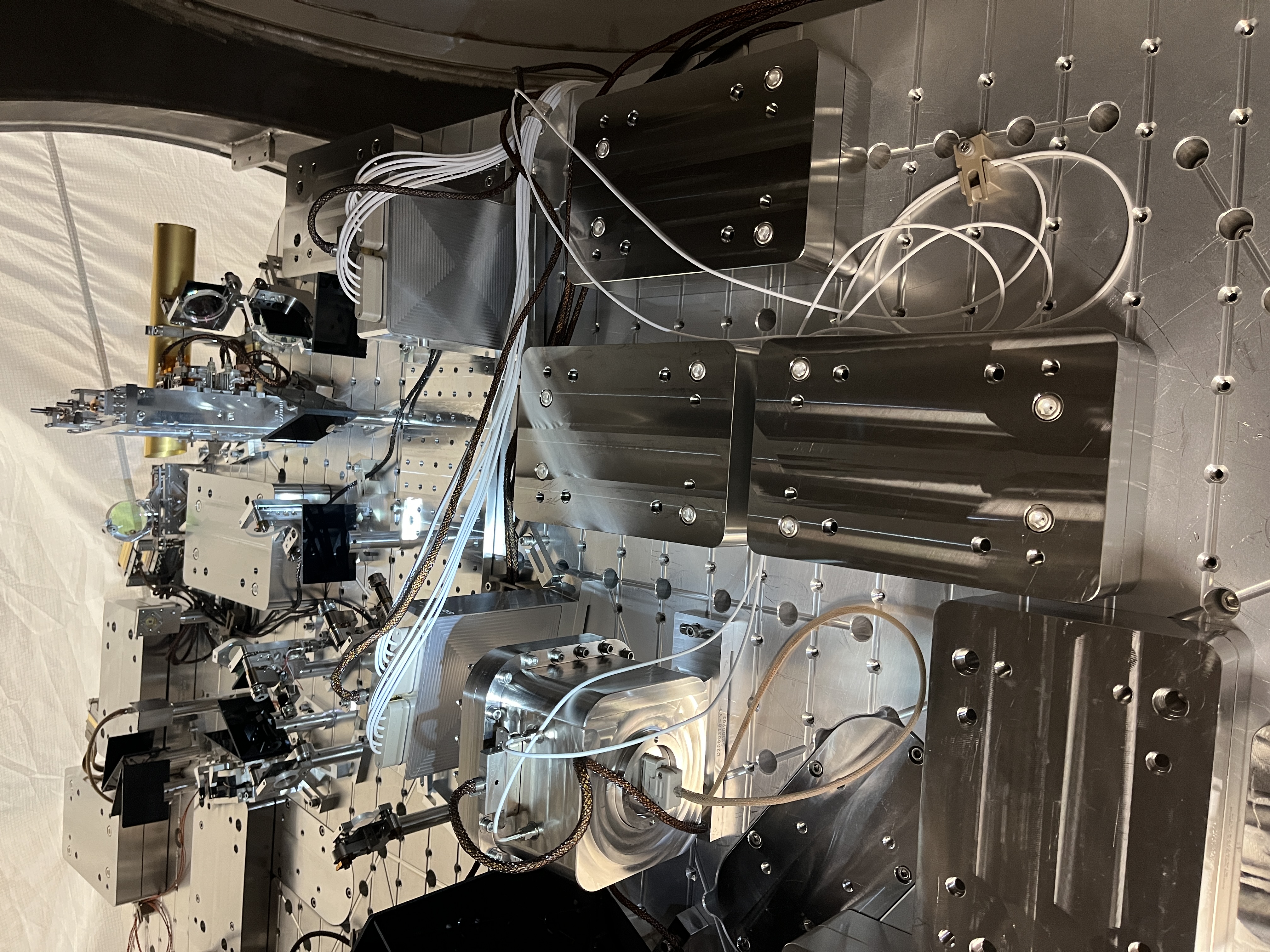

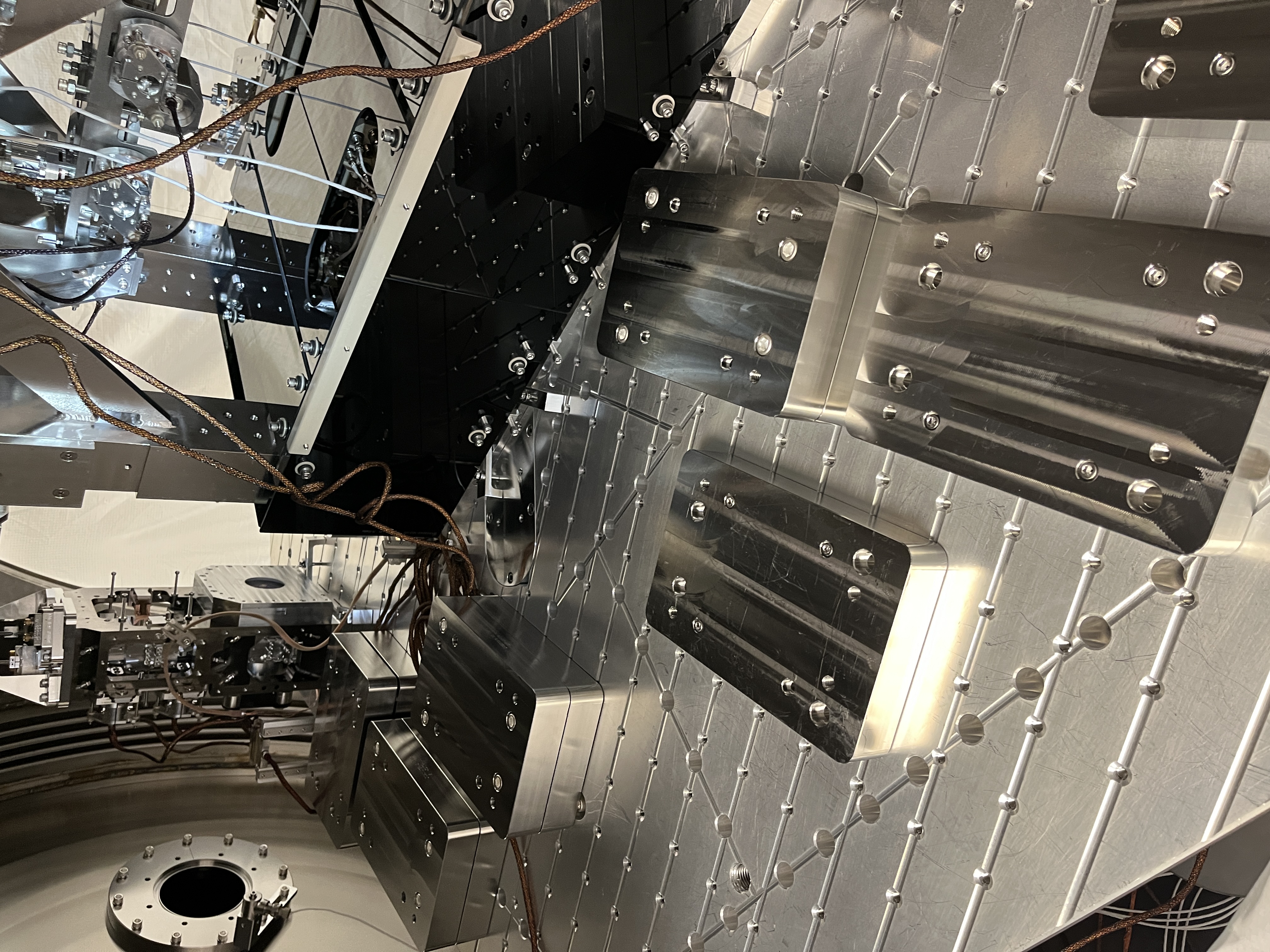
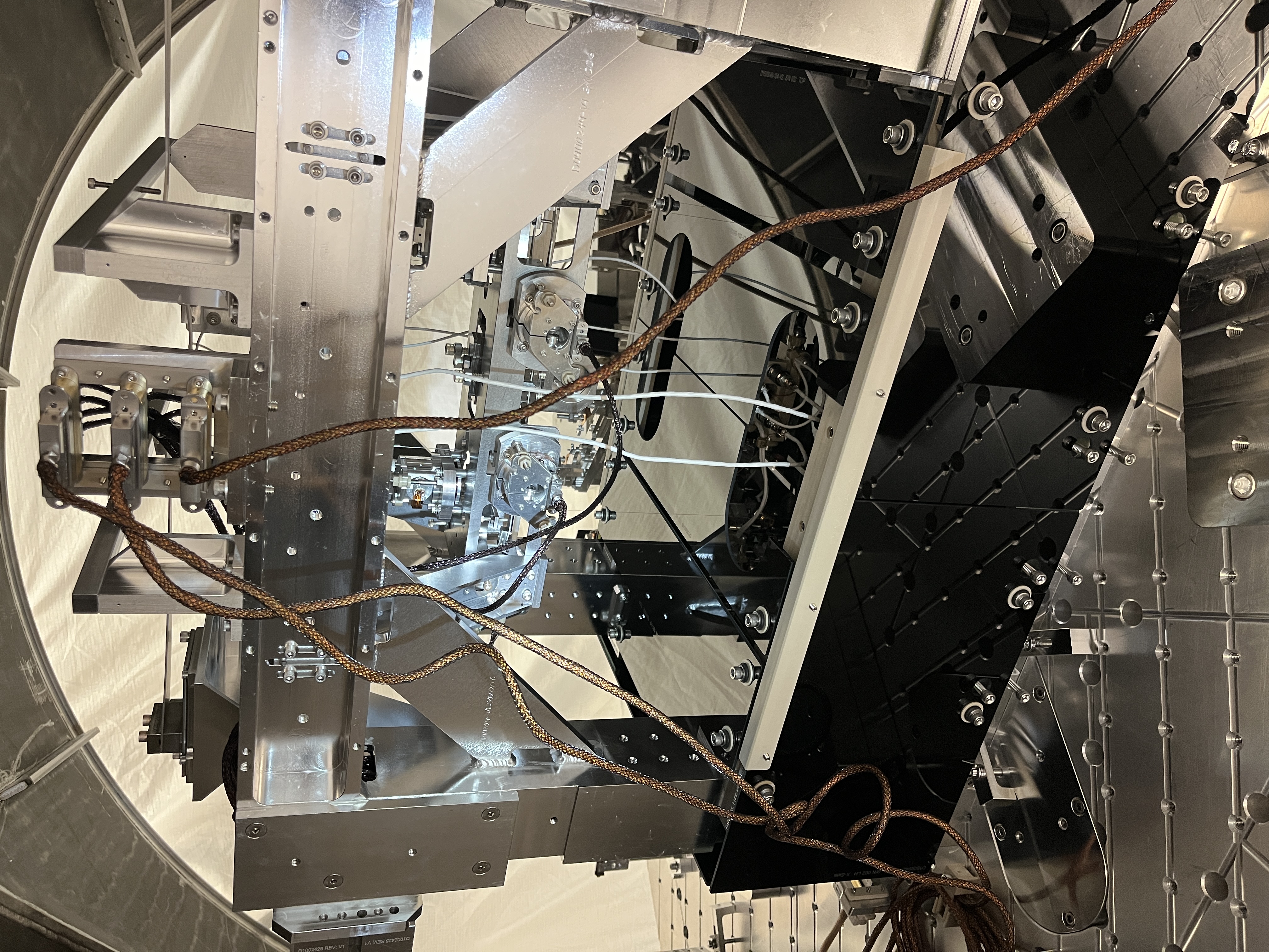
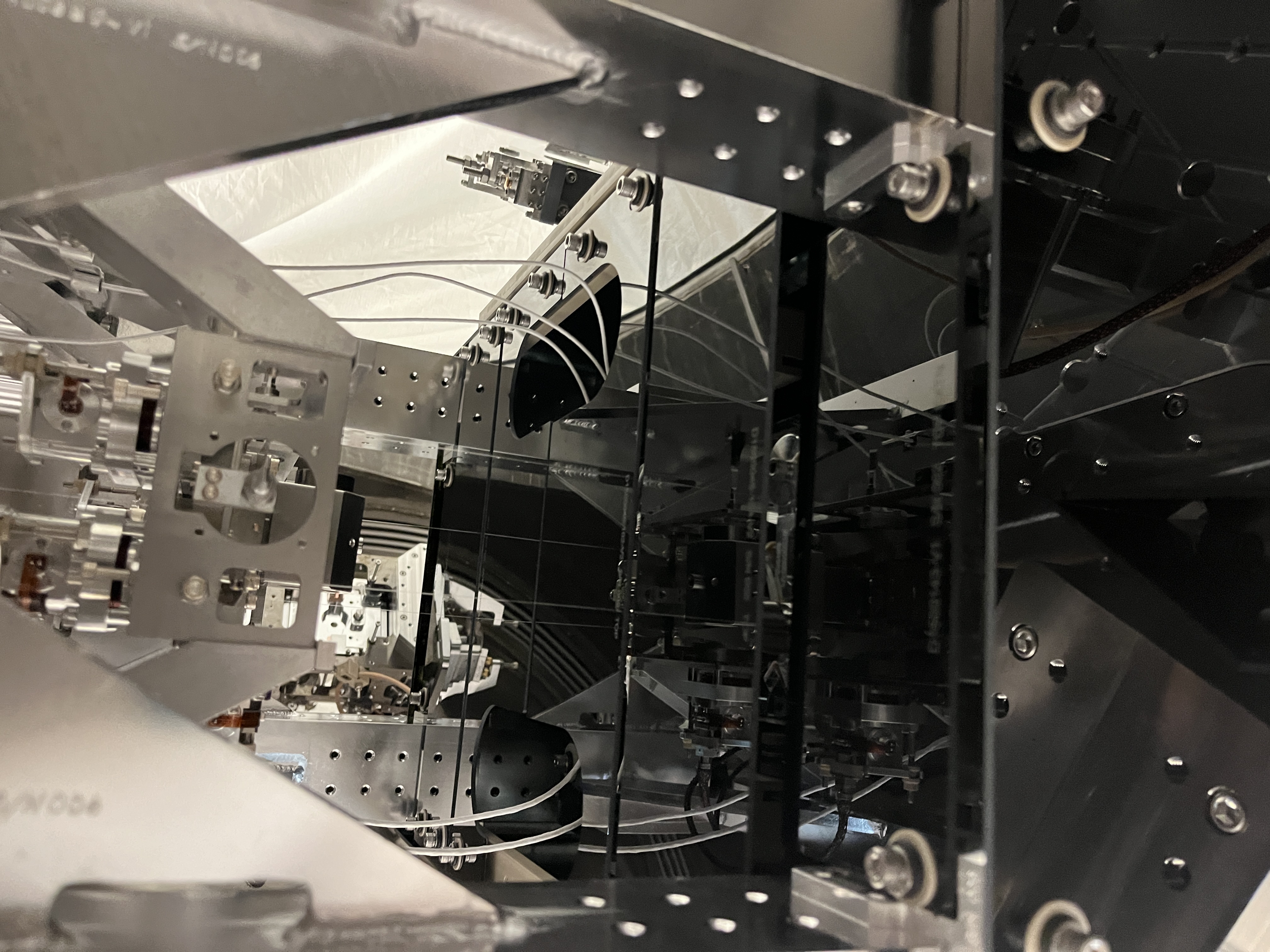
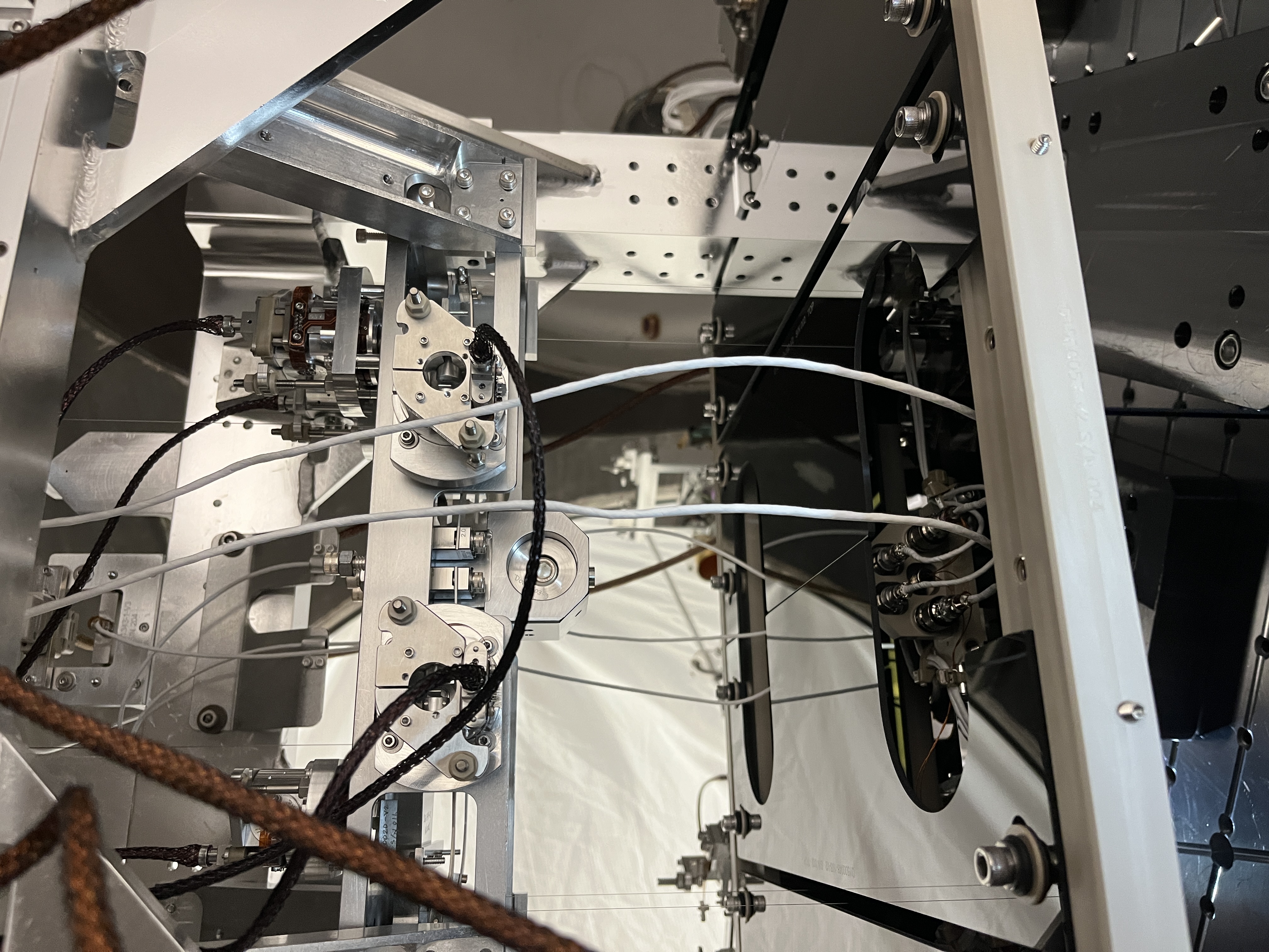
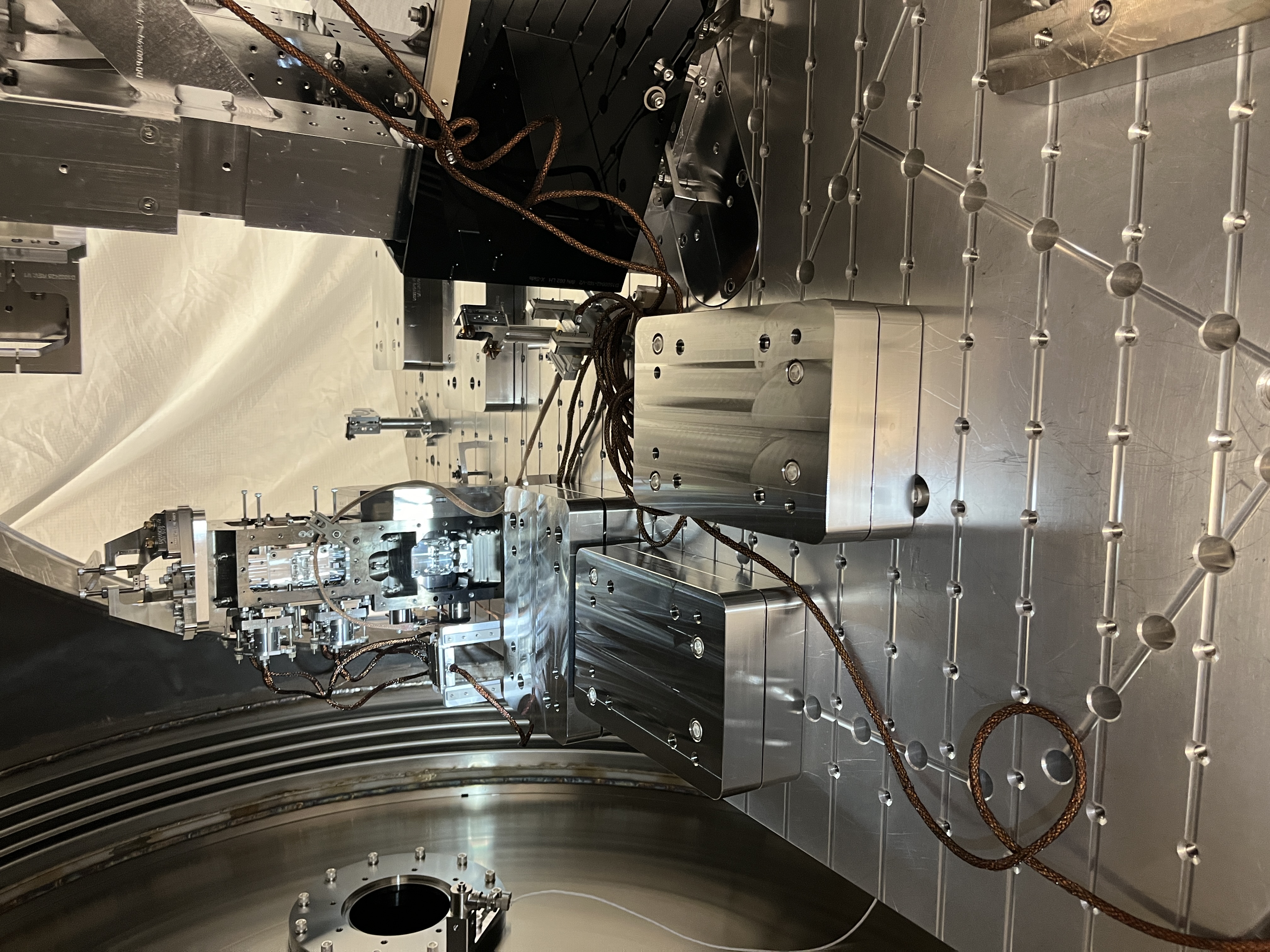
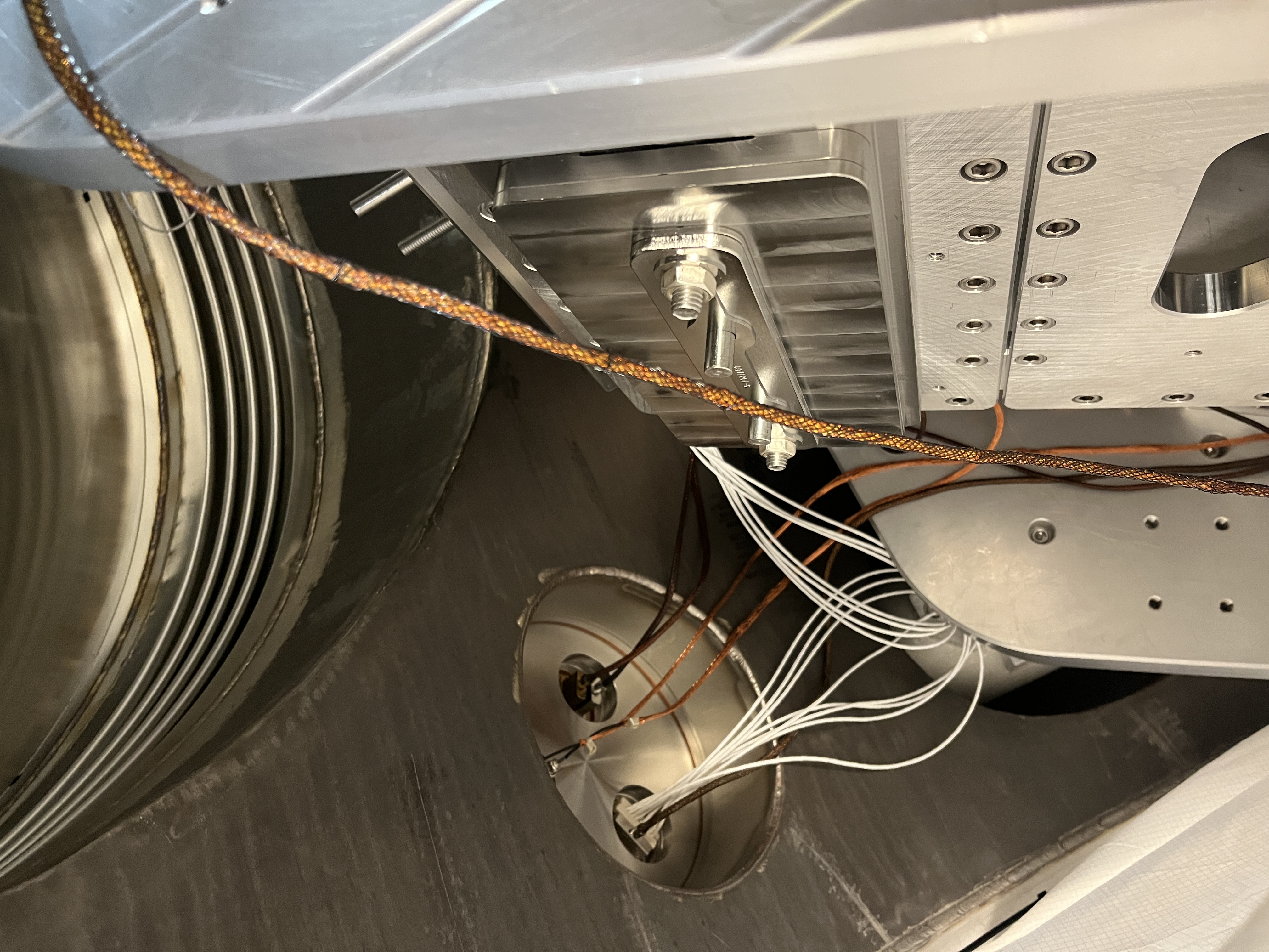
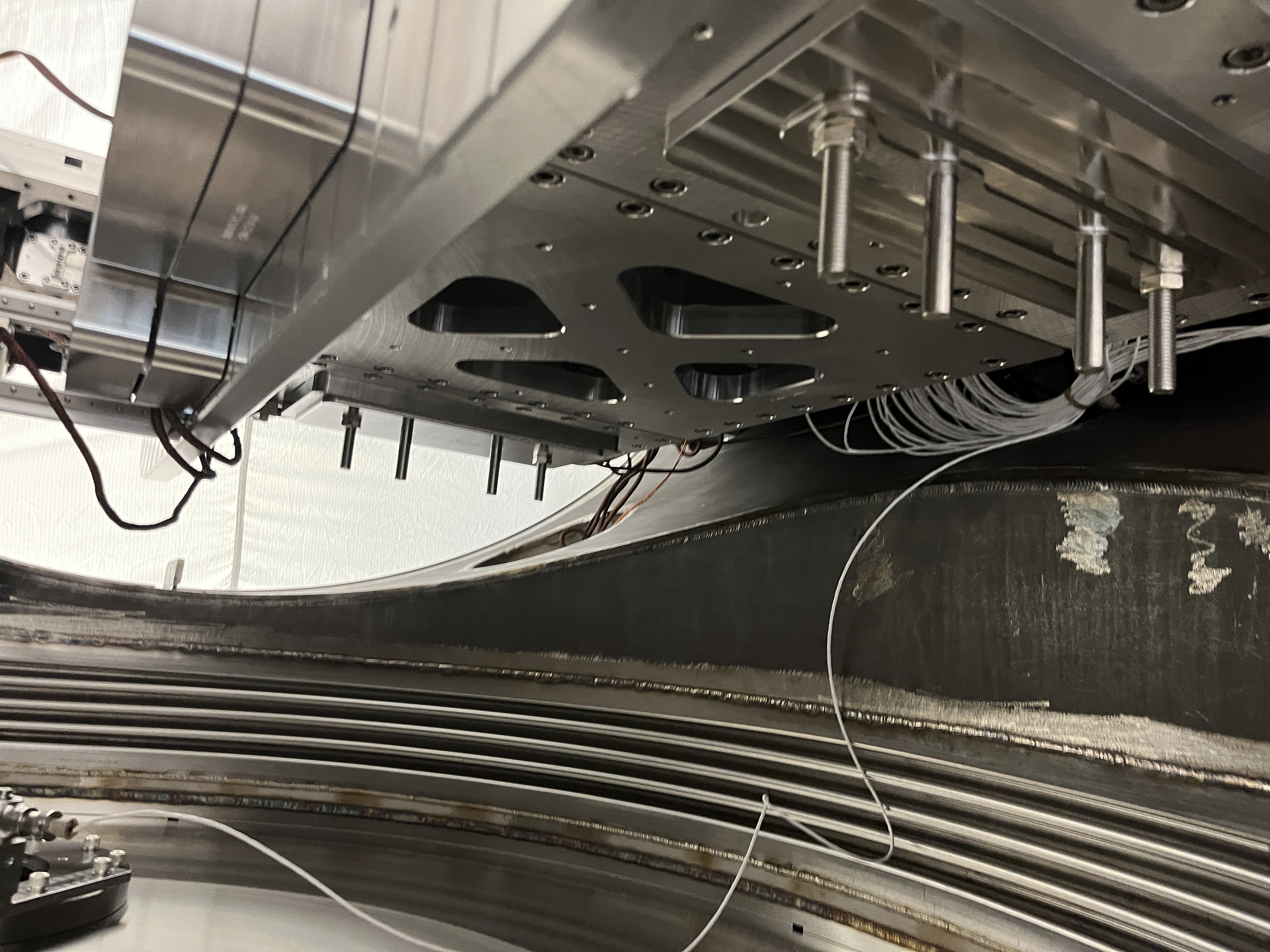
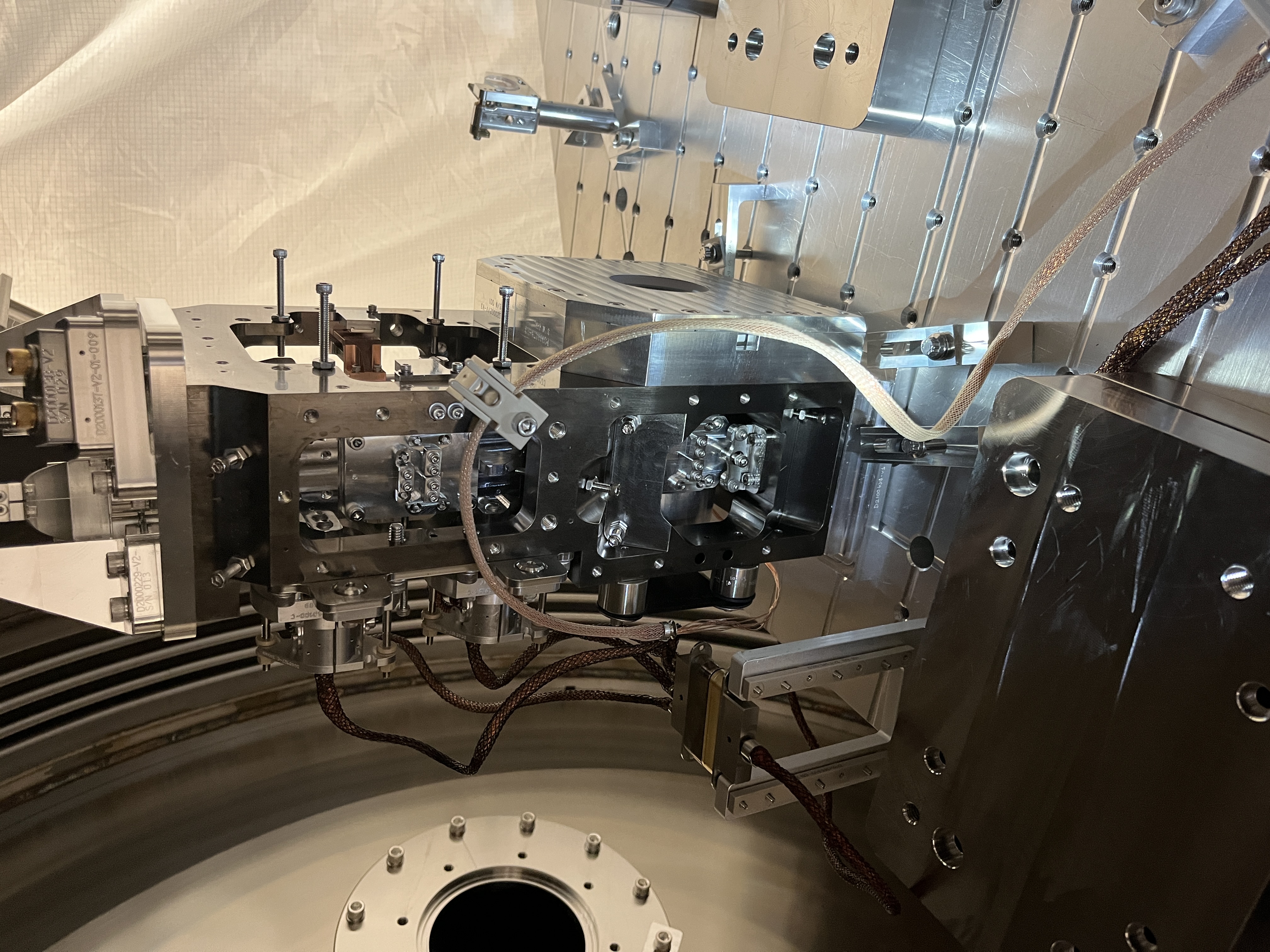
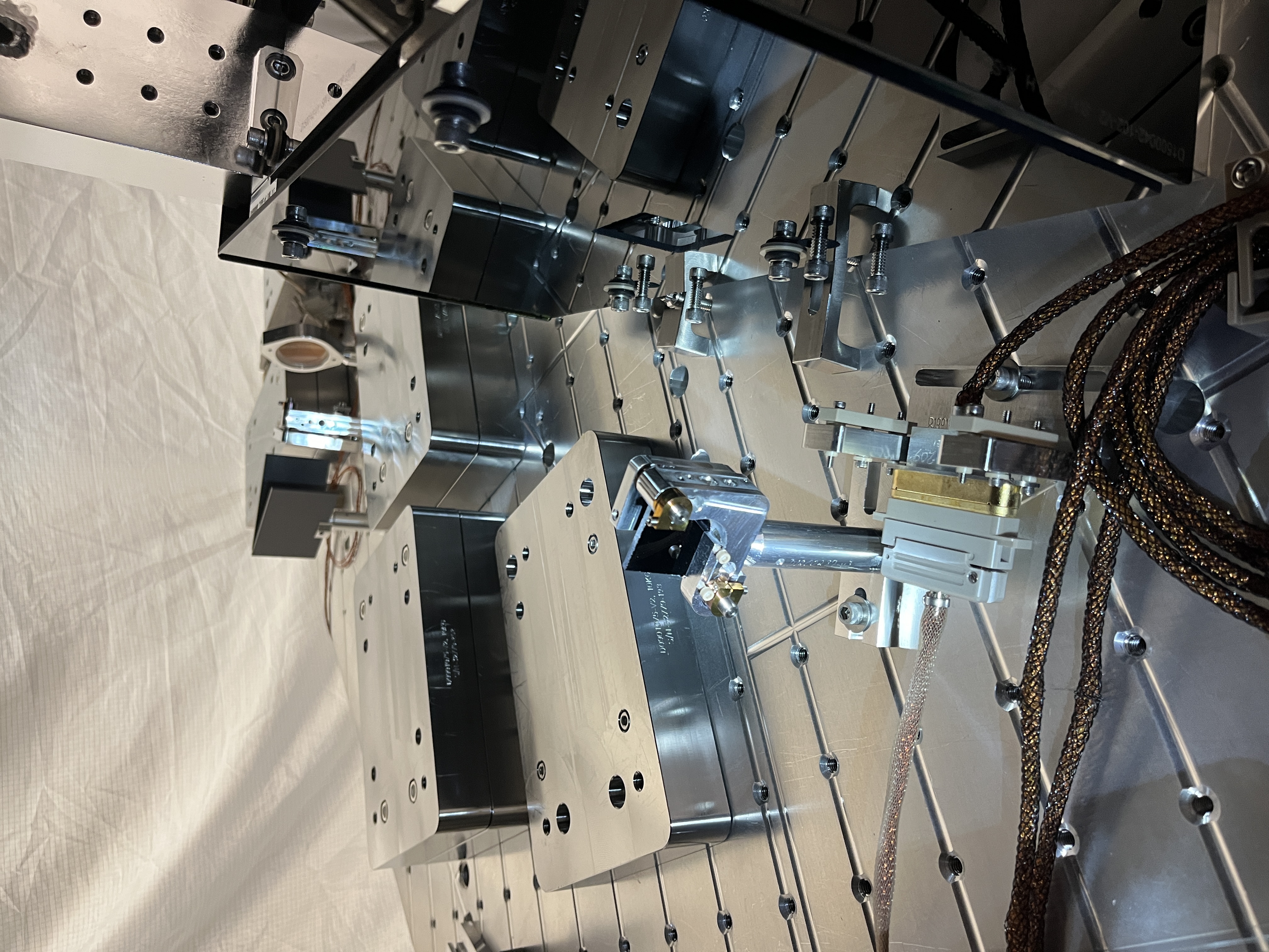
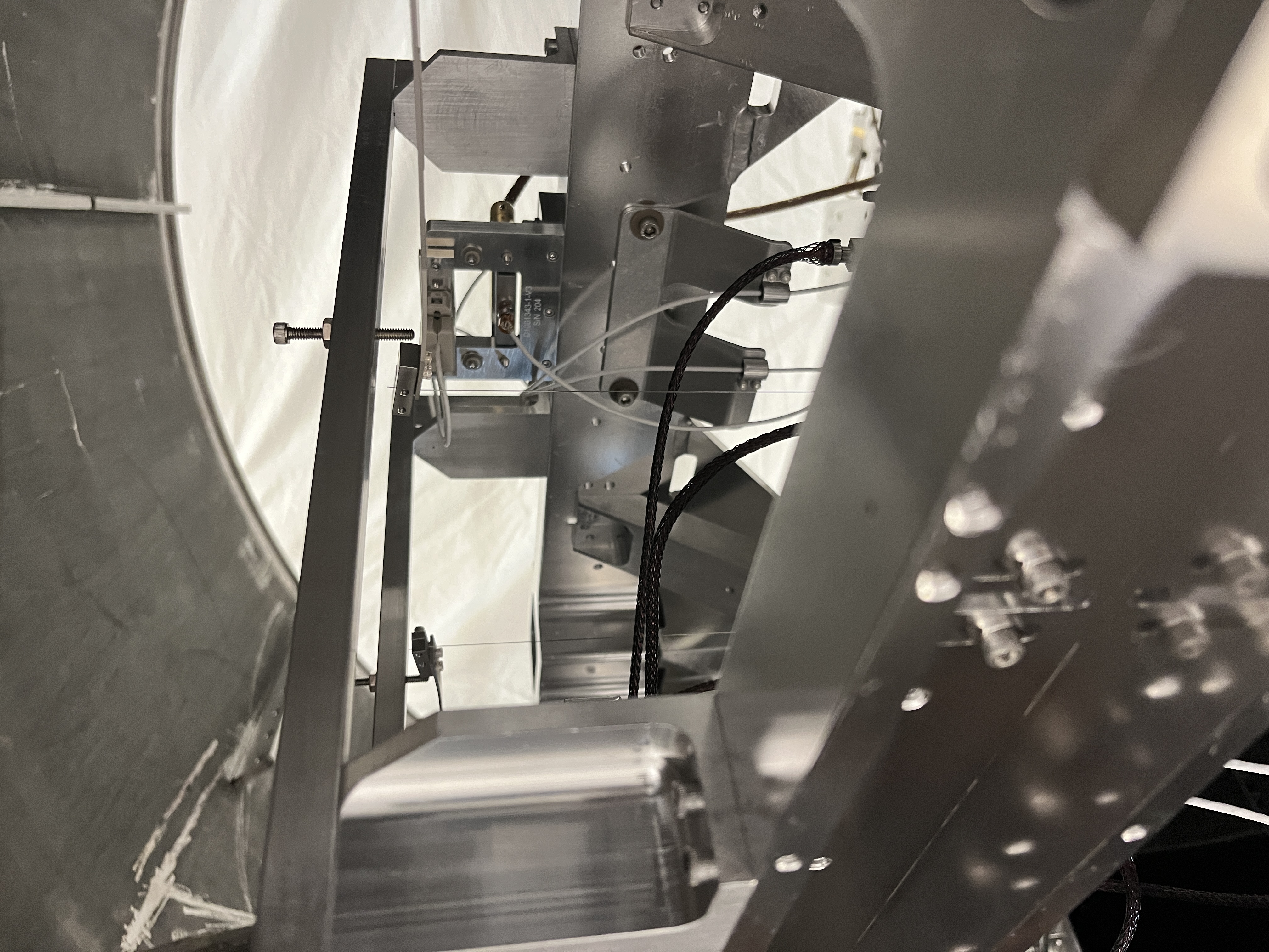
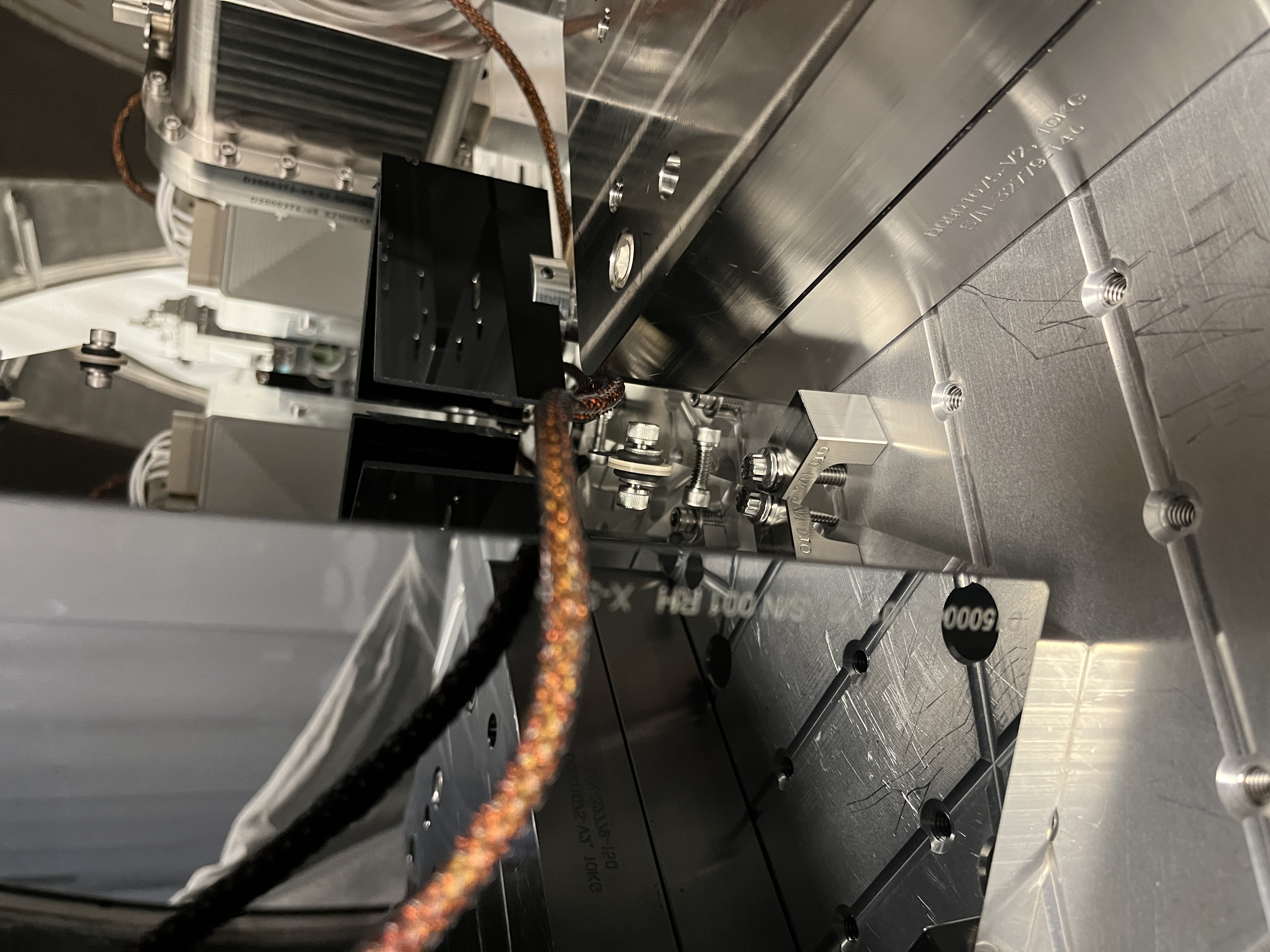
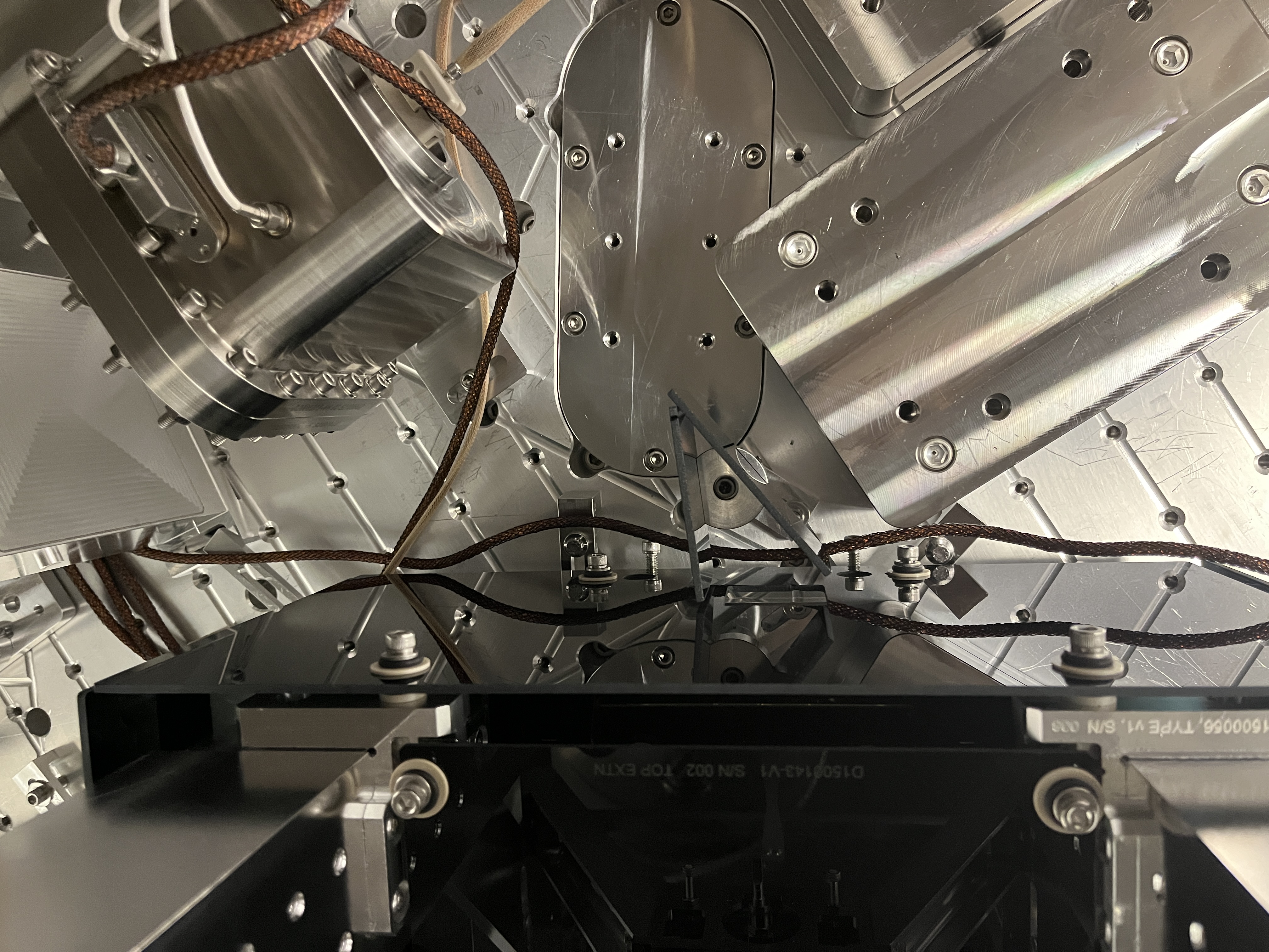
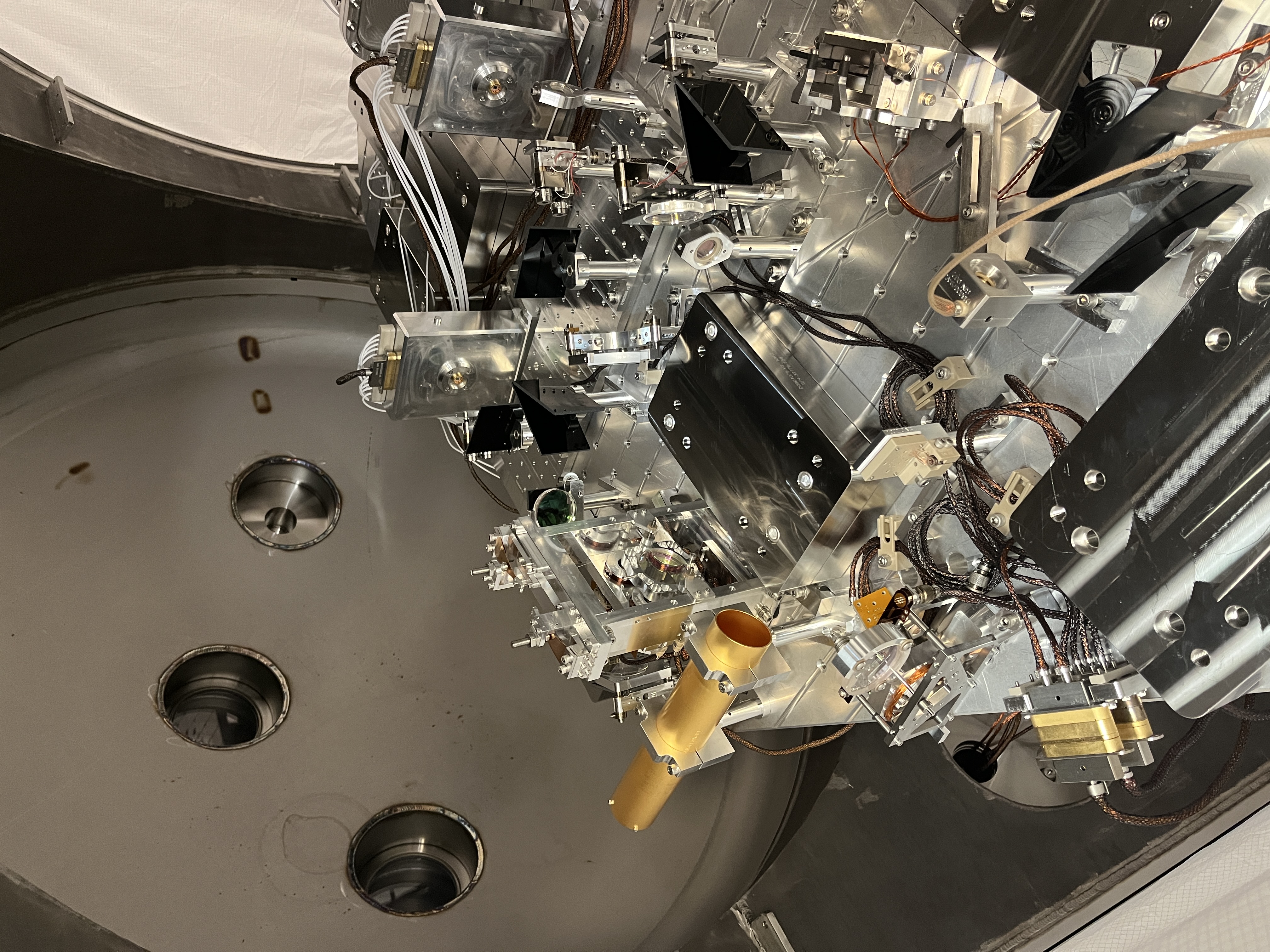
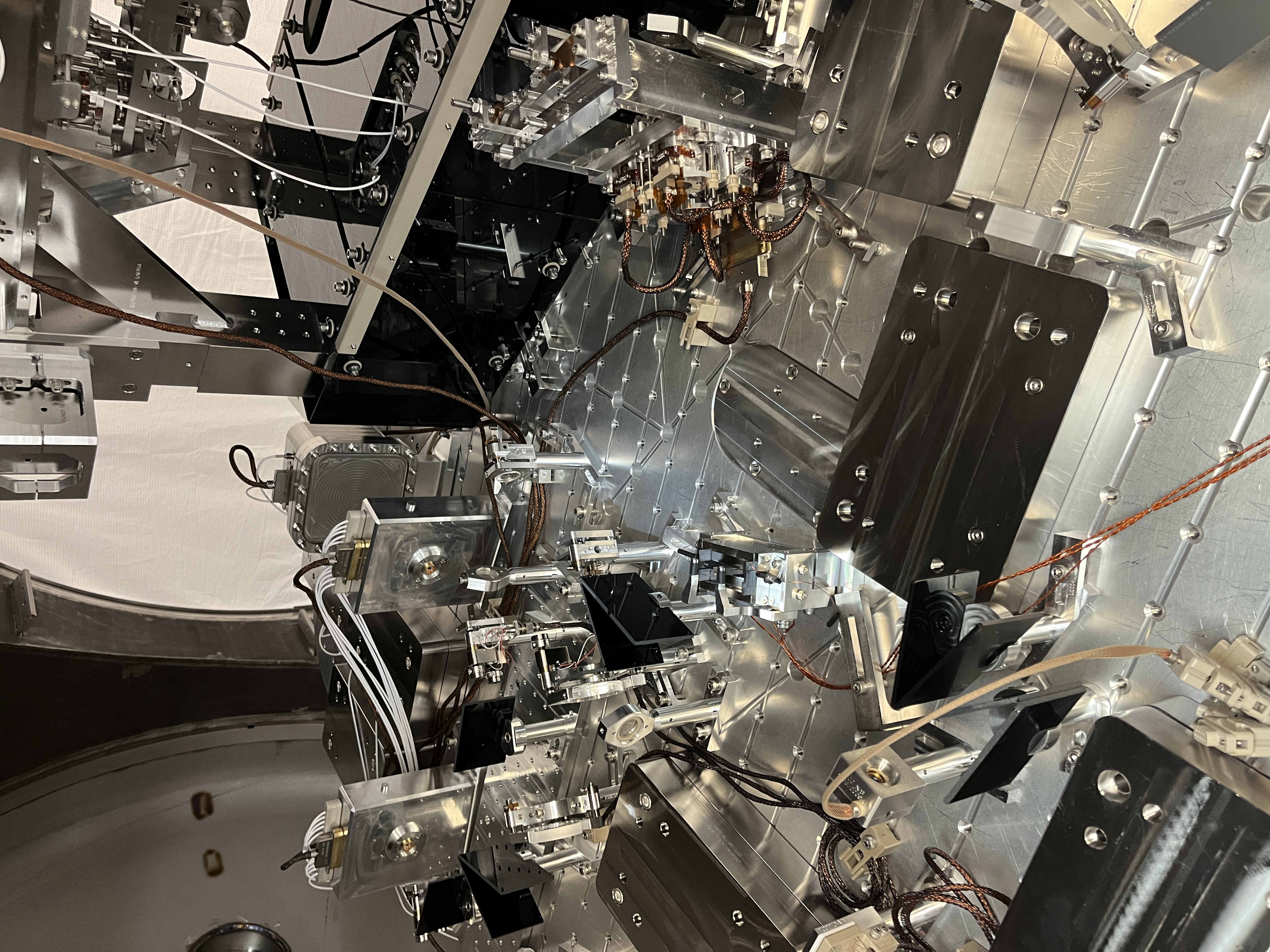
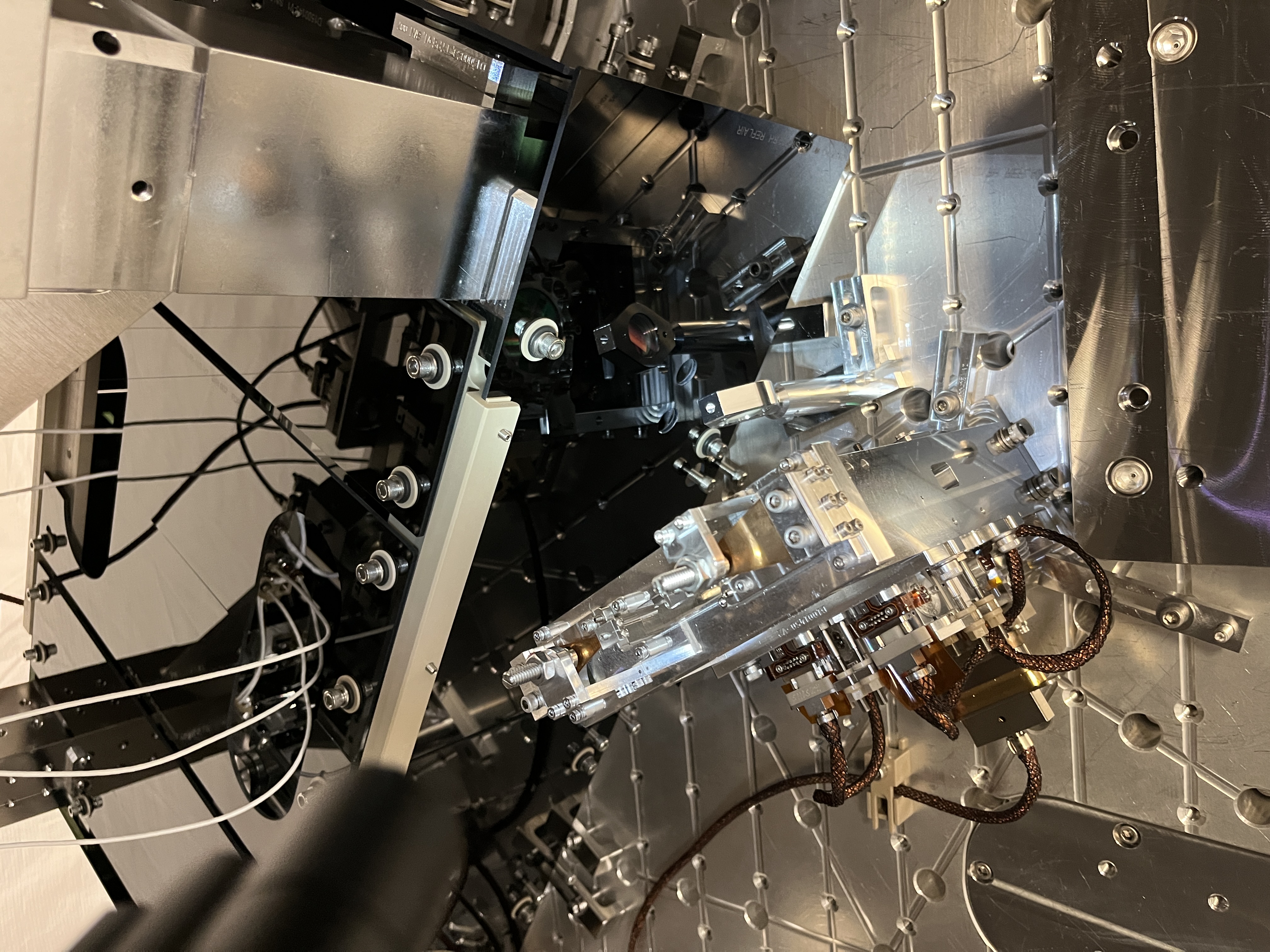

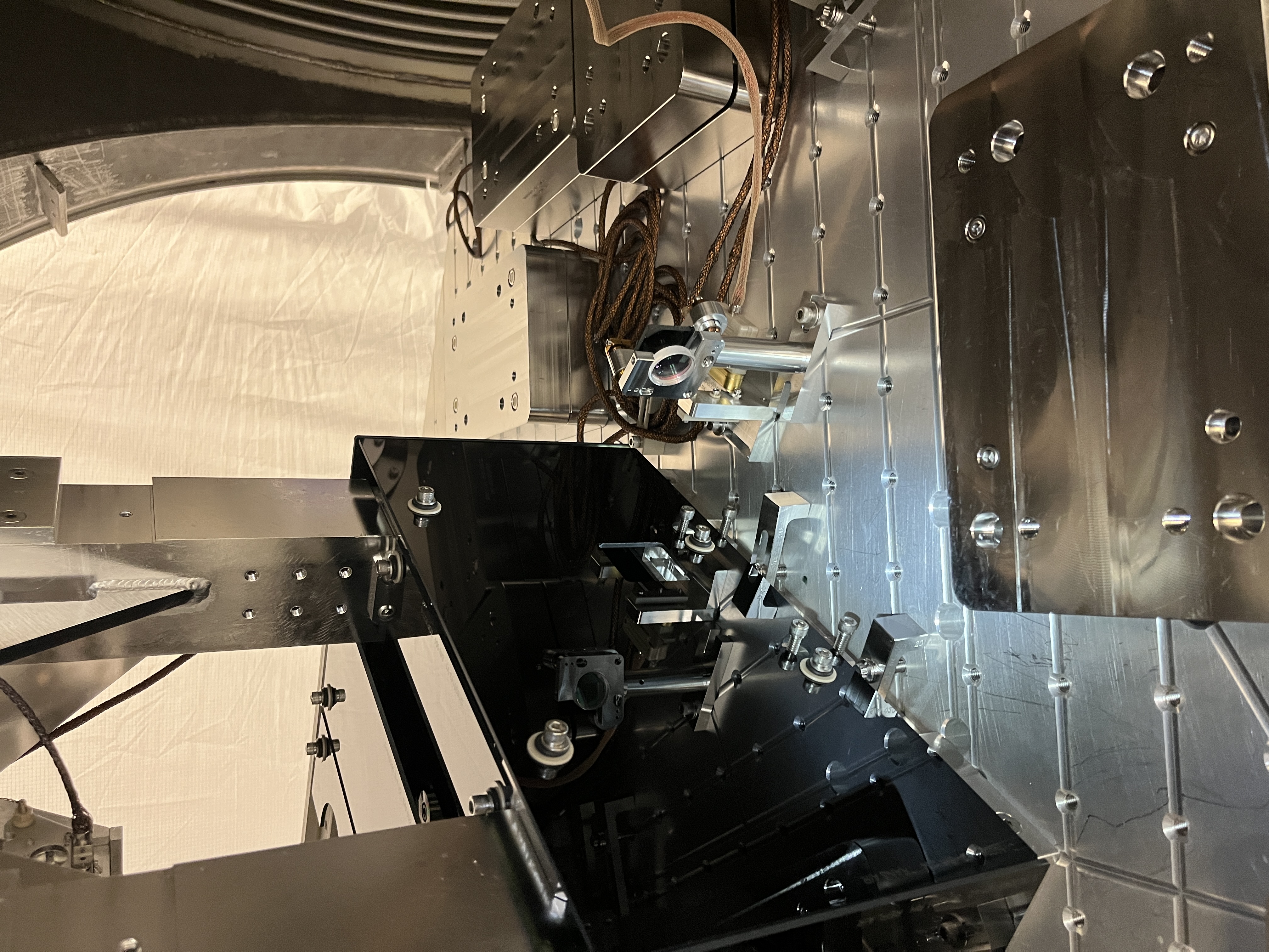
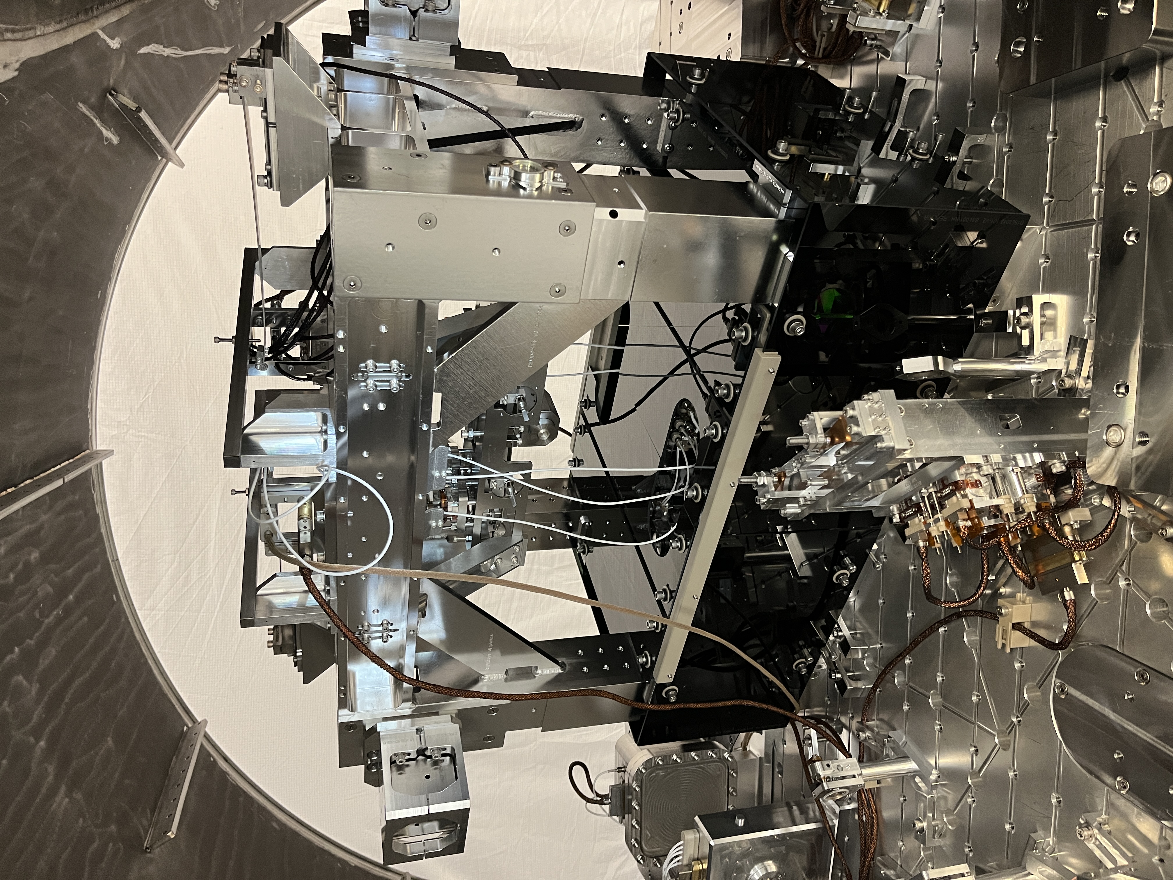
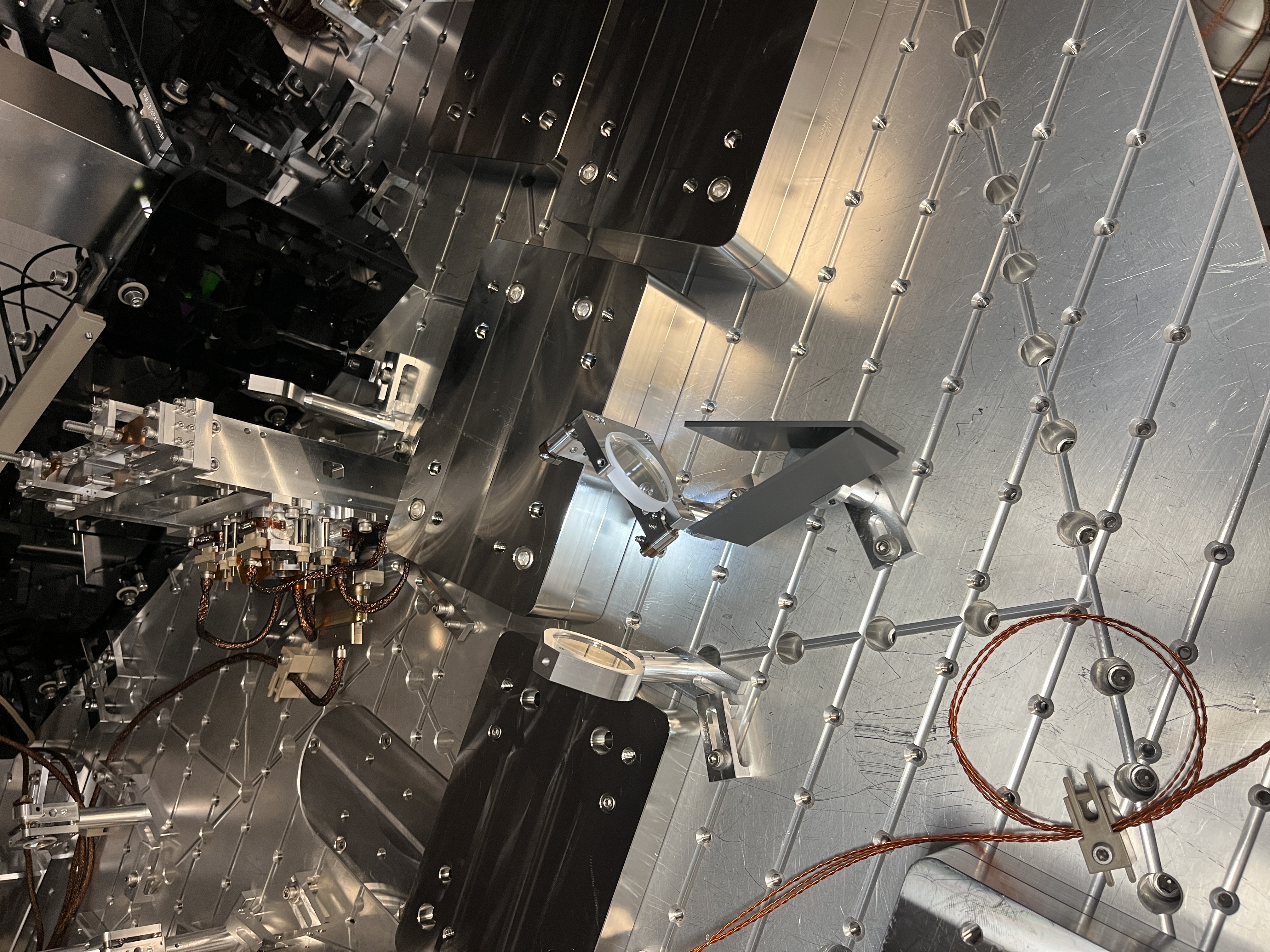
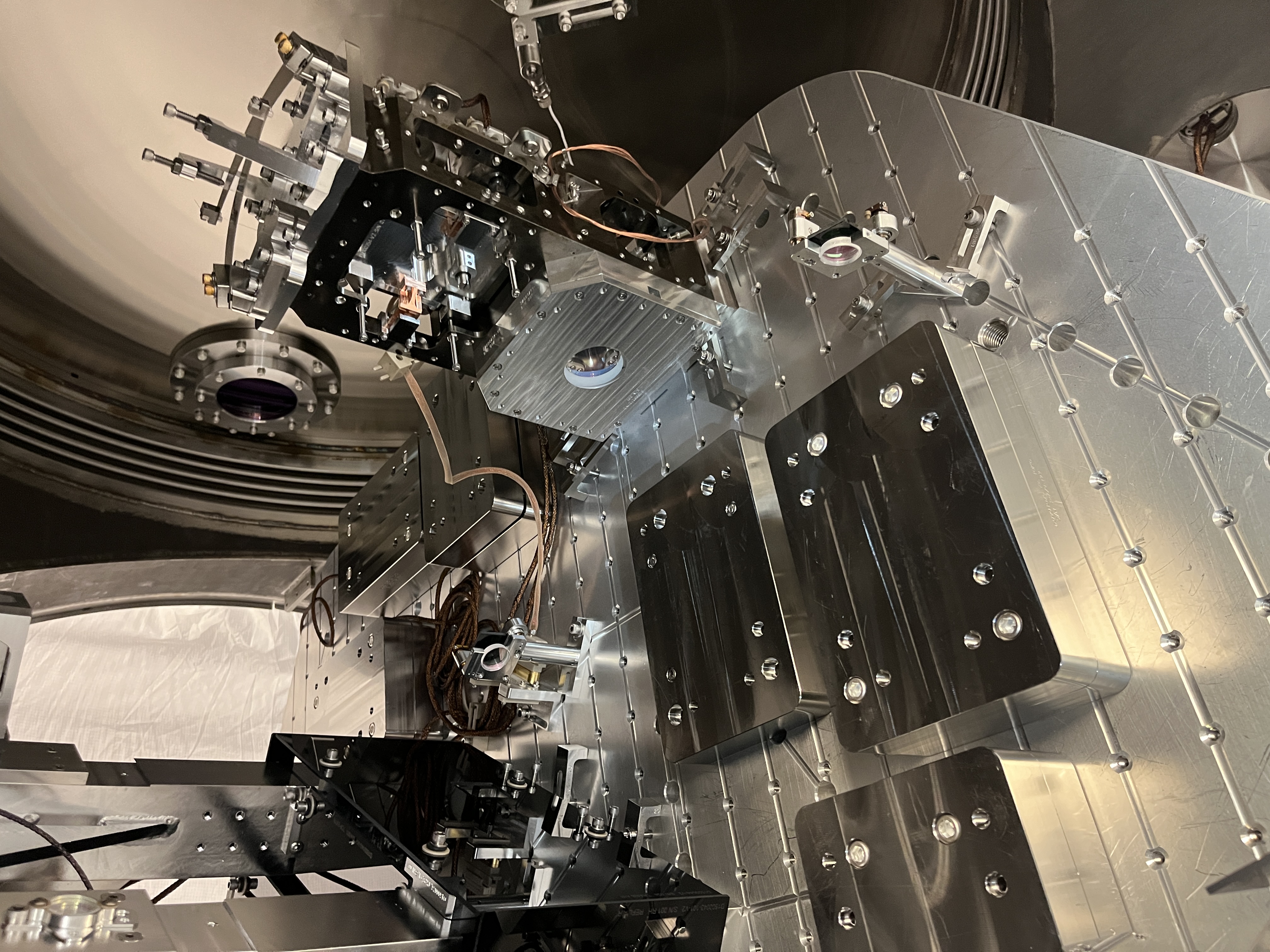
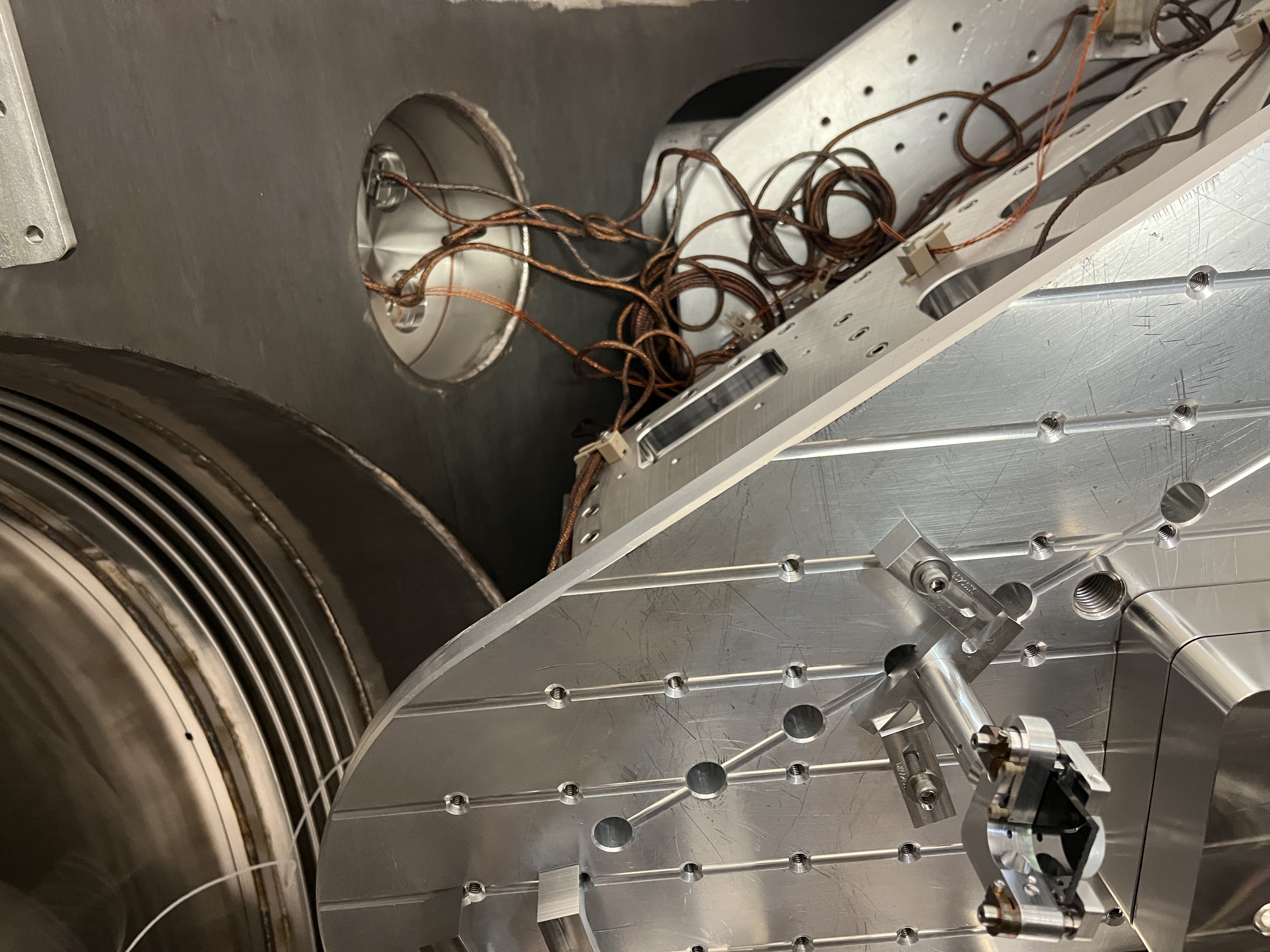
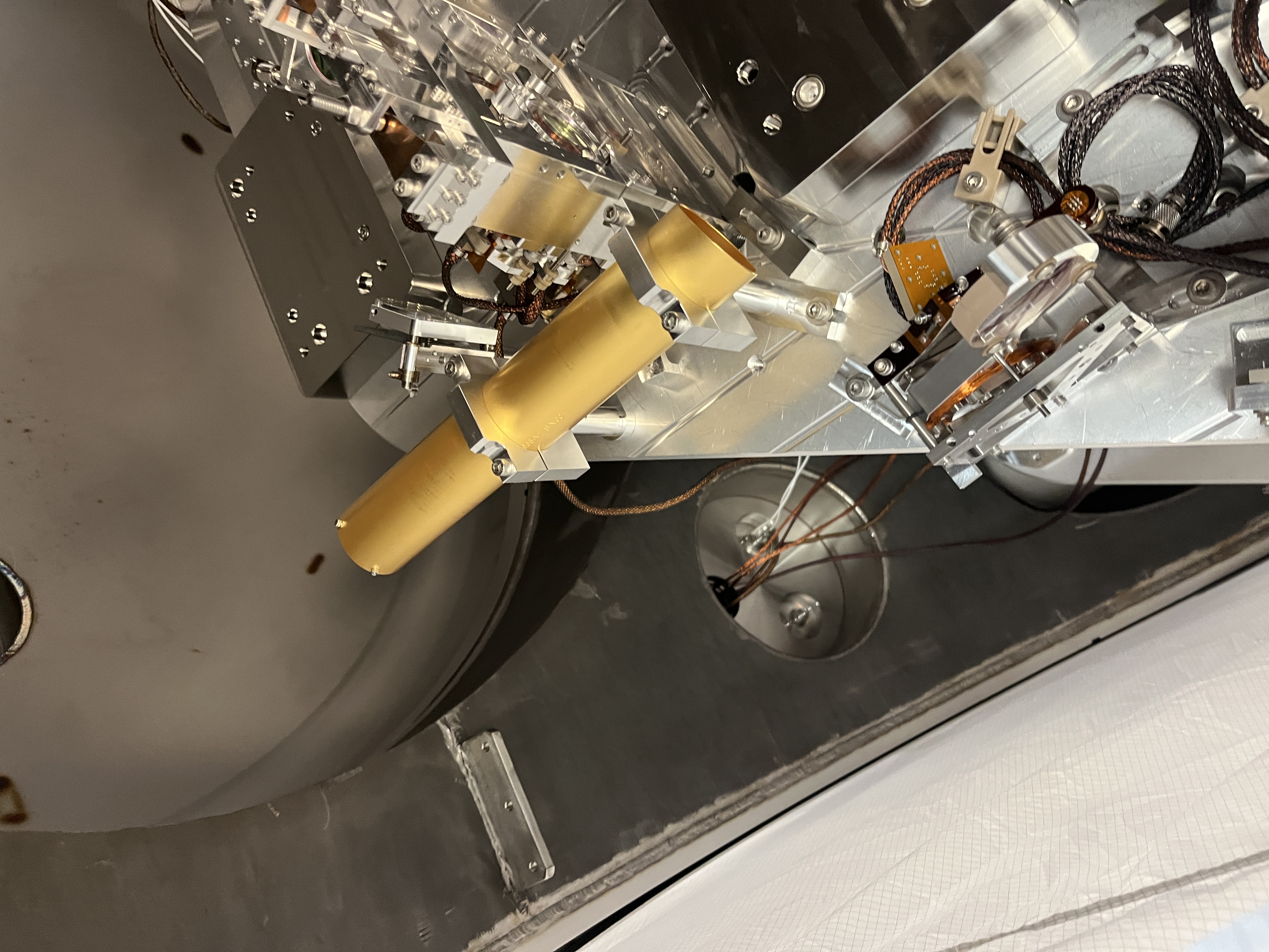
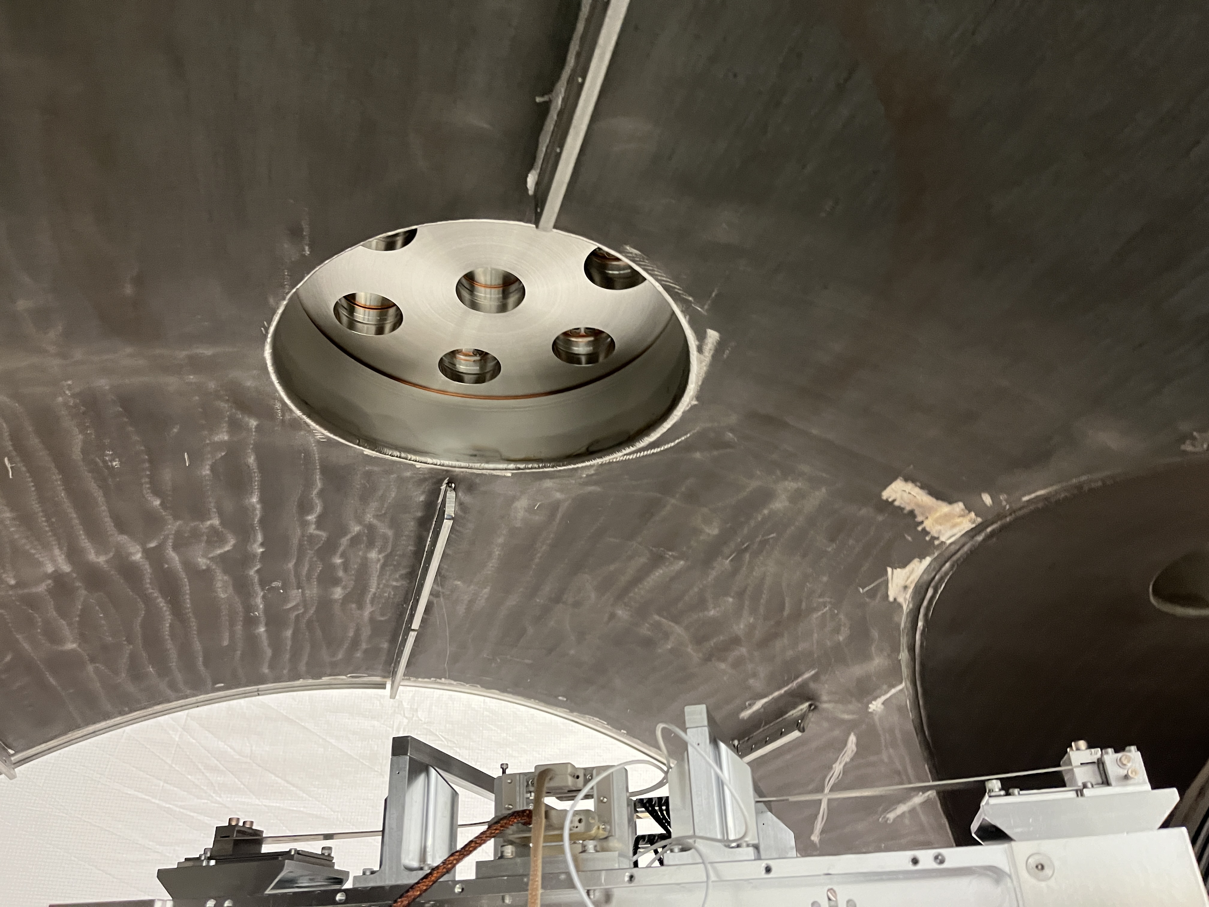
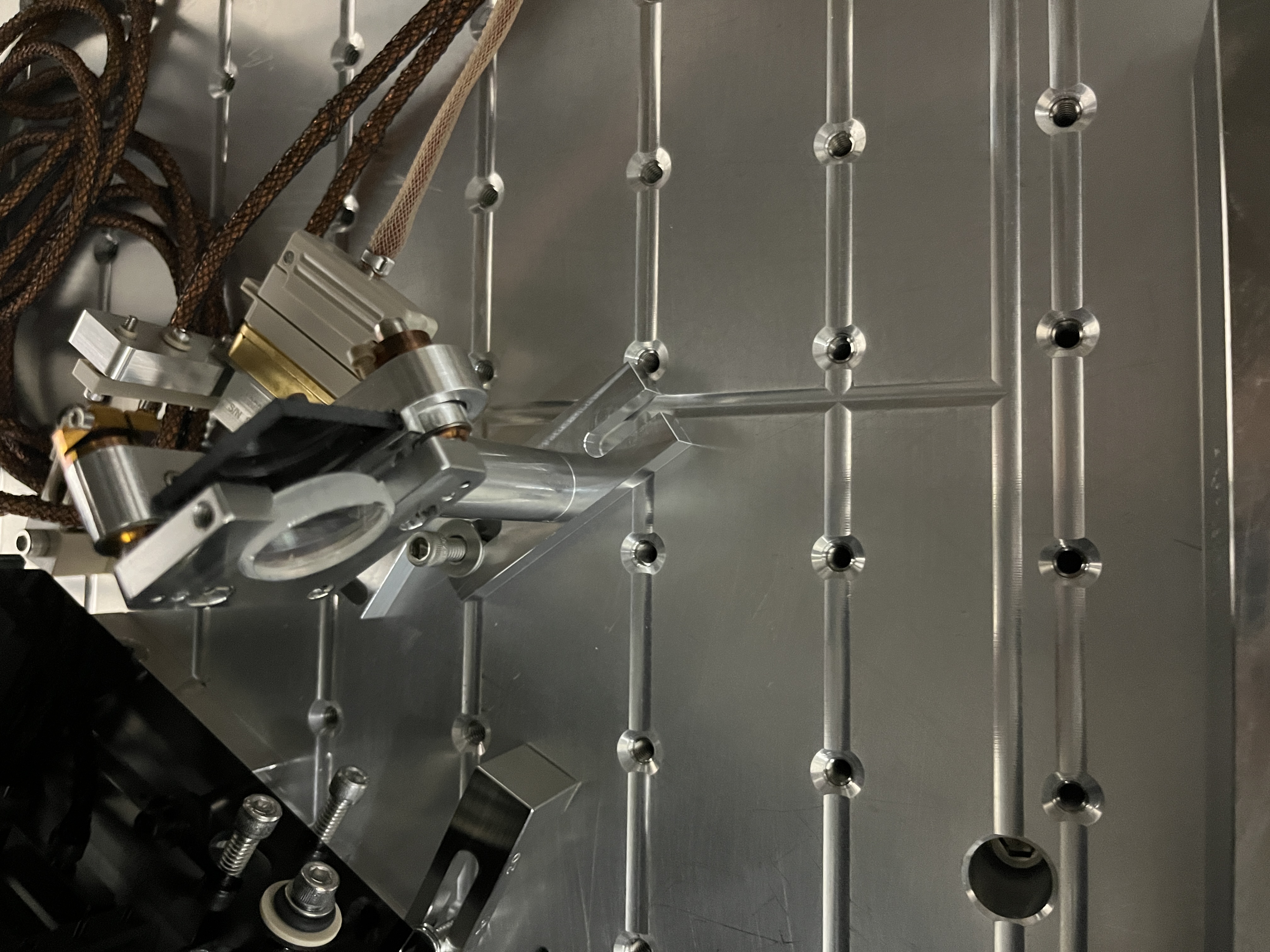
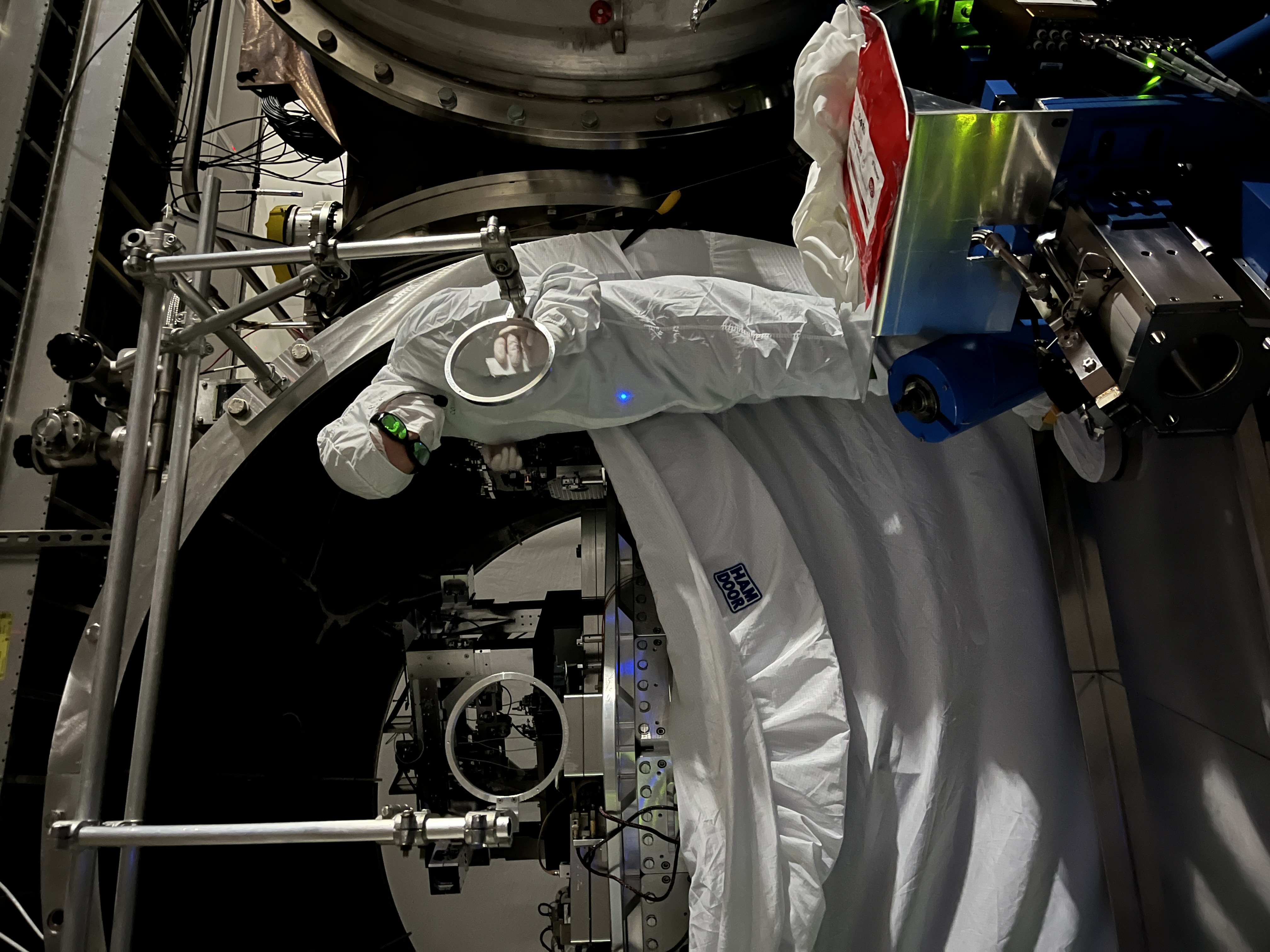
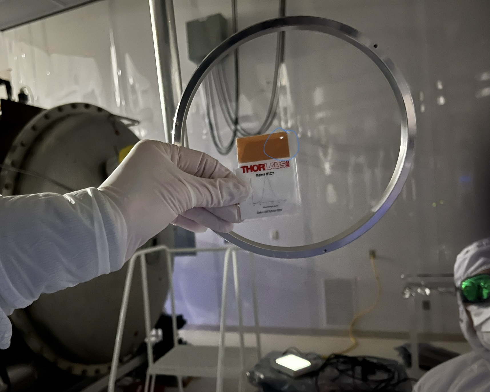
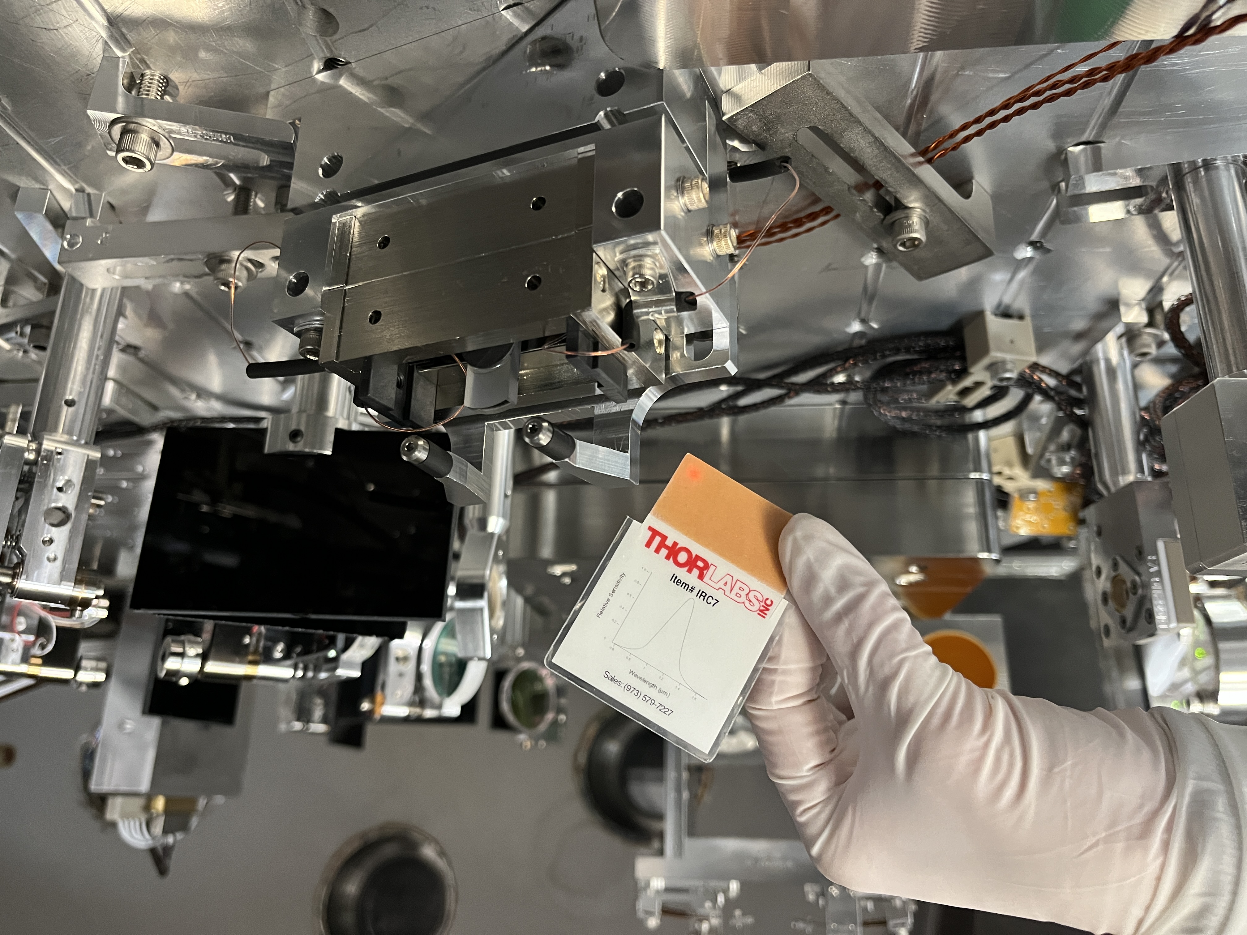
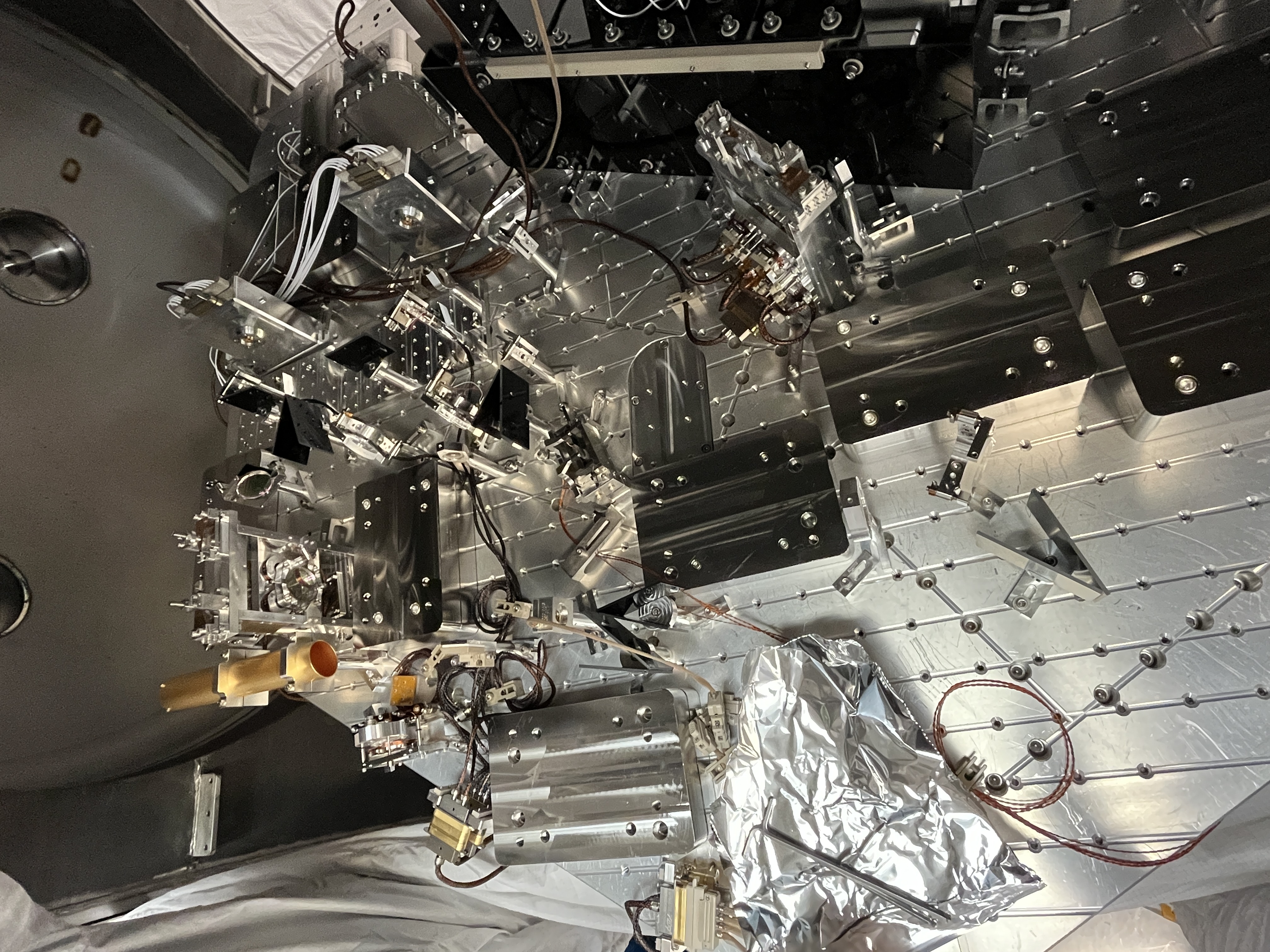
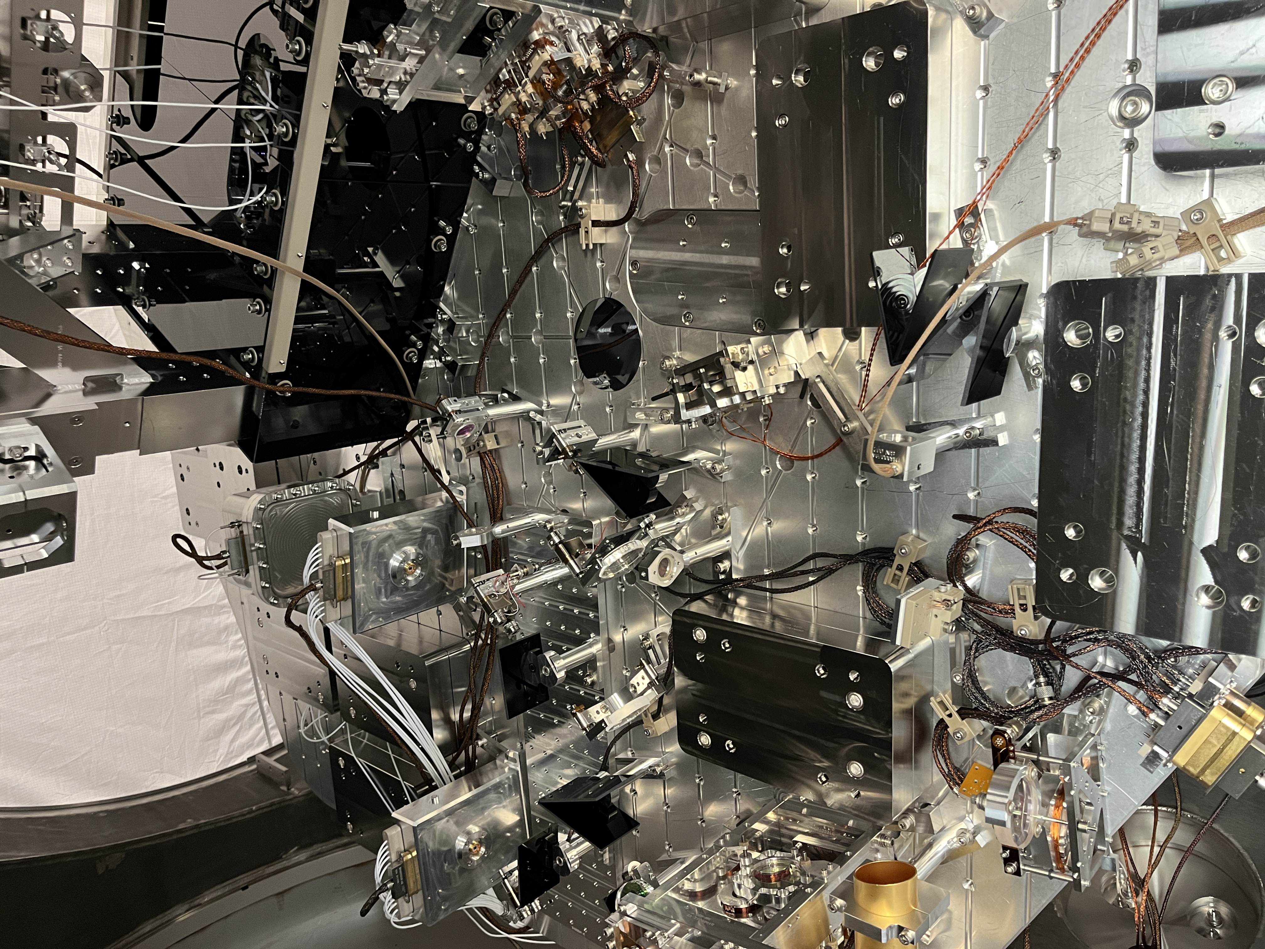
Tagging EPO for HAM6/OMC photos