eric.otterman@LIGO.ORG - posted 11:03, Wednesday 21 January 2026 (88832)
FCES air handler
The pre-filters were replaced in the FCES air handler.
The pre-filters were replaced in the FCES air handler.
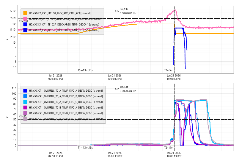
Wed Jan 21 10:08:13 2026 INFO: Fill completed in 8min 10secs
Closes FAMIS#39334, last checked 88680
The elevated sensors listed are just from HAM1 and HAM7, which is expected
All chambers are looking normal relative to the current state that they are in (locked, vented, etc)
TITLE: 01/21 Day Shift: 1530-0030 UTC (0730-1630 PST), all times posted in UTC
STATE of H1: Planned Engineering
OUTGOING OPERATOR: None
CURRENT ENVIRONMENT:
SEI_ENV state: MAINTENANCE
Wind: 5mph Gusts, 3mph 3min avg
Primary useism: 0.01 μm/s
Secondary useism: 0.17 μm/s
QUICK SUMMARY:
Some of the tasks on the board today:
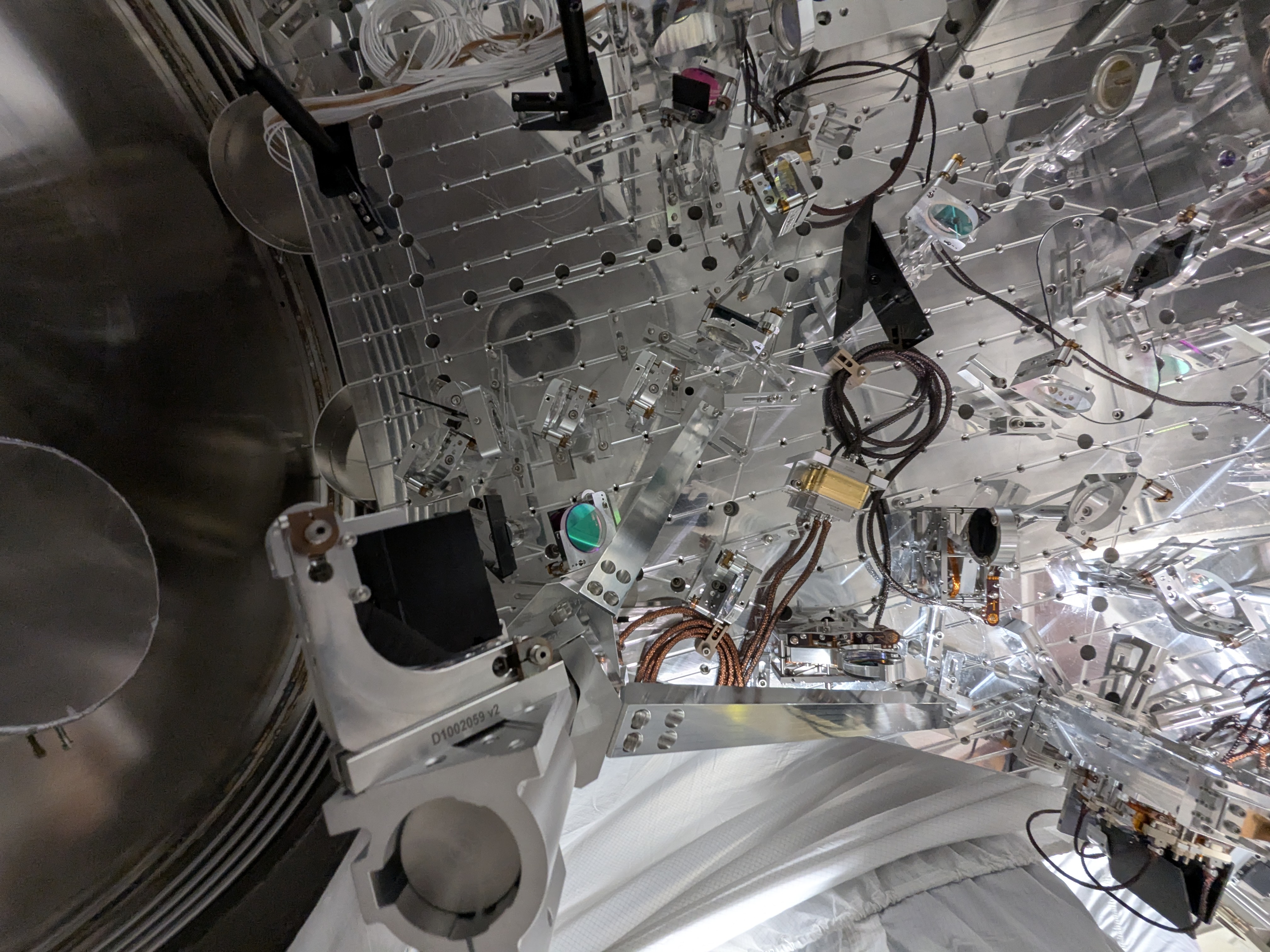
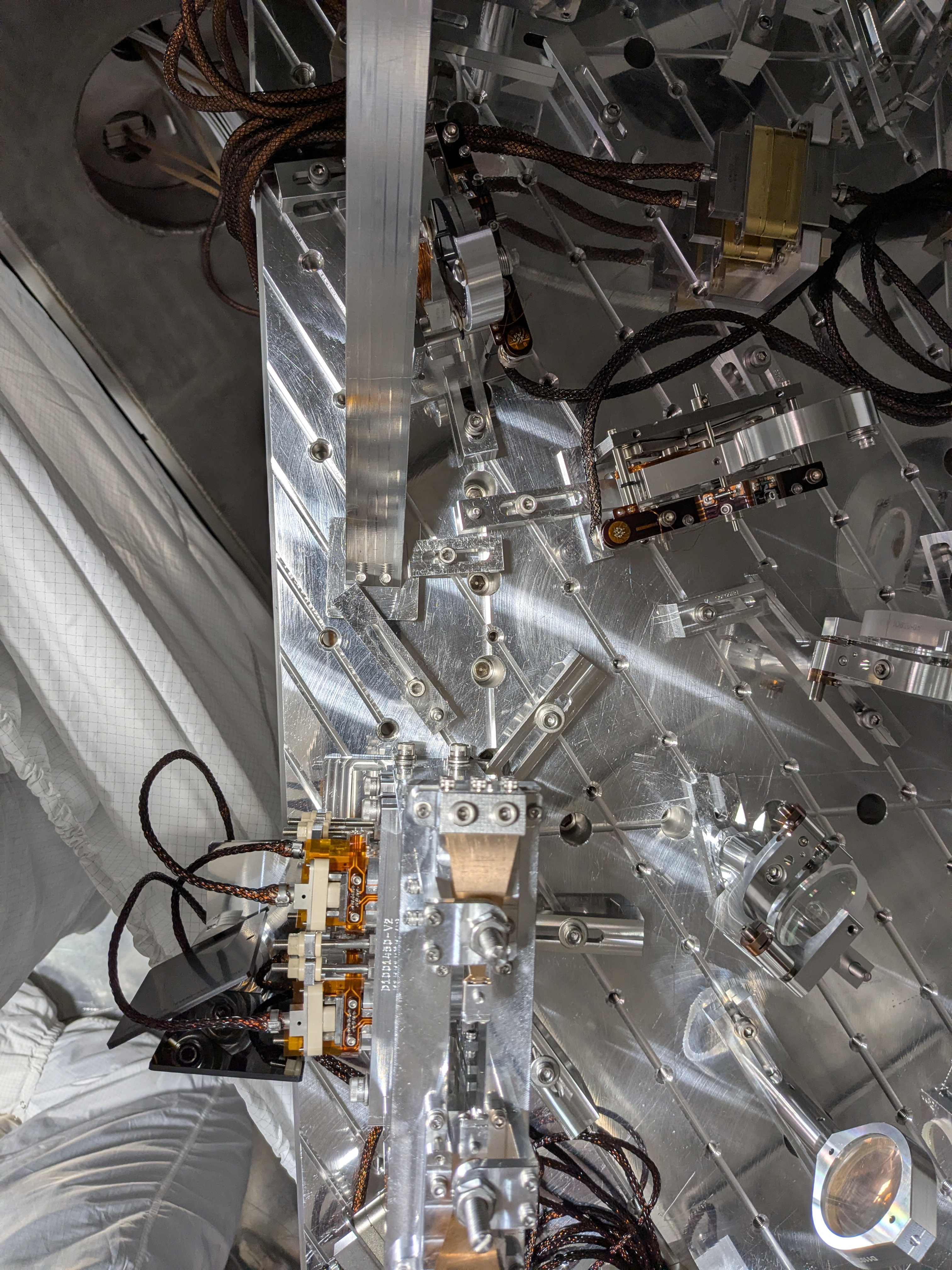
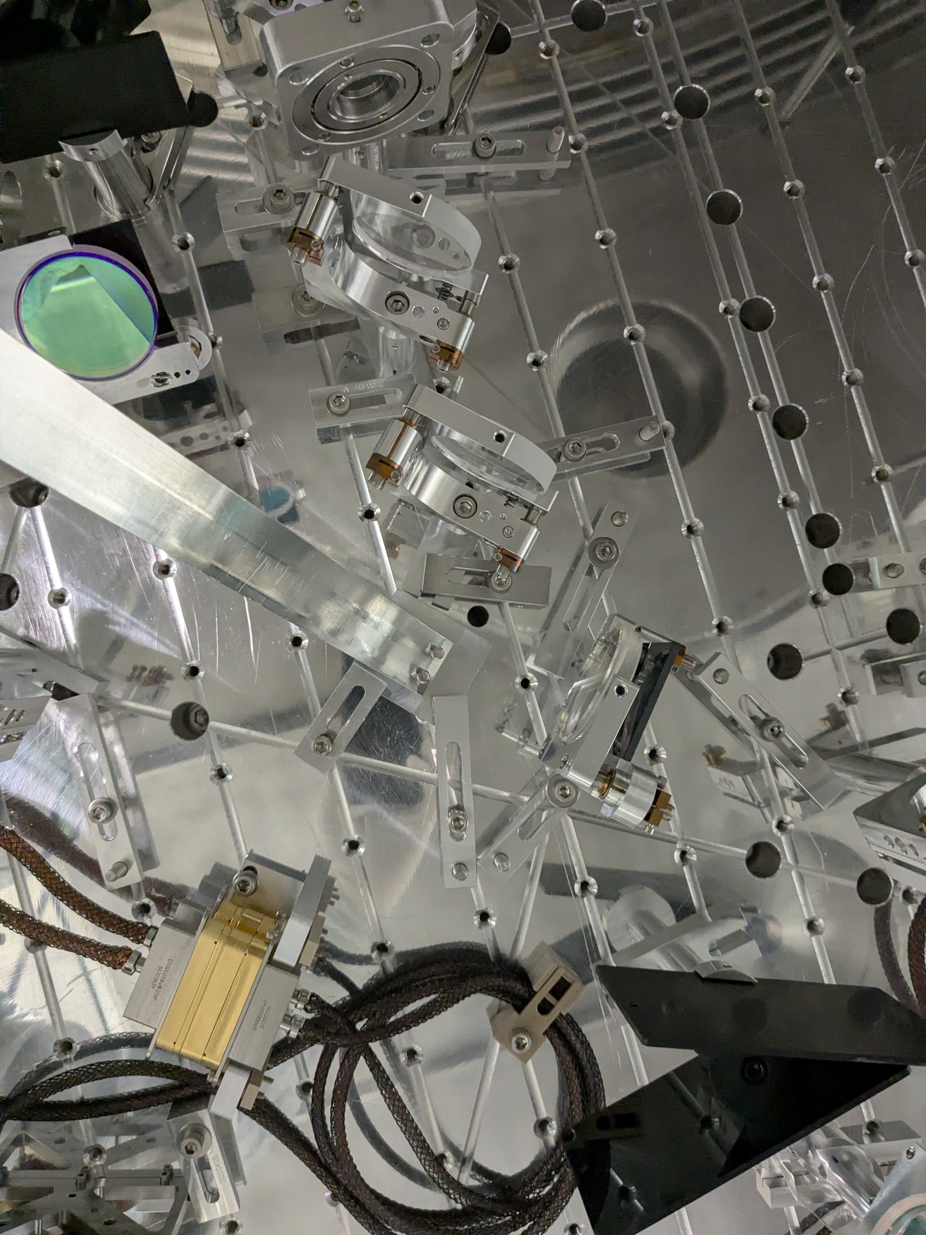
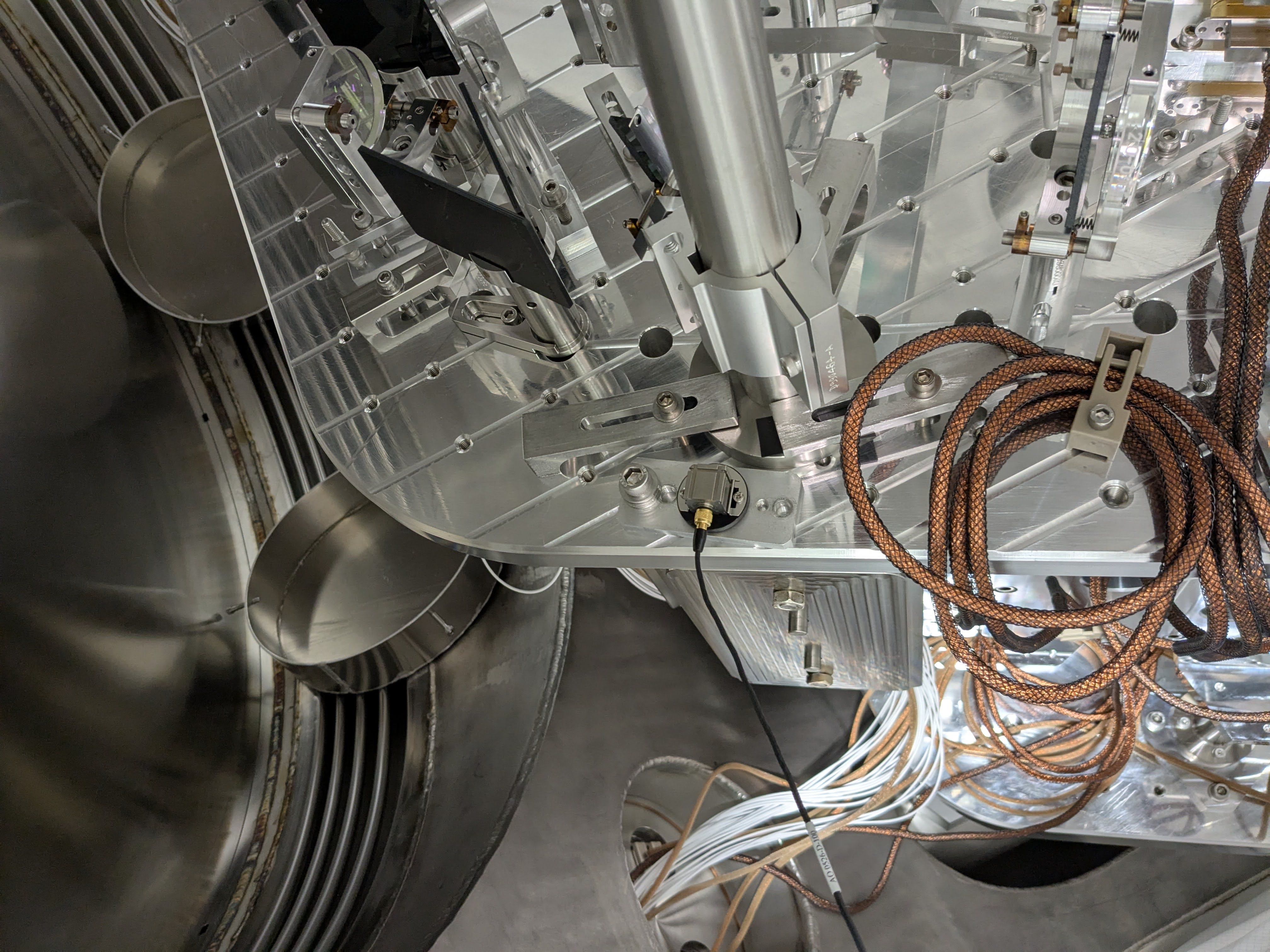
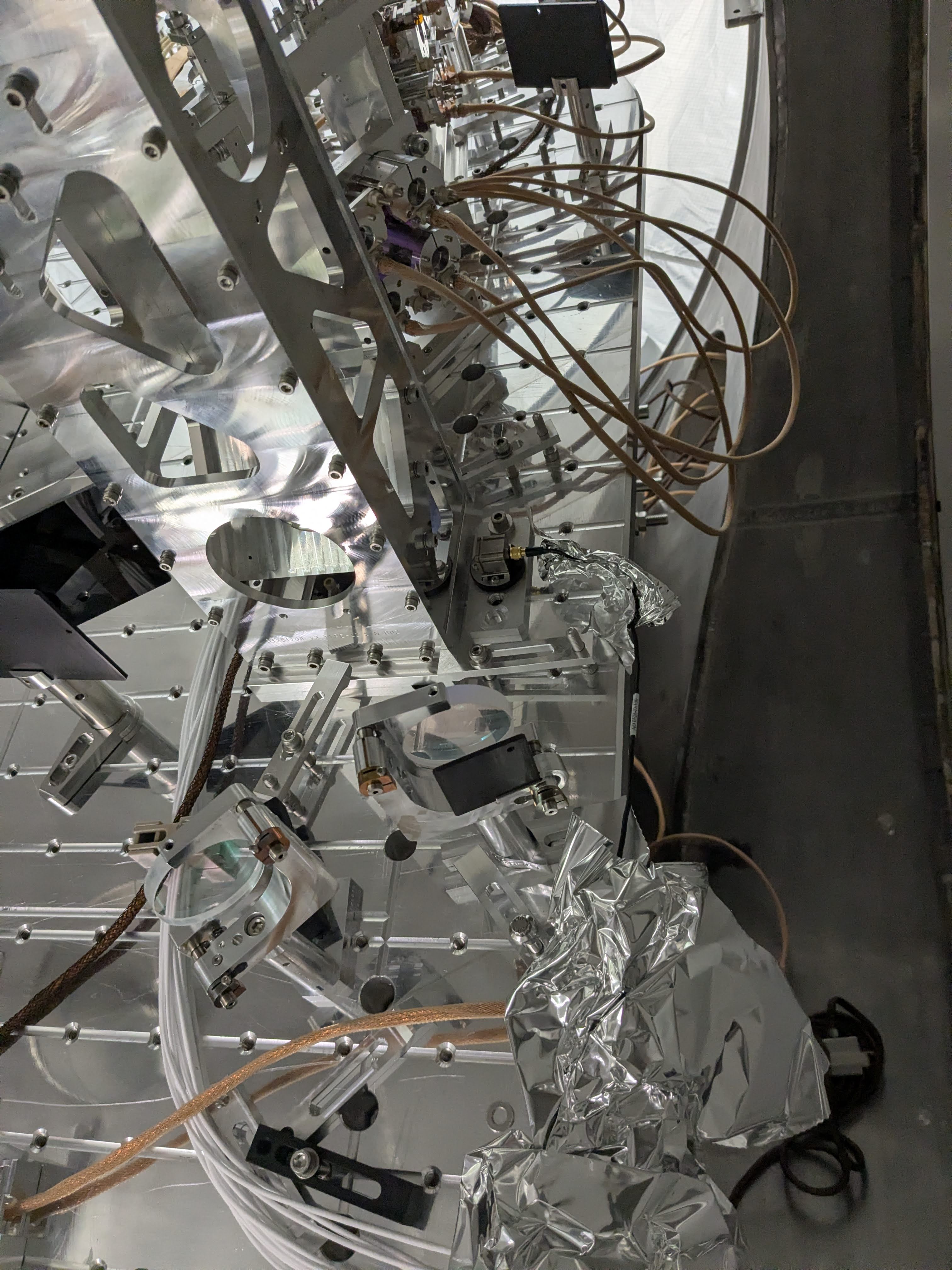
We have intalled the POP periscope stiffener.
Some dog clamps in the REFL path as well as the cable bracket for PM1 were relocated to accomodate. 1st and 2nd picture are "before" photo. 3rd one is after PM1 cable bracket relocation but before installing the stiffener. There are also three "after" photos showing how things look on the table.
POP beam clearance:
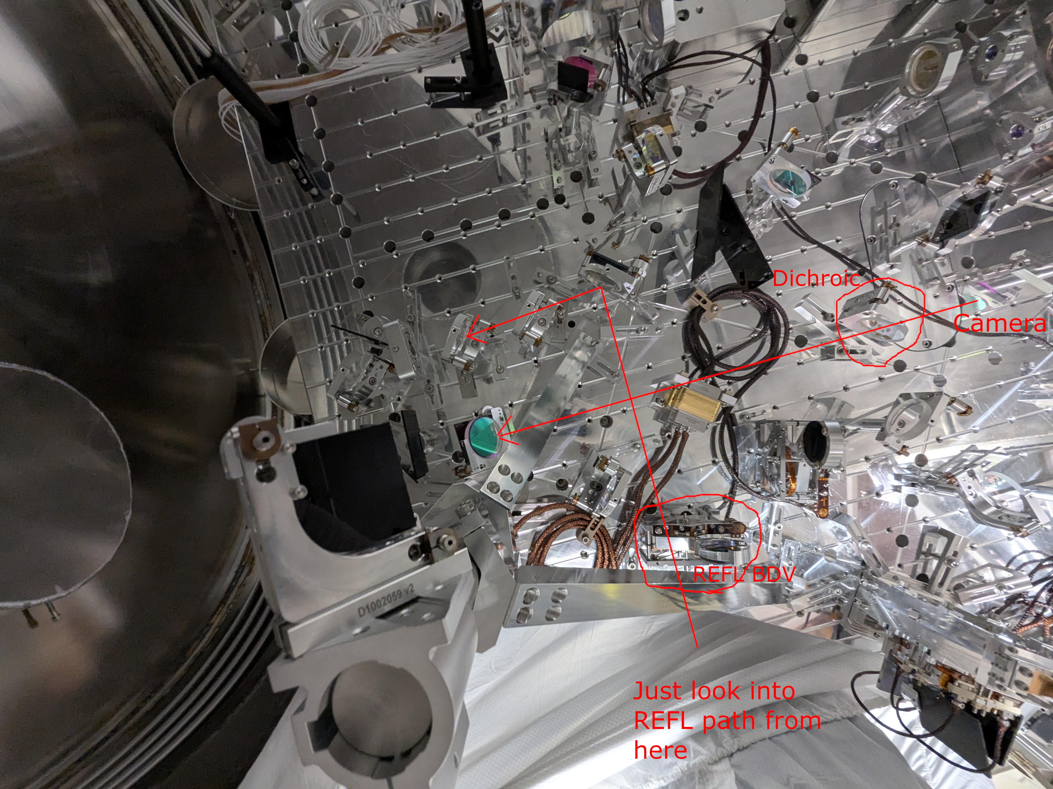
I took the picture of the bottom periscope mirror through dichroic (HR for IR, transmission for green) to see the beam clearance. In the first such photo (POP_beam_clearance.jpg), the camera is close to the center of the dichroic and the short stiffener beam is close to the edge of the optic but not occulting the mirror, so we're OK. Just to make sure that we're absolutely safe, I moved the camera closer to the -Y edge (right on the picture) of the dichroic (POP_beam_clearance_extreme.jpg) and it still looks OK.
If it's hard to understand what was done, look at the annotated photo (the last attachment After_stiffener_installed_annotated.jpg), the cellphone camera was inserted to "Camera" position.
REFL beam path:
I confirmed that the long stiffener beam doesn't interfere with the motion of the REFL beam diverter. Also, when the REFL beam diverter is open, I looked into the last steering mirror for the REFL air path from the viewport position to make sure that the short stiffener beam won't occult the REFL path.
Some hiccups:
We used D2500433 -11 variant S/N 4 and -1 variant S/N1 even though page 11 of T2500339 suggests it should be -10 and -2 variant, respectively. We didn't have -10 variant, and -2 variant was absolutely too short.
B&K
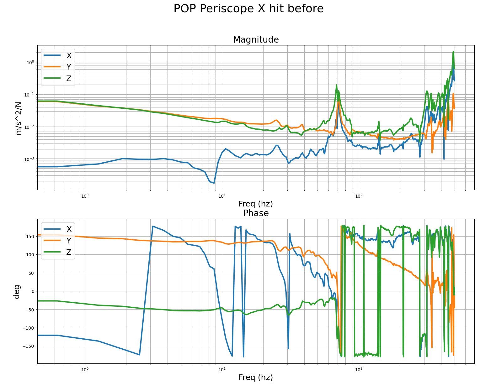
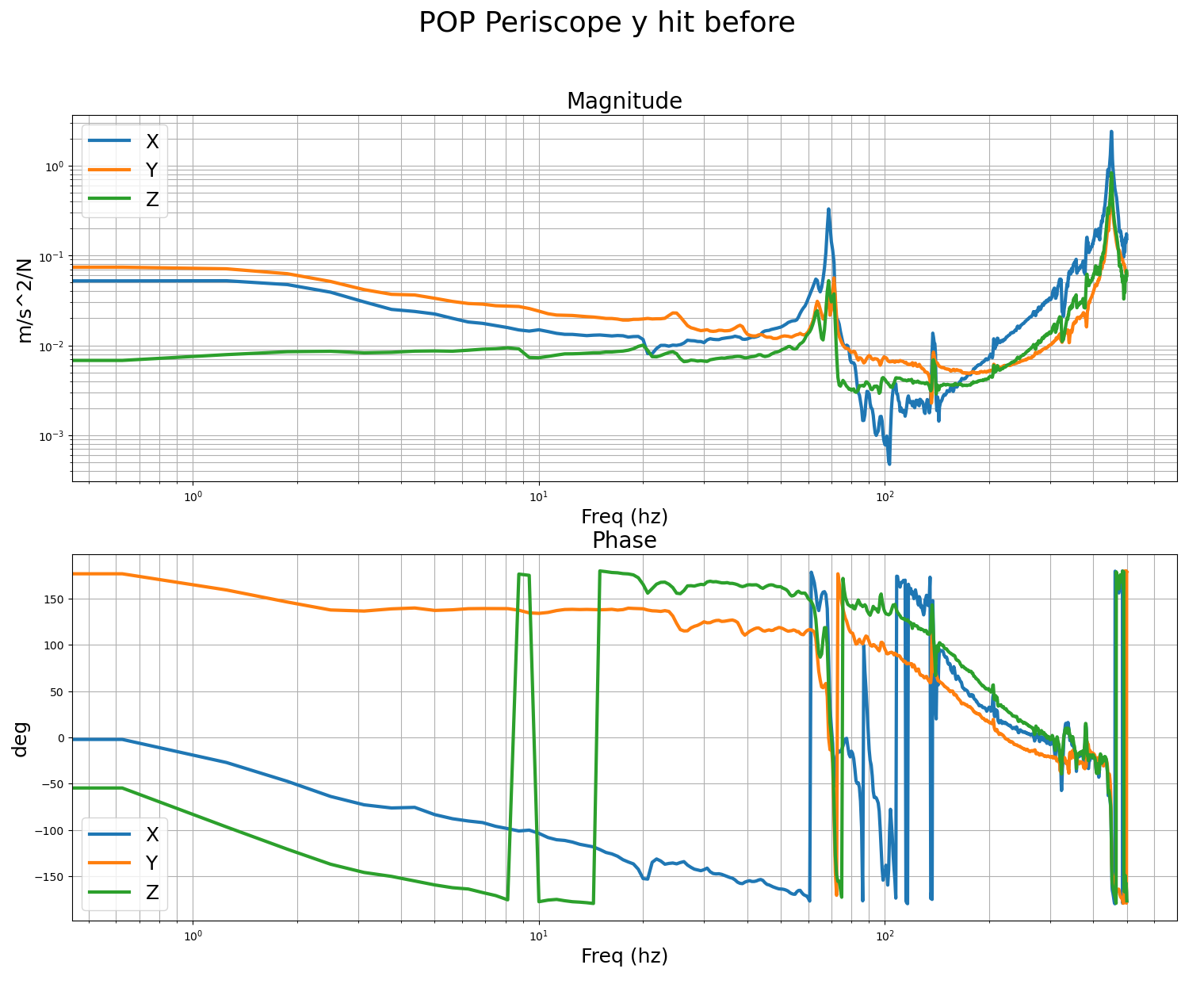
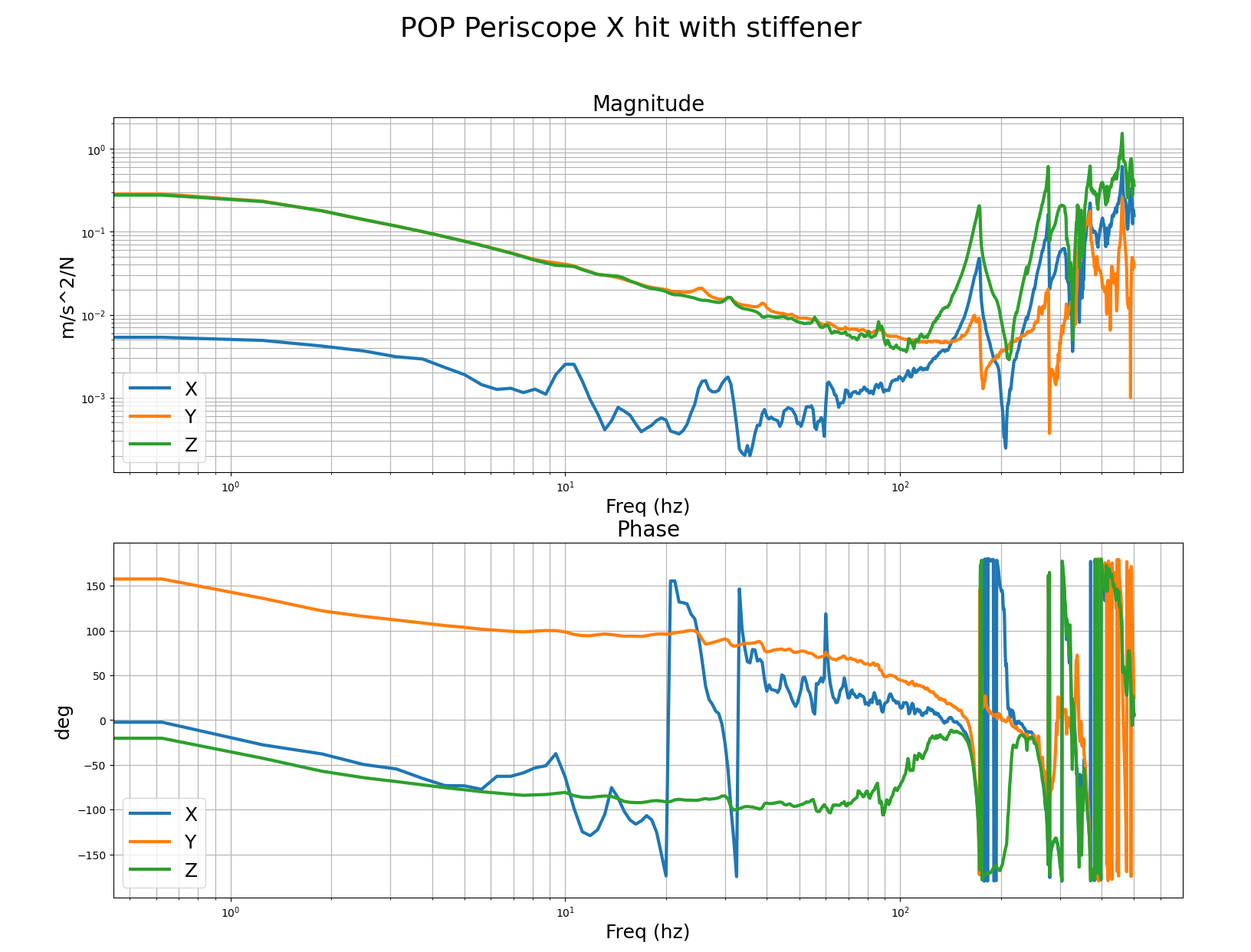
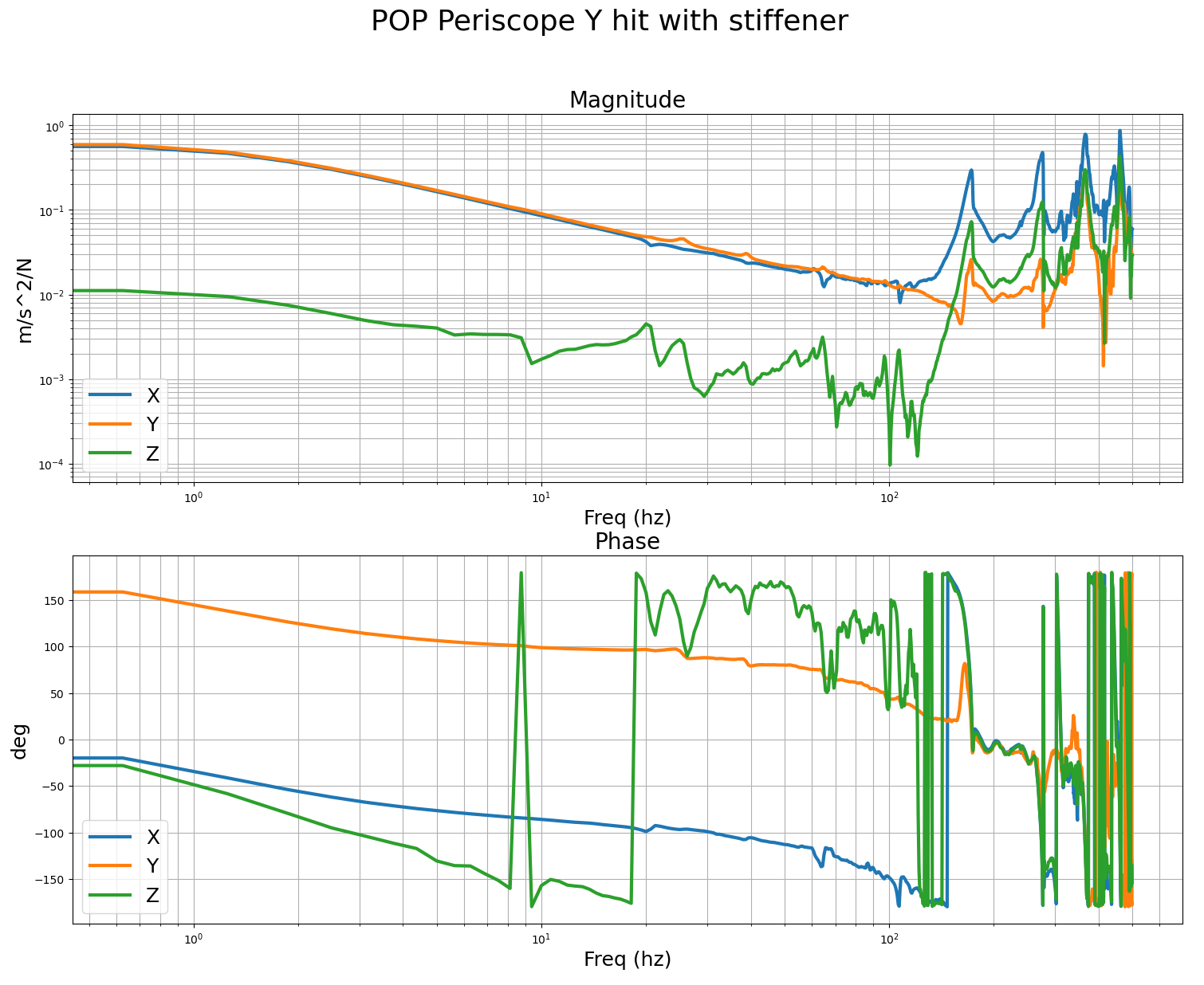
We performed B&K hammer measurements before/after the stiffener installation for POP periscope. Before, there was a 70Hz-ish peak. After, it was pushed higher up in frequency. The transducer was attached to the ISI table and Jim hammered the top of the periscope.
Likewise we did B&K test for the input periscope of the JAC even though it was not absolutely necessary.
We haven't done B&K for the JAC output periscope because it's not even fully clamped down (we will move it).
Jim will post the data.
Unused stiffener parts are in my office for now.
Tagging EPO for photos.
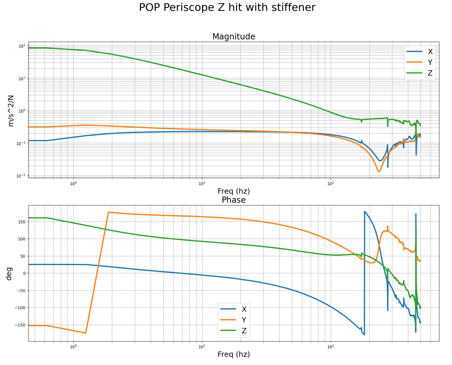
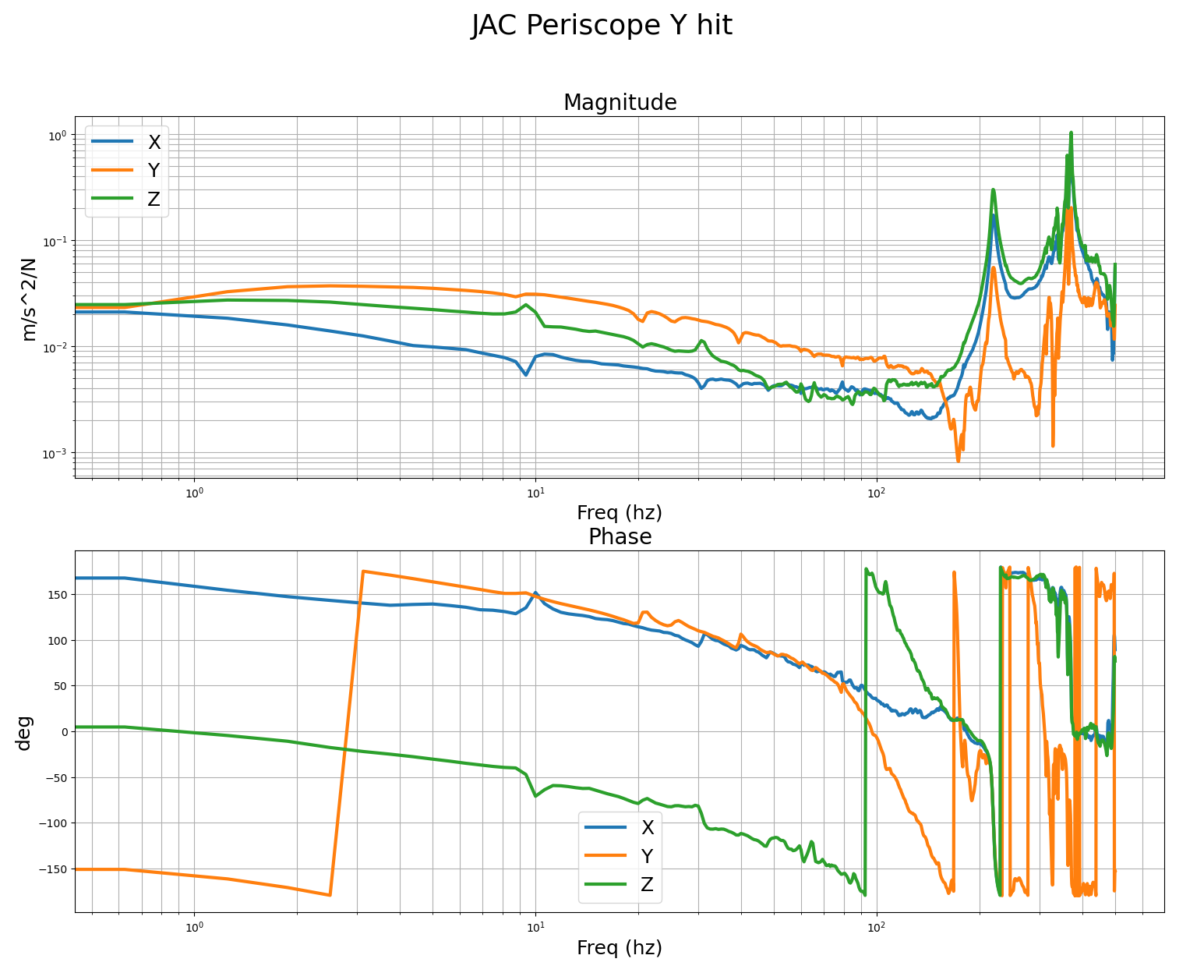
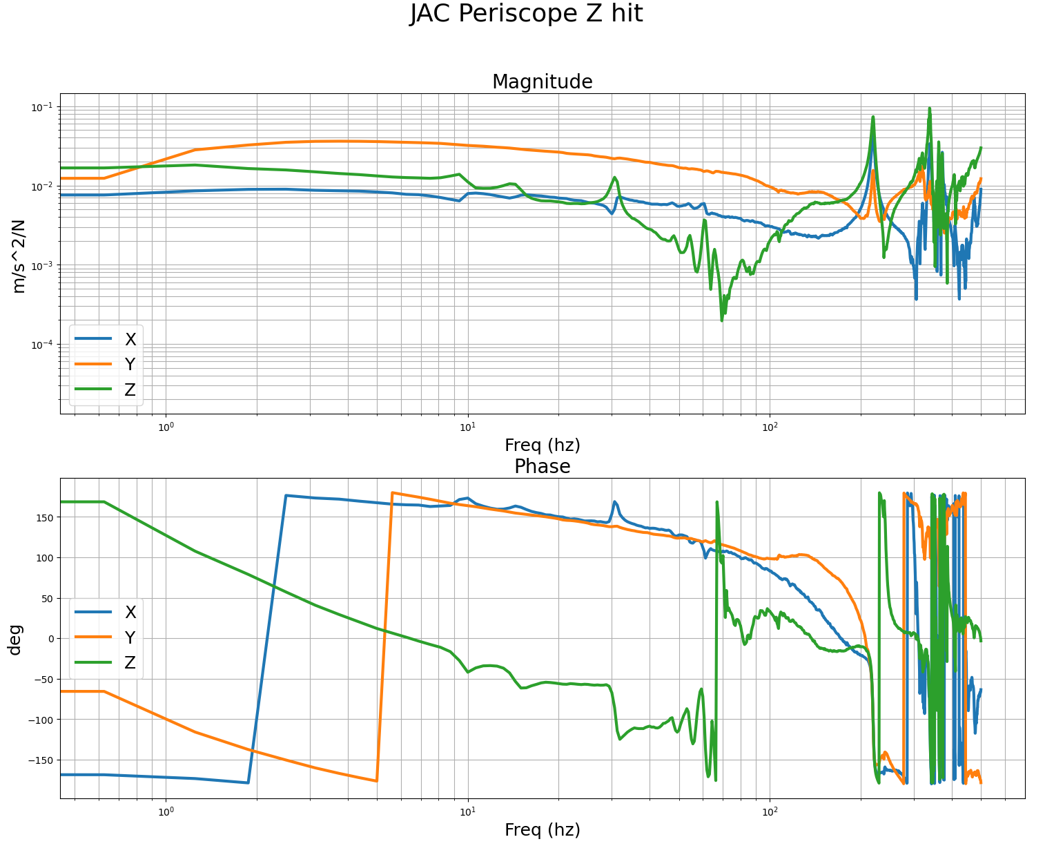
These are the measurements we got with the B&K of the POP periscope before and after adding the stiffener. For the POP periscope, we mounted the accel to the table, right at the foot of the periscope, and did the impacts at the top of the post. The accelerometer was mounted with the sensors Z aligned vertically, the Y axis was roughly parallel to the edge of the ISI, so it was mostly pointing along the IFO X arm. First and second images are impacts in the IFO X and Y dofs, you can pretty clearly see the 70hz post resonance. Third, fourth and fifth images are with the accelerometer in the same spot after adding the stiffener, it seems the mode has successfully been moved much higher to around 170hz. This should allow me to increase the ugf and loop gain quite a bit, to be more like the other ISI. I'll verify with tfs on the ISI after the vent.
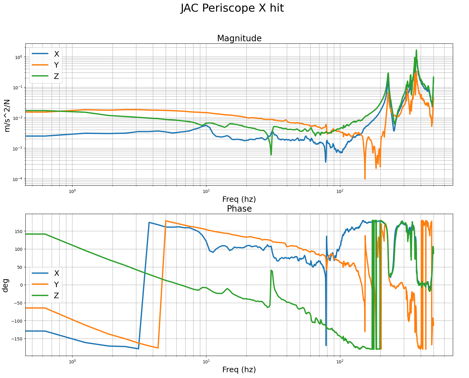
Last 3 images are B&K measurements of the JAC periscope, accel for these measurements was mounted on the edge of the table, with x,y,z sensor dofs aligned to the IFO x,y,z dofs. This also looks pretty good, first features are over 200hz.
Attached zip contains the csv data exports of each of the measurements. Names indicate the direction of the hit with the hammer, relative to IFO x,y,z conventions.
As per Jeff's request we took osme zoomed out photos of the periscope today.


TITLE: 01/21 Day Shift: 1530-0030 UTC (0730-1630 PST), all times posted in UTC
STATE of H1: Planned Engineering
INCOMING OPERATOR: None
SHIFT SUMMARY: Continued alignment for HAM7, and BNK measurements on HAM1 periscopes. Currently the LVEA is LASER HAZARD
LOG:
| Start Time | System | Name | Location | Lazer_Haz | Task | Time End |
|---|---|---|---|---|---|---|
| 15:37 | FAC | Randy | LVEA | n | Craning rails (started at 15:15) | 16:09 |
| 15:37 | FAC | Nellie | LVEA | n | Tech clean | 16:21 |
| 16:11 | FAC | Randy, Corey | LVEA | YES | Craning | 17:23 |
| 16:31 | VAC | Travis | MX, EX | n | Turbo pump tests | 21:10 |
| 16:35 | SQZ | Sheila | LVEA | YES | HAM7 alignment | 19:43 |
| 16:51 | FAC | Nellie | LVEA | YES | Tech clean | 17:30 |
| 16:57 | TCS | Matt | JOAT Lab | n | Building up second table | 19:21 |
| 17:17 | SEI | Jim, Keita | LVEA | YES | BNK | 19:52 |
| 17:23 | PEM | Robert | LVEA | YES | Mounting accelerometers | 18:53 |
| 17:37 | SQZ | KarMeng | LVEA | YES | HAM7 alignment | 19:43 |
| 17:37 | SAF | LVEA IS LASER HAZARD | LVEA | YES | LVEA IS LASER HAZARD | 20:30 |
| 17:46 | FAC | Randy, Corey | LVEA | YES | Craning | 19:00 |
| 18:09 | Matt | LVEA | YES | Grabbing laptop | 18:26 | |
| 18:13 | VAC | Jordan | MY, EY | n | Turbo pump tests | 22:04 |
| 19:04 | SEI | Rahul | LVEA | YES | Helping Jim | 19:24 |
| 19:17 | PCAL | Tony | PCAL Lab | y(local) | Getting ready for a measurement | 19:24 |
| 19:22 | FIT | Matt | YARM | n | Running | 20:30 |
| 19:43 | SAF | Corey | LVEA | YES | Transitioning to Laser SAFE | 20:03 |
| 20:09 | EPO | Mike, Rana, tour | LVEA | n | Tour | 21:09 |
| 20:33 | EE | Fil | LVEA | YES | Cabling | 00:17 |
| 20:41 | FAC | Randy | LVEA | n | Securing railing | 21:09 |
| 21:10 | SAF | Tony | LVEA | YES | Transitioning to laser HAZARD | 21:28 |
| 21:12 | SQZ | Sheila, KarMeng | LVEA | YES | HAM7 alignment | 22:34 |
| 21:40 | FAC | Tyler | LVEA, MX, MY | YES | 3IFO checks | 23:40 |
| 21:52 | VAC | Travis | Optics Lab | n | Grabbing tool | 21:58 |
| 22:08 | JAC | Jason | LVEA | YES | Parts hunting and FARO spot hunting | 22:31 |
| 22:46 | PCAL | Tony | PCAL Lab | y(local) | Finding case for beamsplitter | 23:17 |
| 22:49 | PEM | Robert | LVEA | YES | Mounting accelerometers | ongoing |
| 22:49 | SAF | LVEA IS LASER HAZARD | LVEA | YES | LVEA IS LASER HAZARD | ongoing |
| 22:50 | JAC | Jason, Jennie | Optics Lab | n | Hunting for parts | 23:02 |
| 00:18 | SEI | Jim, Keita | LVEA | YES | BNK measurements | 00:20 |
[Sheila, Karmeng]
FC1 alignment was adjusted to account for the buoyancy, and we coaligned the FC1 green/IR beam. We managed to recover the FC refl green on SQZT7 periscope, but not on the photodiode.
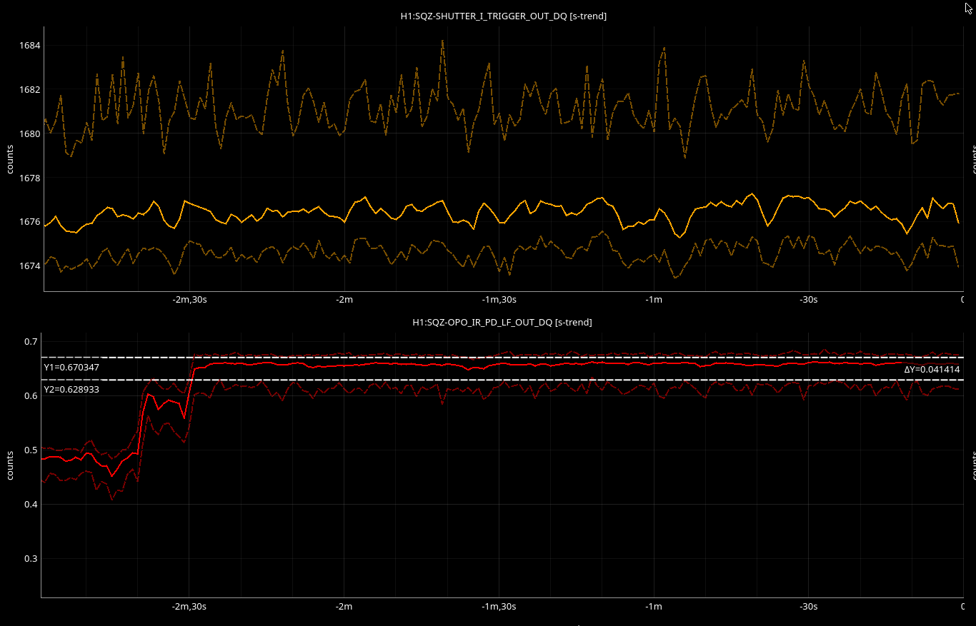
The OPO IR transmission is misaligned, and we managed to recover the IR on SQZT7 PD. As we recovered the IR refl (top) on SQZT7, we saw an improvement from ~600 to ~1680 (we may have been clipping on the refl PD previously).
By changing the setting on ZM2, we managed to improve the IR trans (bottom).
Old setting ZM2 PIT: 424 ; YAW: -235
New setting ZM2 PIT: 444 ; YAW: -315
Will need to check on the iris tomorrow, to make sure we did not deviate from the original path.
Some additional information:
In december we checked that the alignment sliders on FC1 had not moved since the observing run. Noting that the red and green co-alignment were off, this morning I trended osems as well and saw that FC1 had a shift of +200urad in pitch at the time of the vent. The ZMs all had similar shifts. When I moved FC1 to make sure the osem values matched the observing run pitch, the beam was then clipped on B:P1. We adjusted B:M1 to clear the VIP, then adjusted B:M4 to recenter the beam on the ZM4 iris. Then Kar Meng adjusted ZM4 alignment to match the irises on SQZT7 in the homodyne path. After this we saw that the beams were still on the QPDs in HAM6, but not well centered. We will have to return to that tomorow.
After that we turned our attention to the co-alignment of the FC green sensing with the squeezed beam. The shift in the FC1 pitch wasn't enough to make a difference in the large misalingment of these two. We became confused for a while looking at the FC green beam in the SK path. The old HAM7 layout shows the SK path on the -X side of the three beams leaving the chamber toward the green periscope, this is correct but the two beams cross as they travel down the periscope so that the FC green refl path is on the -X side by the time it reaches the bottom, and looking at the SQZT7 layout shows the SK path located on the table in the area where the FC green refl path is.
Once we understood this path, we were able to walk H:M1 to coalign red and green right after A:DC2, and using H:M2 to co-align them at the iris after ZM3. Then we adjusted the pointing to the periscope using H:M4.
While we were in laser safe, I unlocked the OPO suspension, since we hope that we are finished with the alignment work on the VIP. This caused enough of a shift that the reflected seed beam was clipping on its way to the diode, perhaps on the lens in HAM7. We moved this beam so that it is still mis centered on the lens but not close to the edge.
(Corey Gray, Randy Thompson)
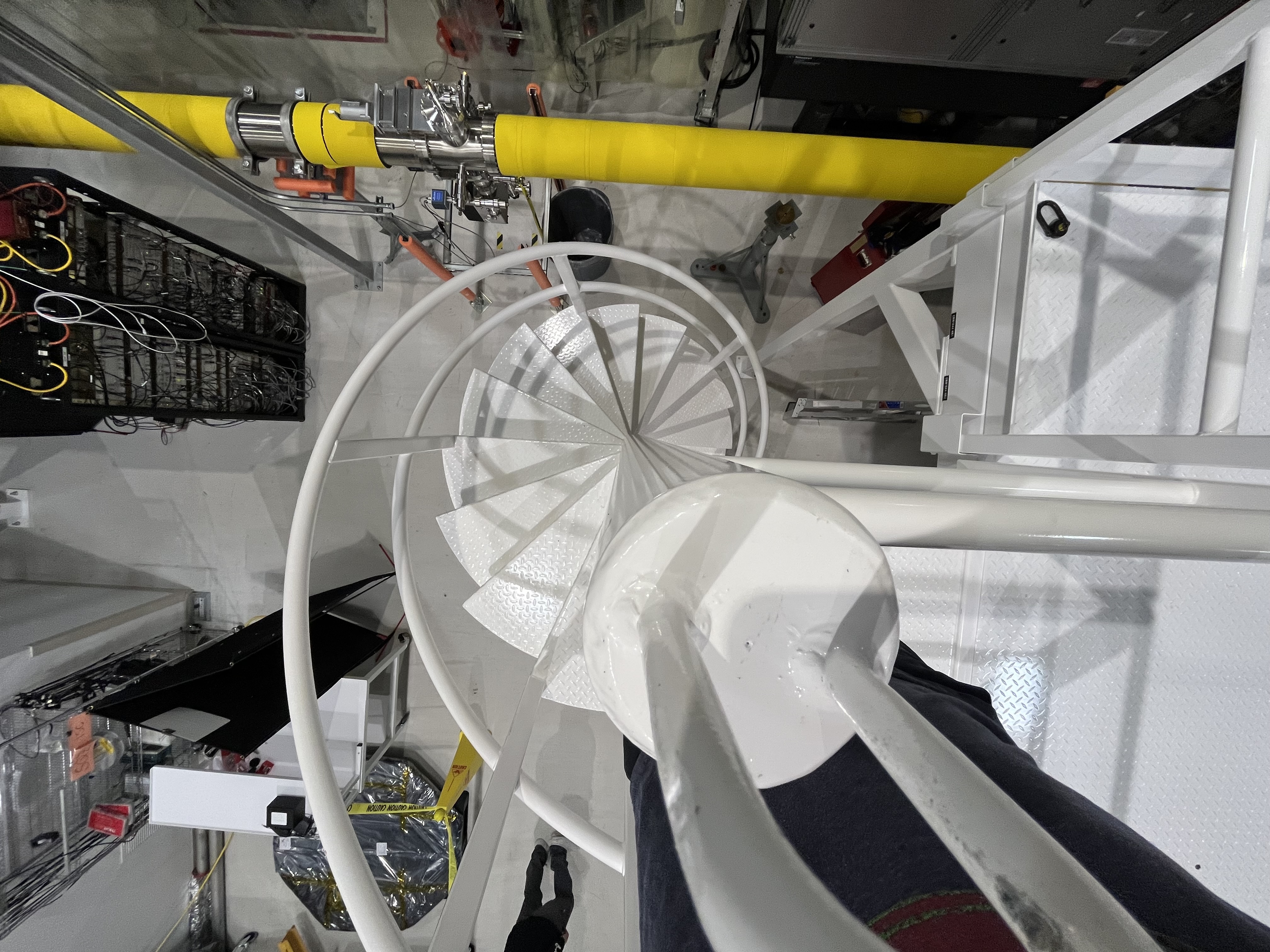
This morning (during mostly laser Hazard) I assisted Randy with work on the eMod Platform. The eMod platform is the elevated large work platform which is installed over the TCSx In-Air Table and next to BSC3. The eMod is an additional workspace to be used for the installation of the BBSS (Big BeamSplitter Suspension) into BSC2 in the coming months.
Today, we craned up handrails and installed them in place. After this we rolled the white powdercoated spiral staircase into the LVEA from the HiBay and then used the crane to position the stairs next to the eMod. The stairs were attached to the eMod floor via qty 3 long 3/8-16 bolts. (attached is a top-view photo of the installed stairs).
After this we cleaned up our area and then staged the new horizontal HEPA filter assembly which will be used later for the BBSS installation.
[Jennie, Jason, Rahul, Keita, Masayuki]
We have observed the light coming out from the HAM2 after the MC1 reflection.
This is the summary report for the optics alignment in HAM1 after the JAC.
An iris was placed and centered on the output beam from the JAC before installing the L1 lens. The lens was then installed such that the beam remained centered on the iris.
JM2
This optic will need to be repositioned after the EOM is installed. Therefore, we placed it without fine adjustment for now. The angular alignment was done using an iris located at the position where the HR surface of JM3 will be. Notes for final installation:
The barrel must be cleaned before final installation.
A beam dump must be installed behind the mirror.
JM3
Although JM3 also needs to be swapped to tip-tilt, the beam reflected from JM3 serves as the alignment reference after the EOM. Therefore, we performed careful alignment. An iris was placed at the planned location of JAC_M3, and the beam was centered on it by adjusting JM3.
JAC_L2, JAC_L3
The two lenses were then installed. They were centered using the same iris that had been used for the JM3 alignment.
JAC_M3
The angle of the reflected beam from JAC_M3 is critical, as it determines the polarization mismatch caused by the periscope’s rotation. An iris was placed at the output beam hole, and the beam was aligned parallel to the hole line. Previous measurements confirm that the input beam axis to the IMC in HAM1 is parallel to the hole within ~1 mrad ([link]). Therefore, this alignment ensures that the polarization mismatch remains within acceptable limits.
Periscope (initial alignment attempts)
Initial alignment of the periscope was performed using the first iris (IR1) placed prior to installation.
Since the incoming beam was horizontal and parallel to the hole line, we expected the output beam to be rotated by exactly 90° and remain horizontal through the hole. After centering the beam on the iris by eye, we checked from the HAM2 viewport but did not observe the beam.
We attempted minor adjustments to the periscope, JM2, and JAC_M3. Some scattered light was eventually seen at the output periscope of the HAM2 IMC reflection path. However, IR camera footage from Keita showed that the focus did not match, and the light was deemed irrelevant. The detail can be found in Keita's alog.
Periscope (refined alignment)
On the following day, a second iris (IR2) was introduced to further constrain the horizontal alignment. This iris was placed approximately at the same height as IR1 and roughly aligned parallel to the hole line. The periscope was then re-aligned to pass through both irises.
From the POP septum window, we confirmed that the HAM2 periscope was visible and used it for alignment. Using an IR viewer, the beam was observed to hit the upper-left (10 o’clock) corner of the periscope structure. We switched to aligning JM2 and JAC_M3 using the top periscope mirror and IR1 as references (IR2 was removed at this point).
To identify the beam spot, we intentionally misaligned the pitch to make the beam hit the upper part of the periscope structure. To avoid blocking the beam, the iris was temporarily removed (its location was marked with three dog clamps; one clamp was slightly loose but the offset was minor, ~1 mm).
While keeping the pitch misaligned, yaw centering was performed using JAC_M3. Once centered visually, the iris was replaced, and JM2 was used to center the beam through it.
Fortunately, JM2 and the periscope top mirror are located at similar opical position, so the beam position remained nearly unchanged on the periscope mirror. This beam walking converged in two iterations.
The iris was removed again, and the beam was swept from top to bottom of the top periscope mirror using JAC_M3. The mirror was then centered using the midpoint of this motion. The iris was replaced, and pitch alignment was re-checked using JM2, again requiring just two iterations.
At this stage, some faint beam was observed using the viewer through the viewport. Although it wasn’t visible on a card, adjusting JAC_M3 slightly allowed us to confirm beam output from HAM2.
Final Checks
Finally, the IR1 centering was confirmed, and IR2 was placed near the periscope to act as a reference.
When checking the beam on JAC_L3, we found that it was offset by about 5 mm in the yaw direction. Further alignment is likely needed.
The beam spot on the periscope mirror is not perfectly centered, but it is close enough that no adjustment to the top mirror is deemed necessary.
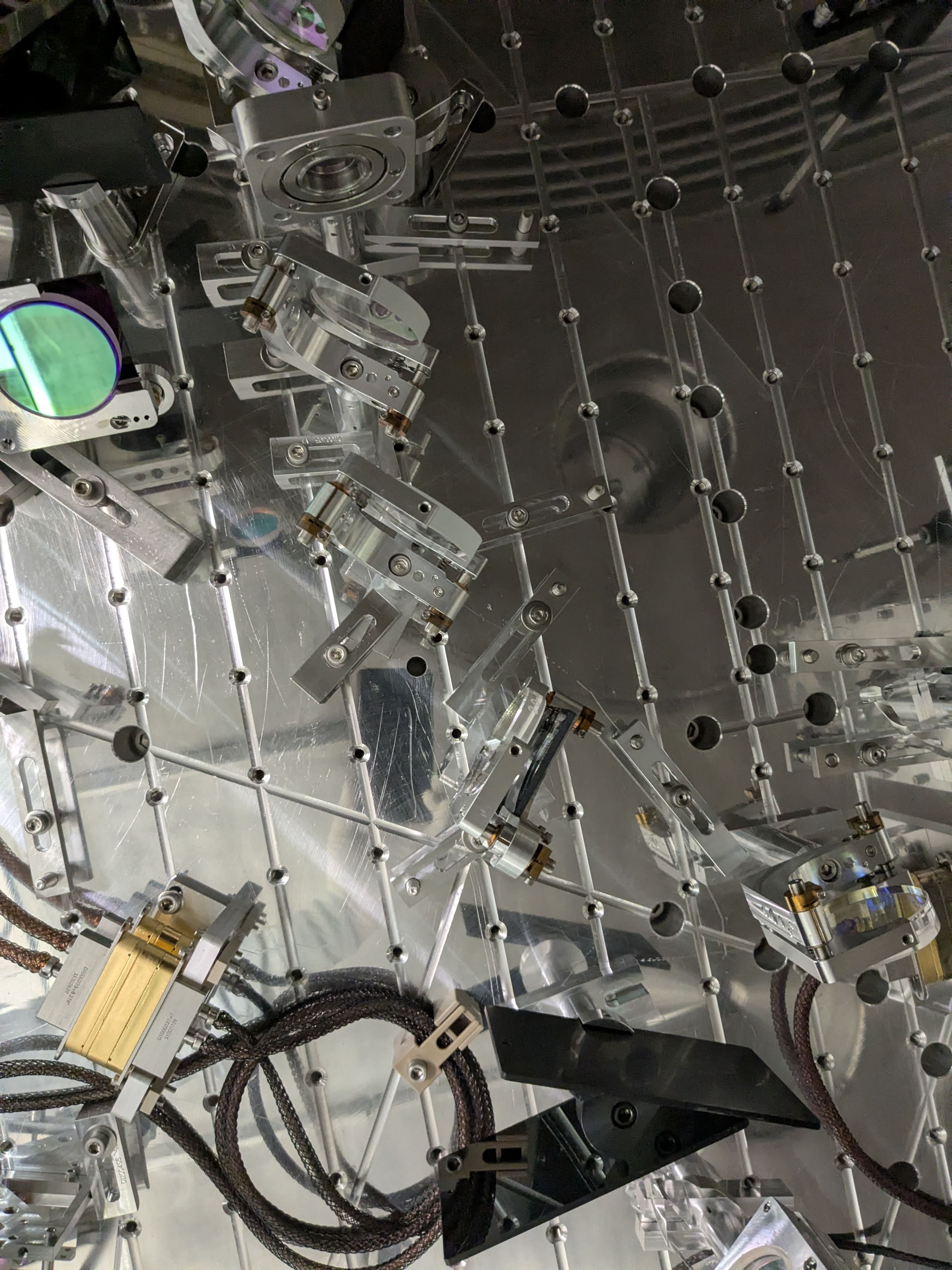
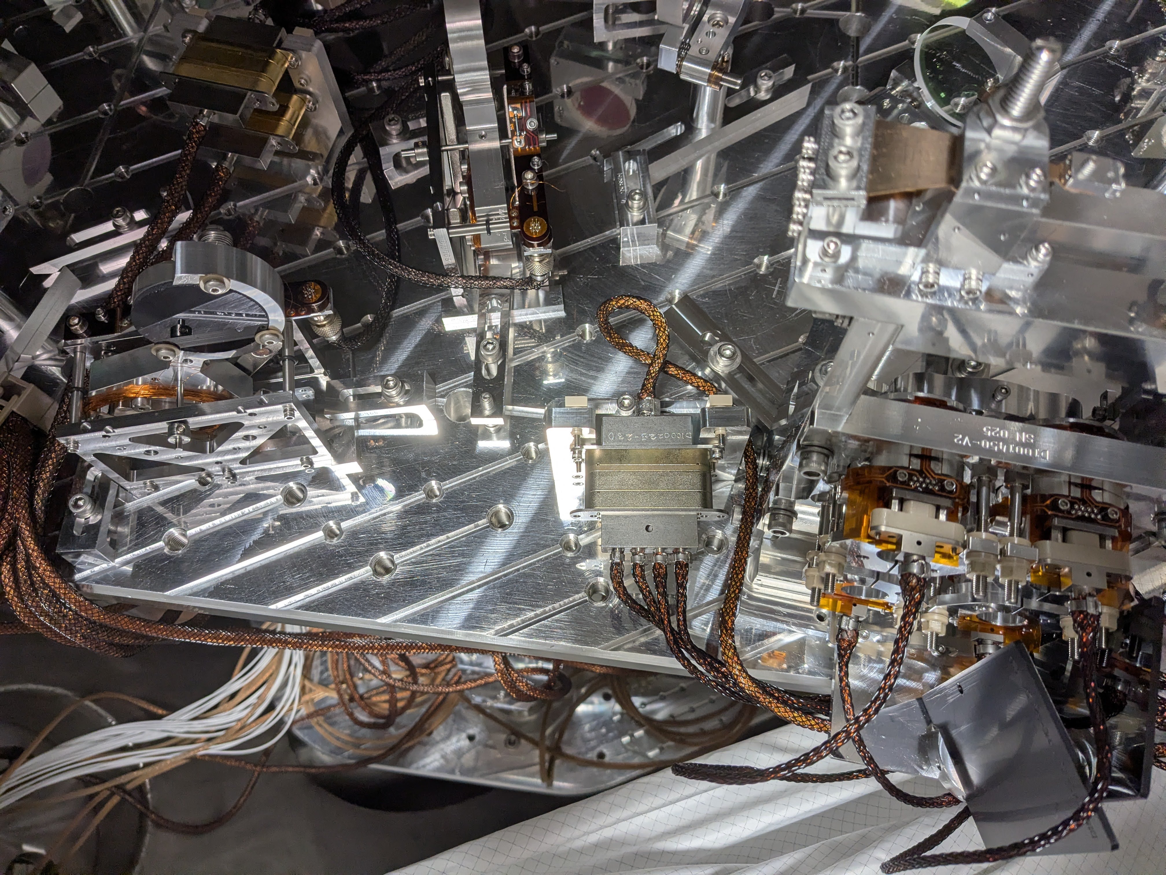
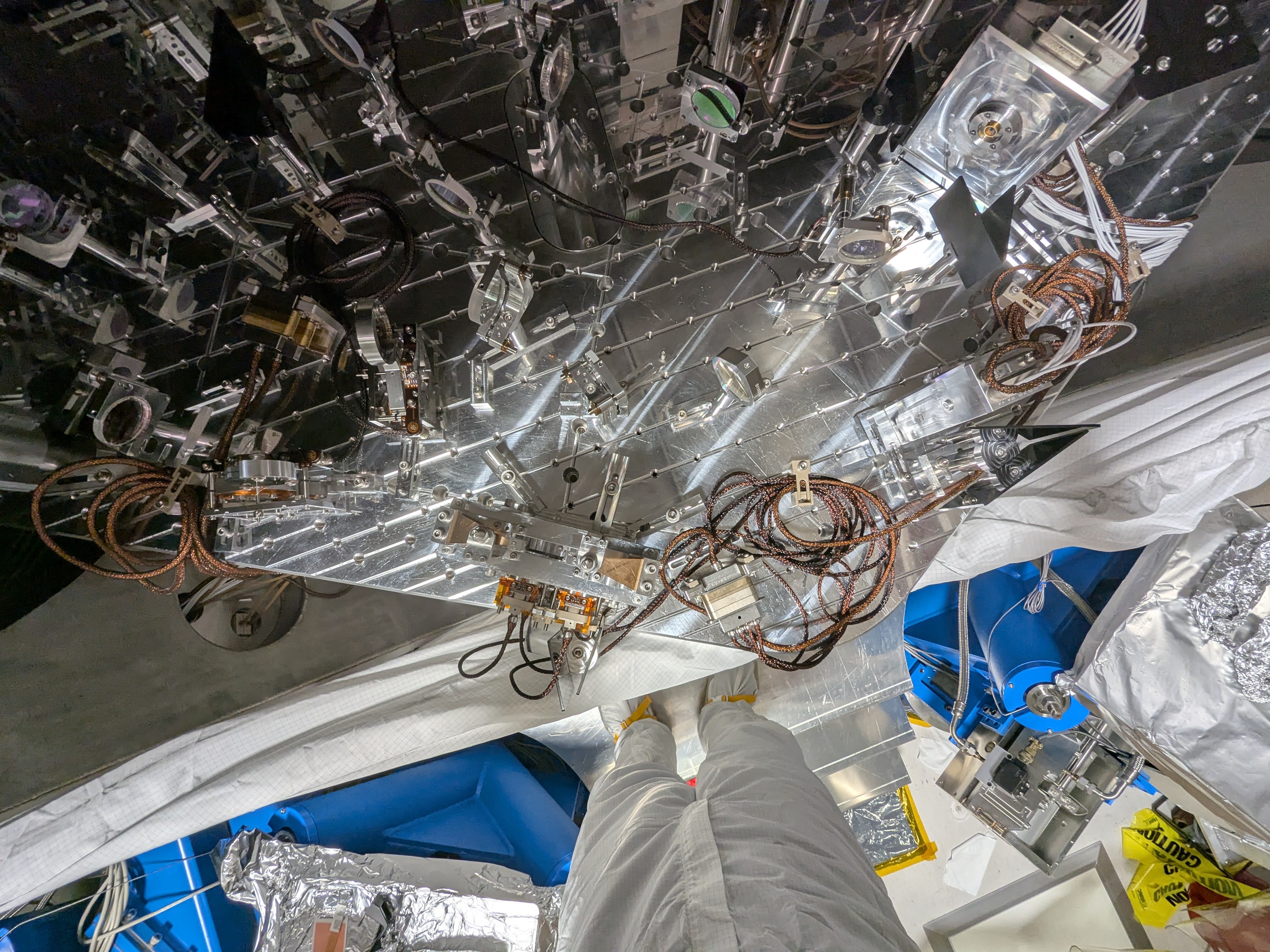
tagging for nice JAC team photo for EPO.
Pictures for posterity.


Sheila, Karmeng, Rahul
This morning we physically moved ZM4 (since the sliders were saturating the DAQ output) in YAW to better align it with ZM5 and ZM6. More details (including health check results) will be posted later.
ZM4 is now dogged down to its new position.
I ran a quick transfer functions on ZM4, a few things to note. The suspension is in air so I changed the Coil Driver state from 2 to 1 (reverted once I was done) as the wiki suggested, the ISI is also tripped but the damping was engaged on the suspension. We were also slightly shaking due to an 6.1 earthquake from near Japan.
The suspension is looking healthy.
/ligo/svncommon/SusSVN/sus/trunk/HXDS/H1/ZM4/SAGM1/Data/
2026-01-21_1700_H1SUSZM4_M1_WhiteNoise_L_0p01to50Hz.xml
2026-01-21_1700_H1SUSZM4_M1_WhiteNoise_P_0p01to50Hz.xml
2026-01-21_1700_H1SUSZM4_M1_WhiteNoise_Y_0p01to50Hz.xml


Betsy, RyanC, Rahul
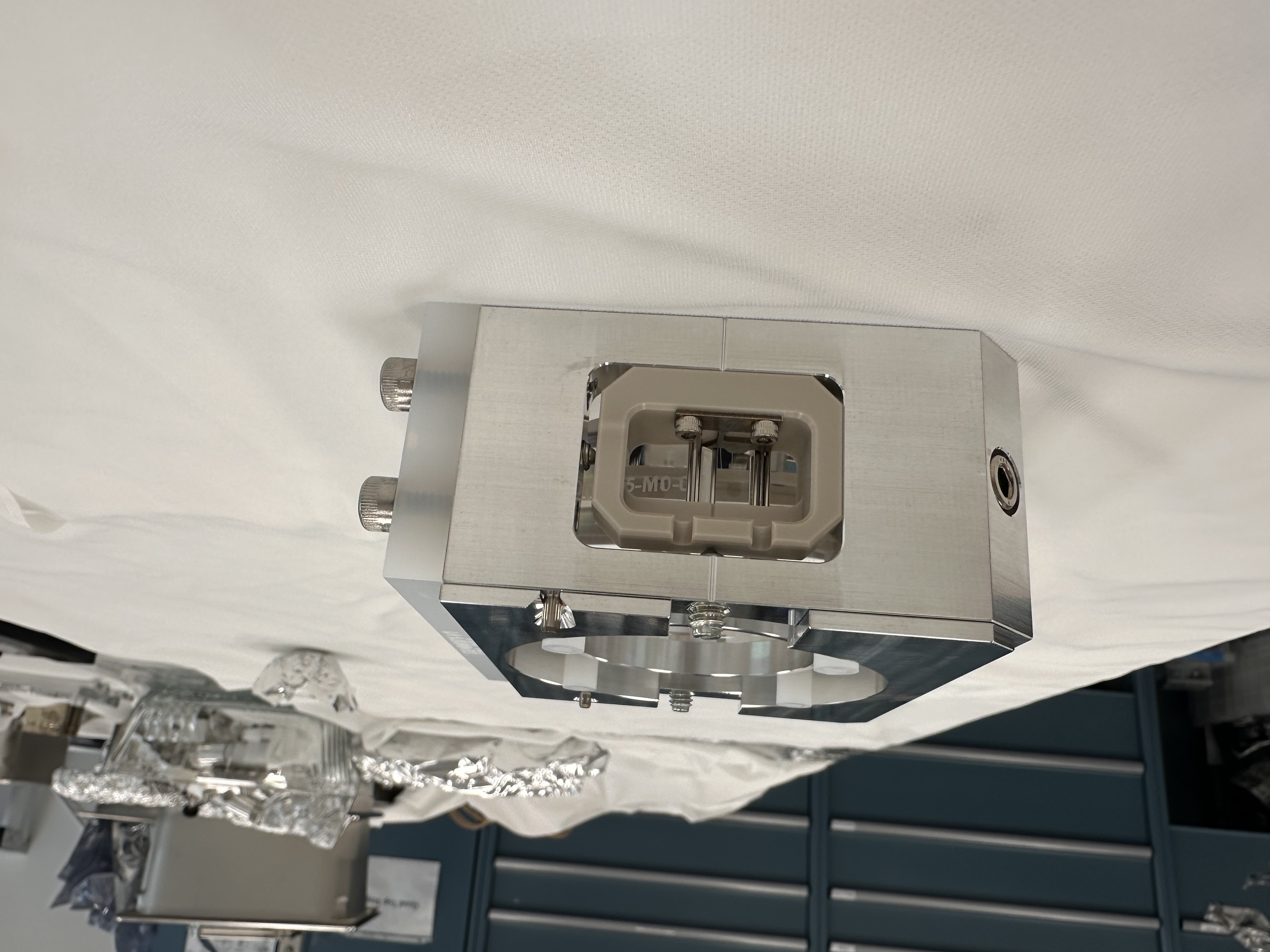
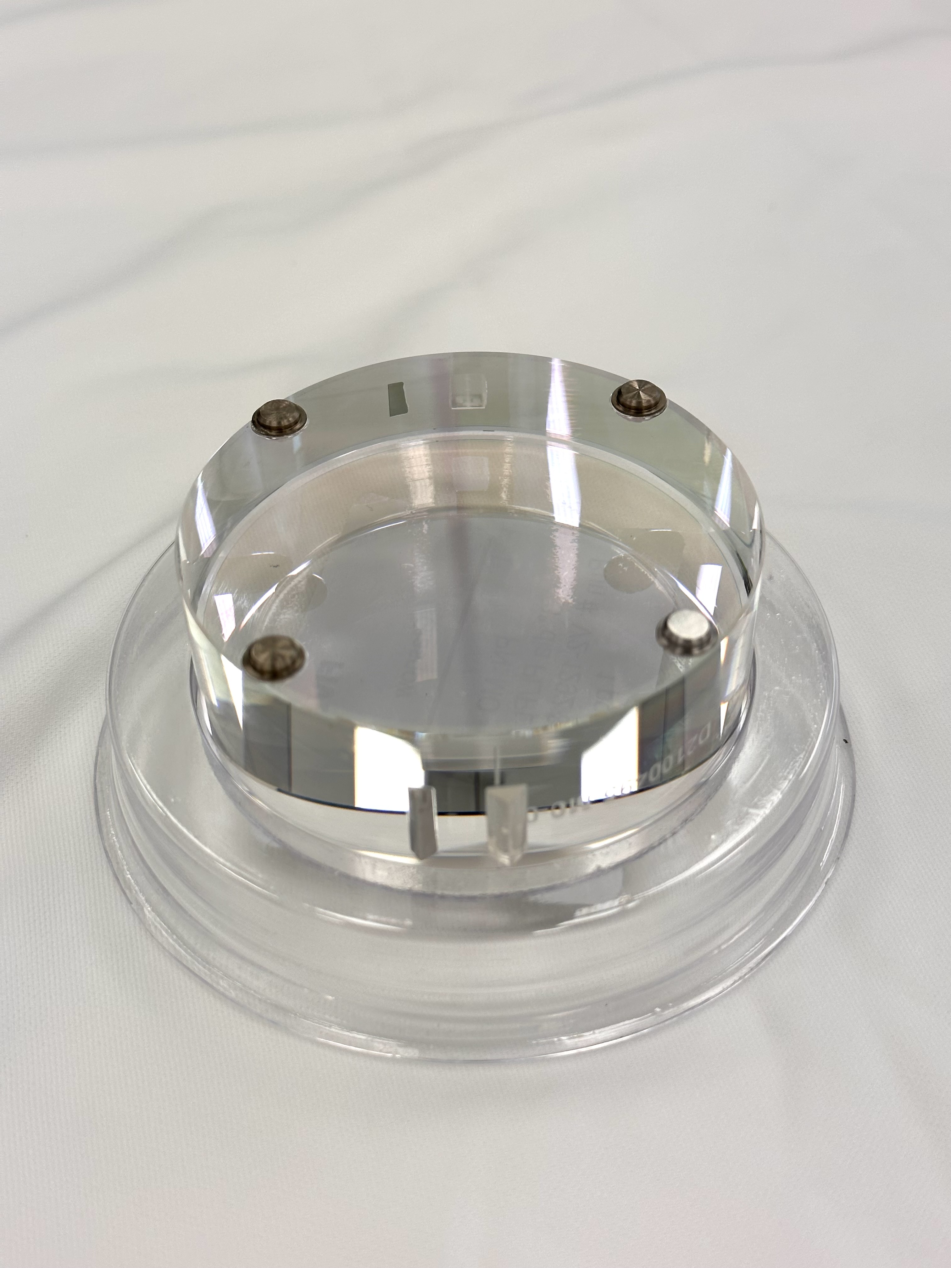
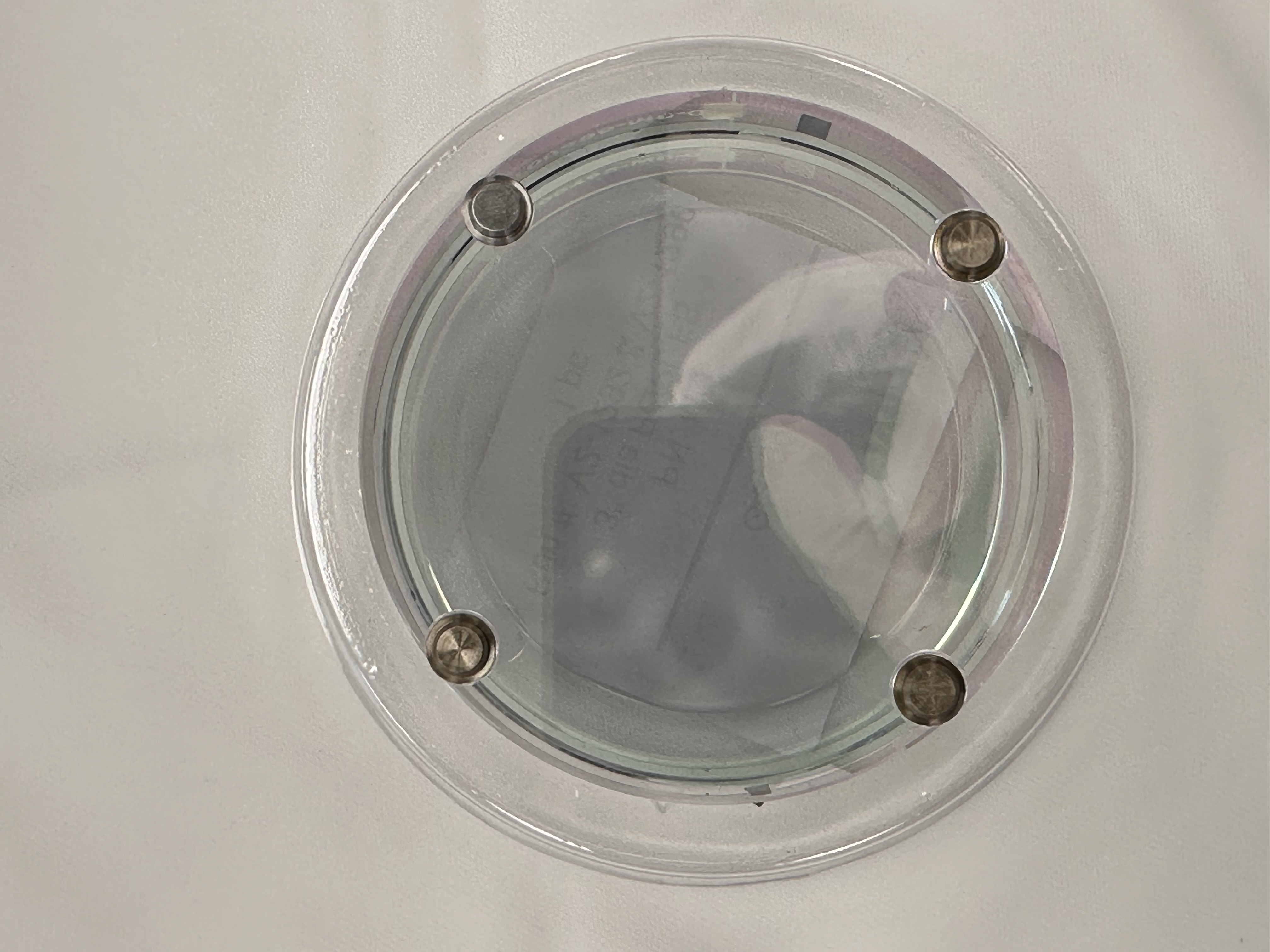
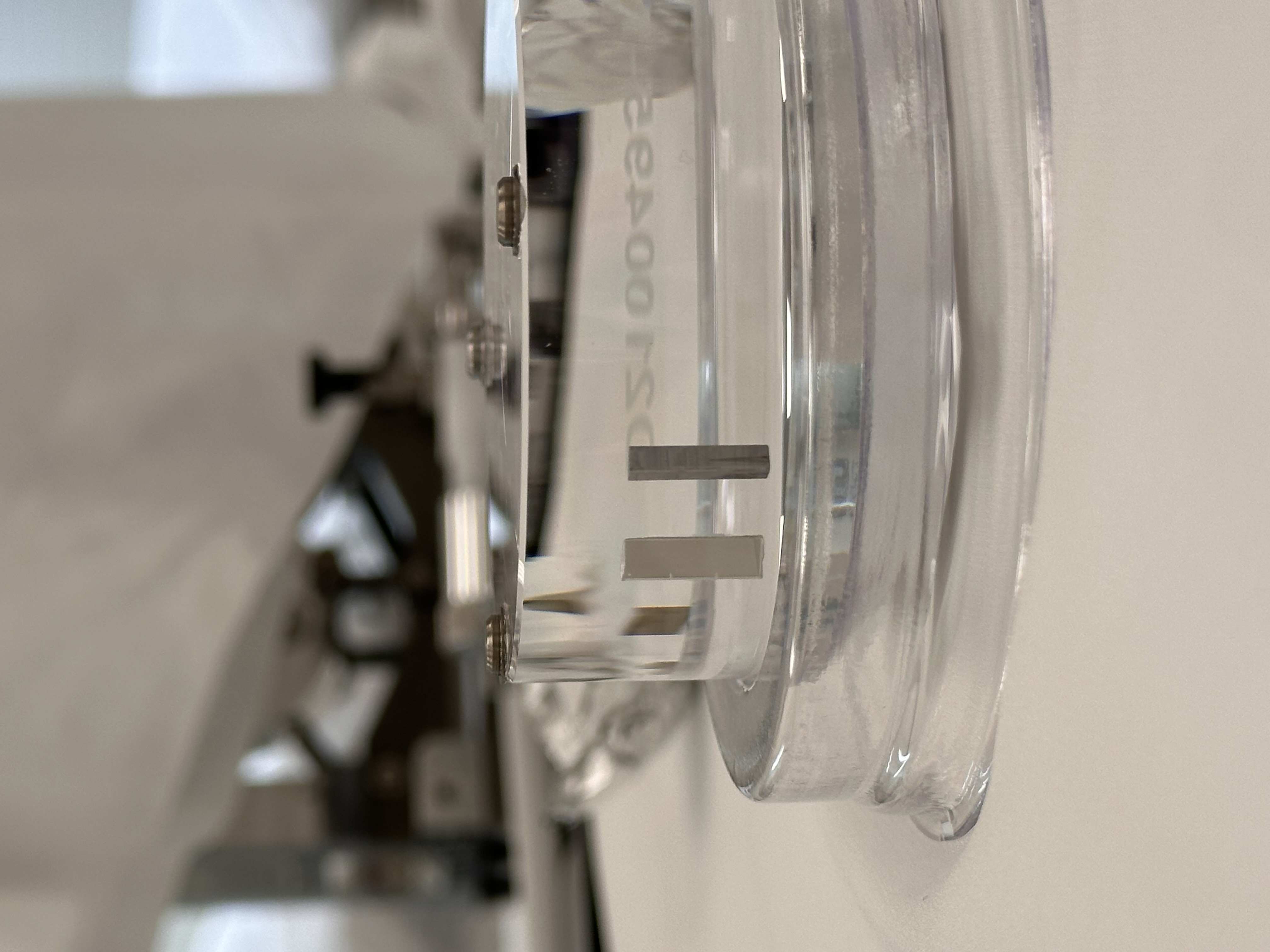
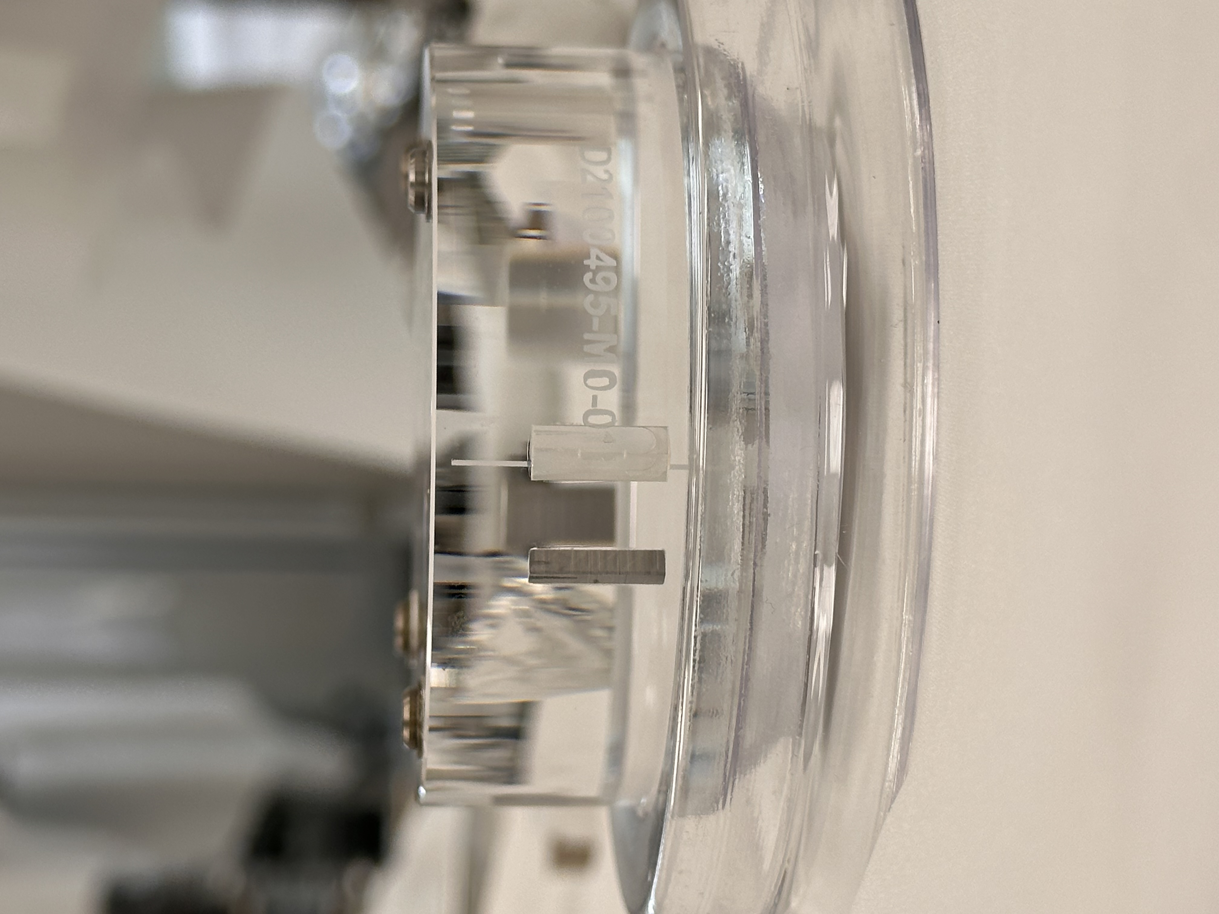
This week we glued prisms (primary - sapphire and secondary - metal) to the HRTS OM0 fused silica Optic (D2100495-V5-OM0-0001). The gluing measurement details are recorded in the DCC - google spreadsheet (T2600012), link given below,
https://caltech-my.sharepoint.com/:x:/g/personal/rmcrouch_caltech_edu/IQBWQ2S3pJX9TZYxfDaXsCvfAcJh-mrpHPS2JGNtku6Srcg
Attachment01 and attachment02 shows the prism-optic in the prism gluing jig.
Attachment03 and attachment04 shows the base for the Bosem magnet/flag glued to the AR side of the optic.
Attachment05 and attachment06 shows the two prisms glued on both the sides of the barrel of the optic. Notice that the arrow points to the HR surface and there is only one scribe line on the optic. While in the jig the arrow should be pointing down and on the right hand side of the gluing fixture (facing down).
The optic is now on its way to LLO and will be suspended in OM0 in HAM6 chamber.
Tagging for EPO.
Since nobody seems to have made an alog, here it is.
We've steered the JAC transmission beam into HAM2 and removed the viewport cover on HAM2 on the +Y side to look inside. At first we had a hard time seeing anything. We steered the beam in YAW and PIT and still nothing.
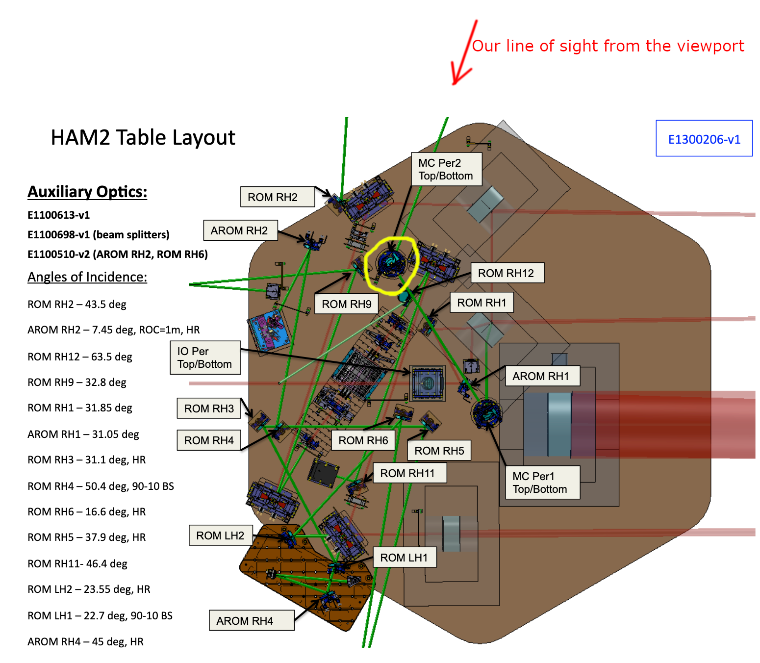
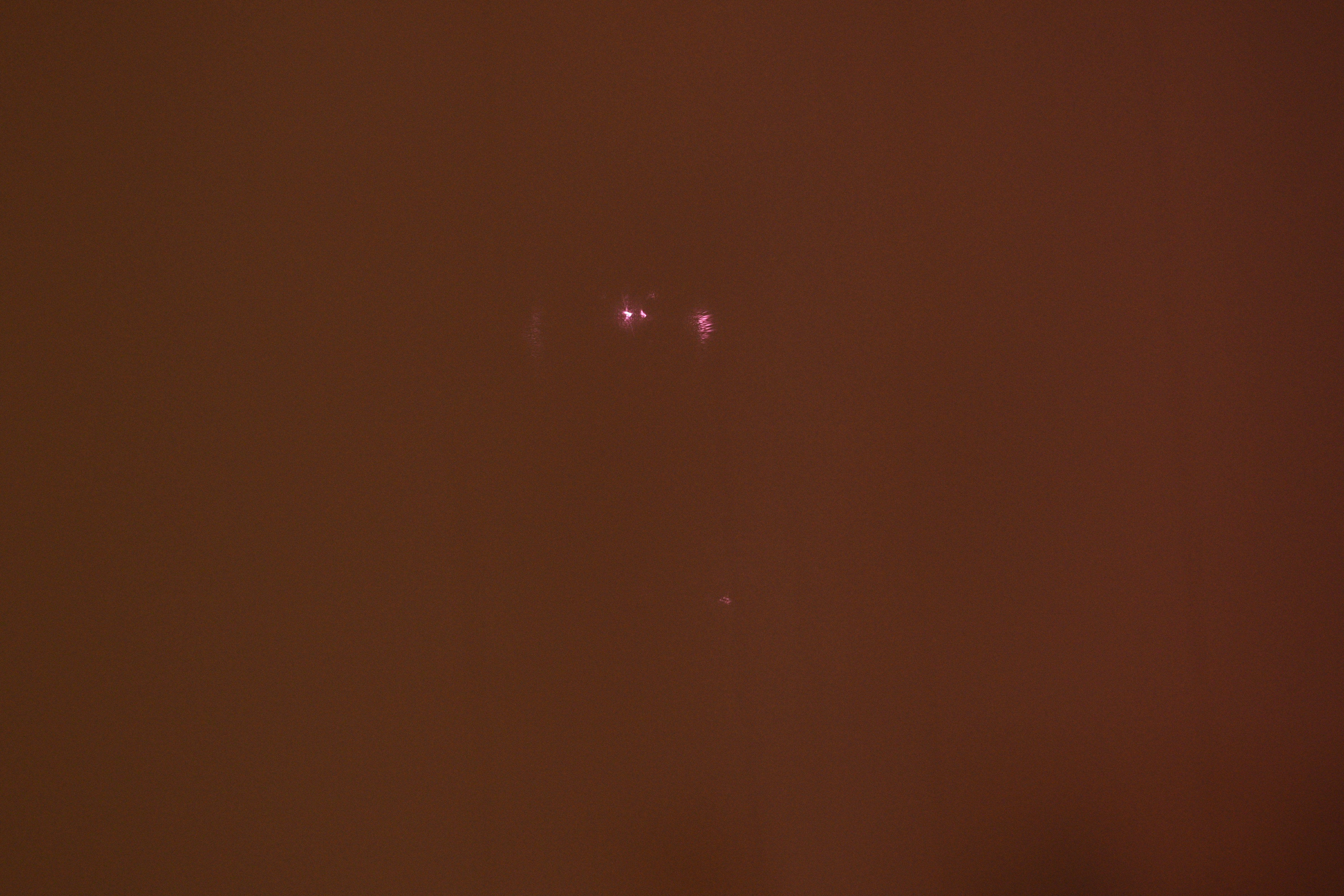
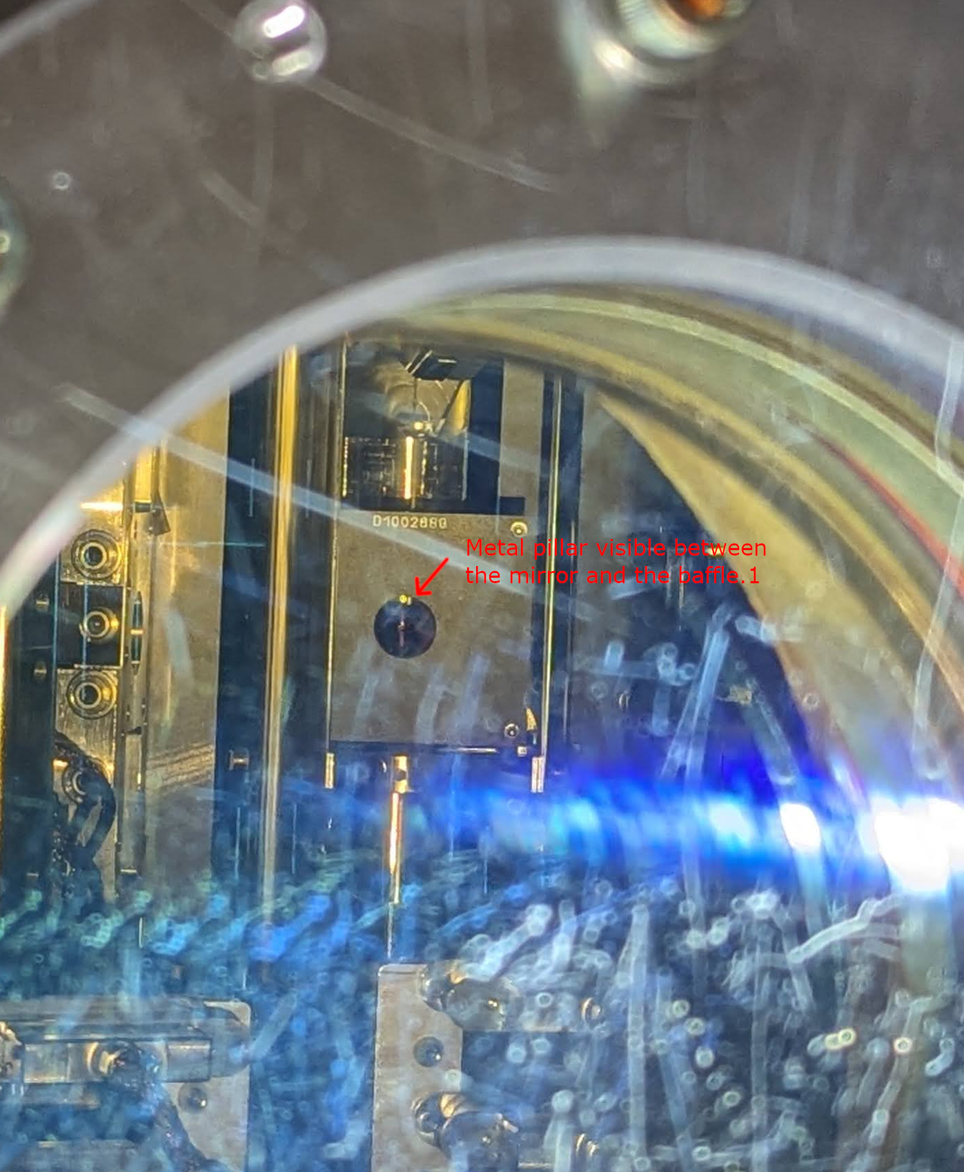
After a while we found that if we position the IR viewer at a specific position and look into the baffle hole of the MC refl periscope (circled in yellow in the 1st attachment), we can see some kind of ugly IR that definitely comes from JAC, but no beam seemed to be coming out of the baffle hole.
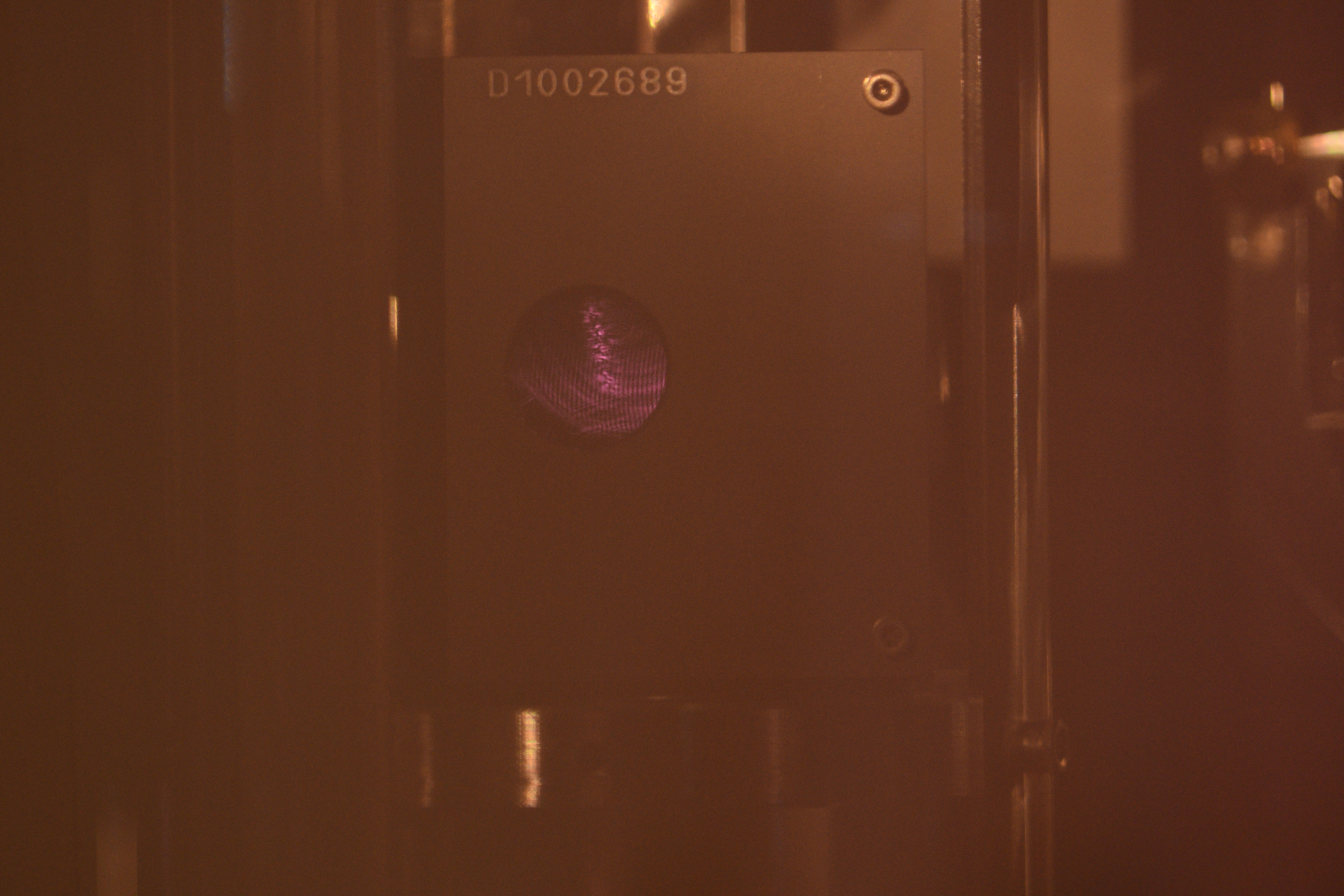
2nd attachment shows the picture shot by an IR sensitive camra when we focused on the IR, and the 3rd attachment shows the same picture shot from the same position but focused on the baffle.
The distance from the sensor to the subject according to the lens' indicator was something like 4m for IR and 1.5-2m for the baffle. The indicator is only good for visible light and not for IR, but empirically the scale is not a factor of 2 off for IR, so we're looking at something that is far from the baffle (i.e. we're looking at the image of the source reflected by the periscope mirrors).
Another possibility that Masayuki points out is that it could be some IR beam (probably not the main beam) hitting the vertical metal pillar of the periscope behind the bottom periscope mirror and we're looking at that through the space between the baffle hole and the periscope mirror (see the 4th attachment). I think that unlikely because the pillar is merely inches away from the baffle and the distance indicator of the lens doesn't agree. But we'll see.
Tomorrow we intend to remove the septum window cover for IFO REFL and POP and look into HAM2 from there, that way hopefully it's easier to find where the JAC beam lands in HAM2.
Tagging for EPO
Photos of trying to find the beam out of HAM2. I think the photographer was Jason and in the foreground is Keita, with Masayuki in the background.


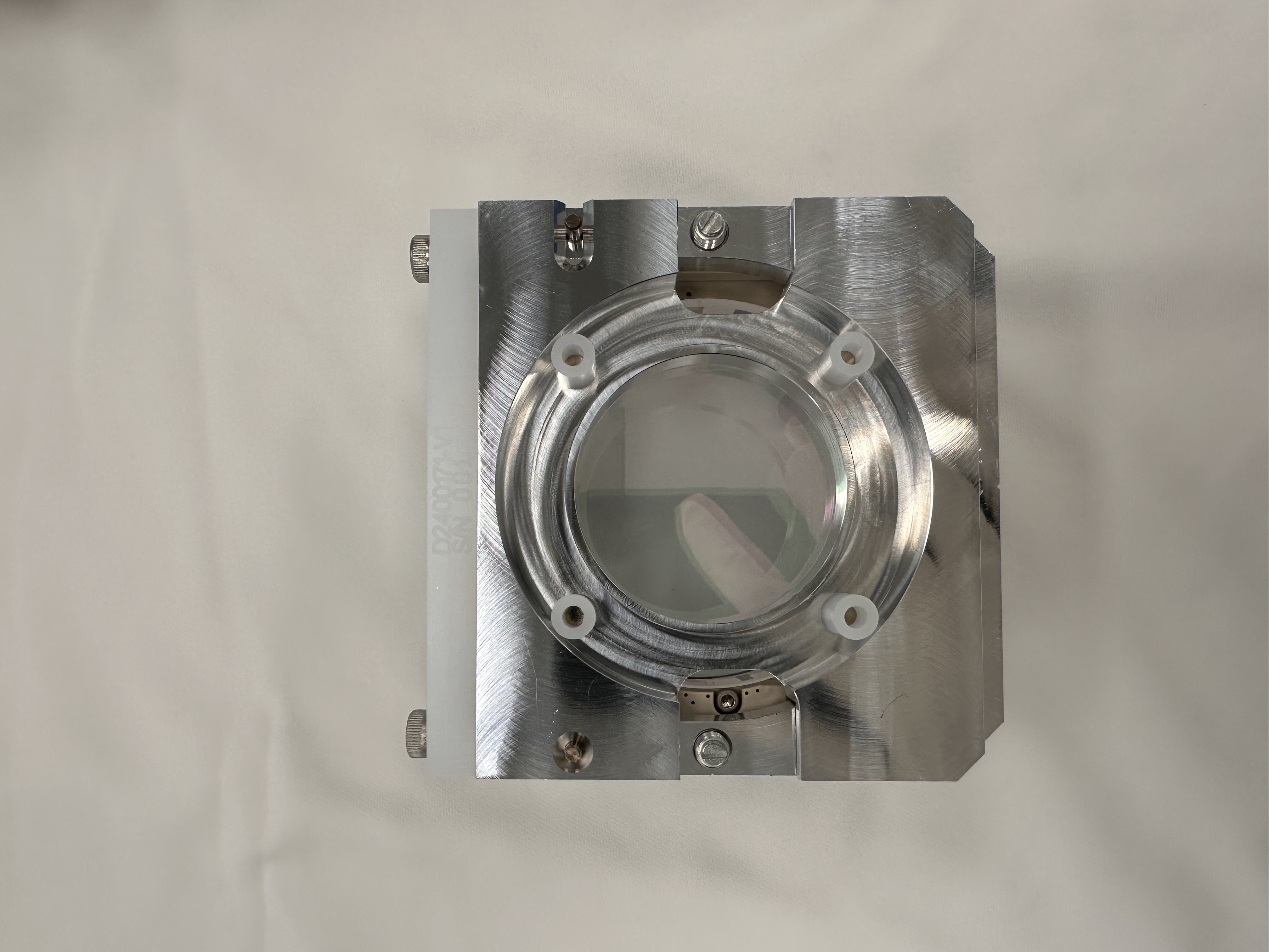
Attached is the mode-matching layout for the VOPO. The target primary waist of the VOPO (from TT1700104) is 221.2um(s), 206um(t) for 1064nm and 159.2um(s), 148.8um(t) for 532nm.
The mode matched minor and major beam waist is 198.6um, 204.2um for 1064nm and 152.6um, 185um for 532nm. For the fundamental injection via the rear mirror, the measured waist is 197.25um, 231.85um. These waist is measured at the position marked with a "star". The mode-matching calculation has been reviewed by a fur-low scientist.
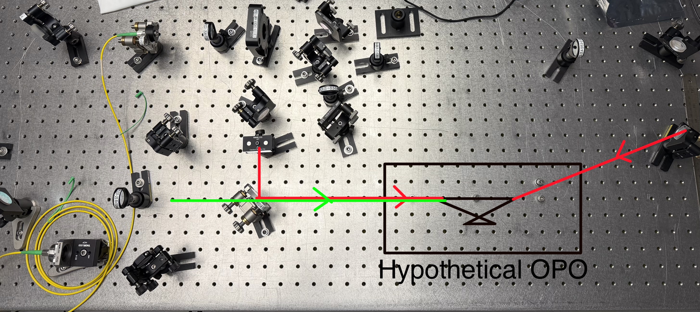
I have included a diagram showing the components remaining on the optical table, which can be used for testing the homodyne detector.
The attached file also includes the corresponding mode-matching calculation, indicating the resulting beam waist location along the remaining optical path, for future reference.
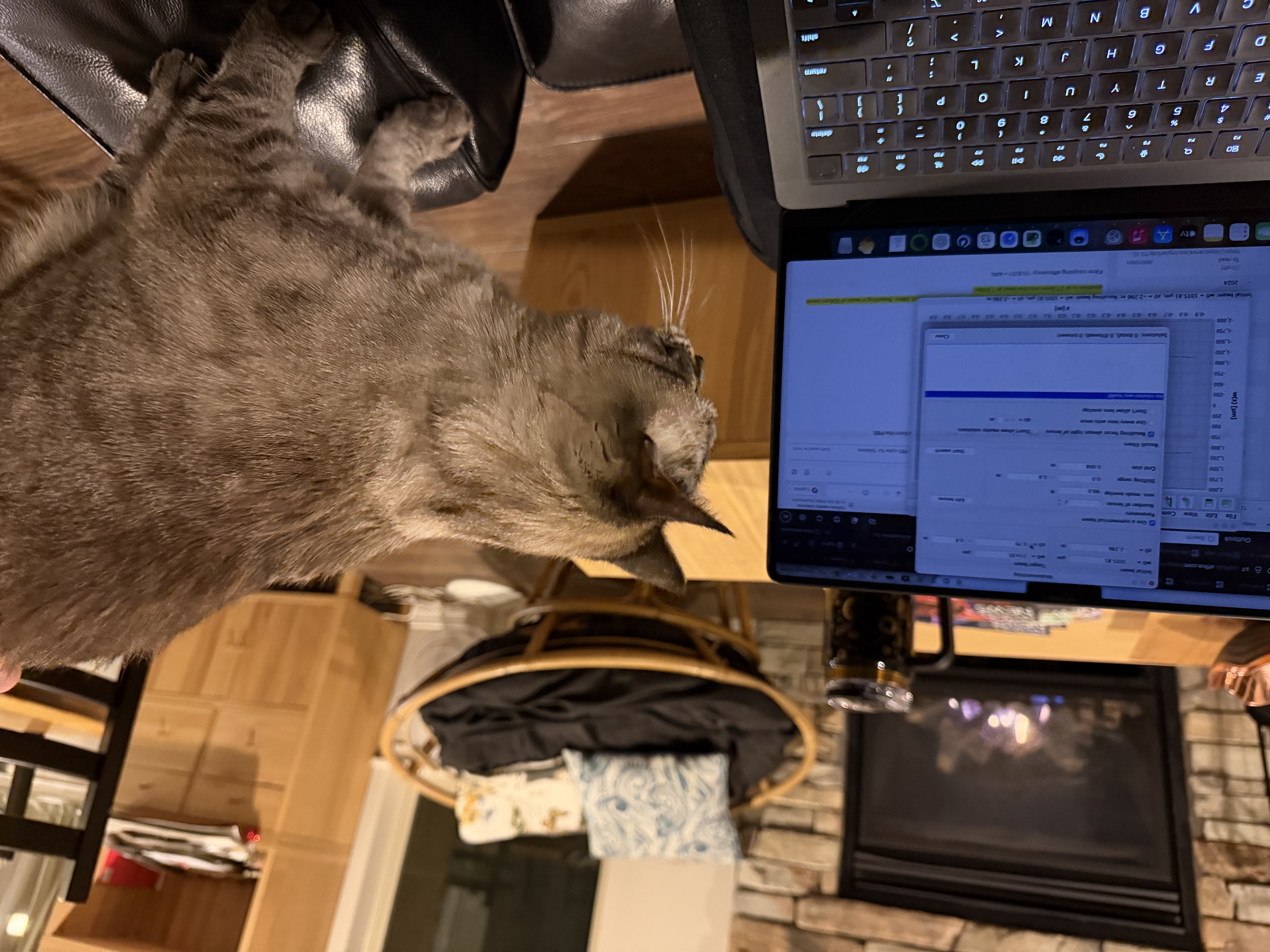
Tagging EPO for photo of fur-low scientist.

