TITLE: 01/26 Day Shift: 16:00-00:00 UTC (08:00-16:00 PST), all times posted in UTC
STATE of H1: Planned Engineering
INCOMING OPERATOR: None
SHIFT SUMMARY: SQZ laser was turned back on and LVEA moved back to Laser Hazard, work continued at HAM6, wind fence repair was started, HAM3 was cleaned in preparation for opening.
LOG:
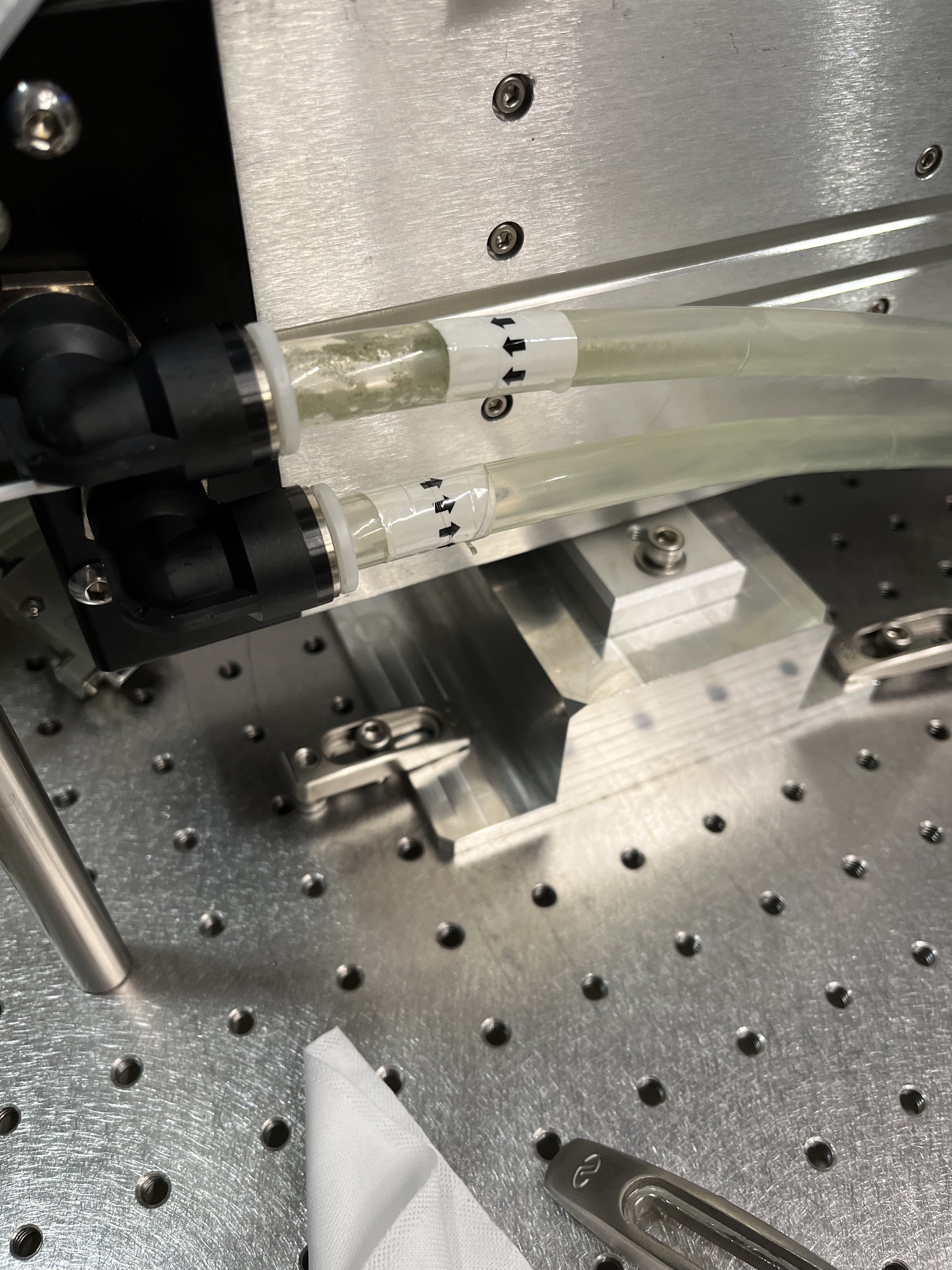
16:35UTC Team going into LVEA to check on the status of the TCS water leak
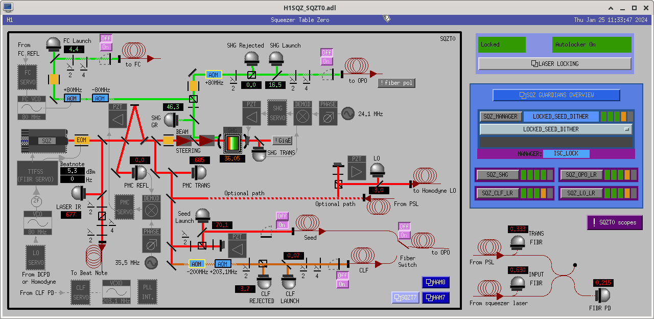
17:30 Squeezer laser okay to get turned back on; gets turned on
18:19 LVEA transition to LASER HAZARD
| Start Time | System | Name | Location | Lazer_Haz | Task | Time End |
|---|---|---|---|---|---|---|
| 18:19 | site | site | LVEA | YES | LVEA is LASER HAZARD !! | Ongoing |
| 22:17 | OMC | Betsy | LVEA | yes | See if HAM6 peeps need help | Ongoing |
| 15:30 | FAC | Randy | LVEA NB | n | Craning | 18:14 |
| 15:30 | FAC | Karen | OpticsLab,VacPrep | n | Tech clean | 16:07 |
| 16:07 | FAC | Kim,Karen | LVEA | n | Tech clean HAM 6/7 | 17:36 |
| 16:35 | SYS | TJ,Betsy,Fil | LVEA | NO | TCS Water Leak Recovery Check | 16:54 |
| 16:51 | FAC | Ken | MechRoom | n | Replacing lights | 00:22 |
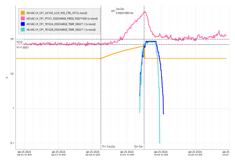
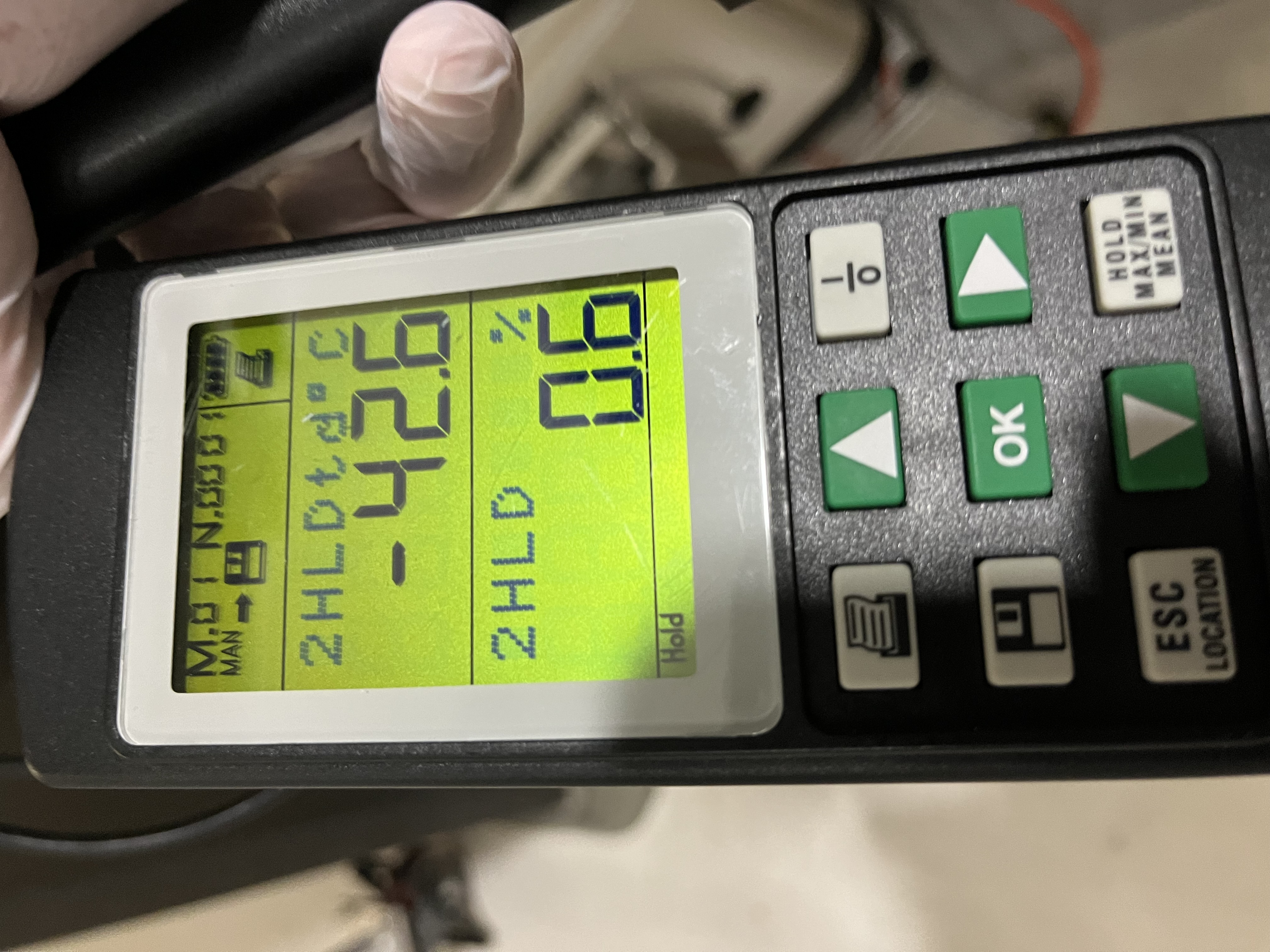
| 16:54 | VAC | Jordan | LVEA | n | Purge air measurement | 17:09 |
| 17:09 | VAC | Gerardo, Jordan | EX | n | RGA installation and swapping parts | 22:48 |
| 17:29 | EE | Fil,Camilla | LVEA | n | Turn on SQZ laser | 17:44 |
| 17:34 | FAC | Chris | LVEA | yes | Helping clean top of HAM3 | 18:43 |
| 17:36 | FAC | Kim,Karen | LVEA | yes | Tech clean HAM3 | 19:06 |
| 17:44 | FAC | Jim,Ryan S | LVEA | n | Helping move cleanroom | 17:58 |
| 17:50 | FAC | Eric | LVEA | n | Also helping move cleanroom | 18:07 |
| 18:10 | PEM | Robert | EX | n | Clean up for yesterday's work (didn't go yet) | 18:30 |
| 18:22 | SQZ | Camilla | LVEA | yes | Transitioning LVEA to laser hazard | 18:22 |
| 18:59 | FAC | Randy,Mitch,Jim | EY | n | Fixing wind fence | 23:16 |
| 19:07 | SUS | Ibrahim | LVEA | yes | Cleaning the outside of sus storage containers | 19:51 |
| 19:31 | OMC | Rahul, Koji | LVEA | yes | HAM6 work | 19:59 |
| 19:33 | PEM | Robert | EX | n | Clean up for yesterday's work | 23:33 |
| 19:34 | Camilla, Betsy | VacPrepLab | n | 19:51 | ||
| 19:35 | PCAL | Tony | PCal Lab | yes(local) | RespRat(responsivity ratio measurement) | 20:59 |
| 20:57 | EE | Fil | EY | n | Measuring cables | 23:52 |
| 21:01 | TCS | TJ | LVEA | yes | Looking for plumbing | 21:31 |
| 21:03 | Health | Camilla | MY | n | Getting healthier | 21:32 |
| 21:15 | SUS | Ibrahim | LVEA | yes | Cleaning the outside of storage containers pt2 | 22:05 |
| 21:41 | Tour | Sheila, Alan, interns | LVEA | yes | Tour of LVEA | 22:36 |
| 21:41 | CDS | Erik | EY | n | Replace failed power supply | 22:08 |
| 22:16 | Camilla | OpticsLab | n | Looking for stuff | 23:31 | |
| 22:23 | FAC | Tyler | EX | n | Meet with Jordan | 23:07 |
| 22:48 | VAC | Jordan, Janos | LVEA | yes | Looking for parts | 23:08 |
| 22:53 | Jason | LVEA | yes | Check Faro | 00:13 | |
| 23:45 | Ibrahim | LVEA | yes | HAM6 express delivery | 00:10 |
Fil, Jonathan, Erik, Dave:
At EY Fil found h1susauxey has its front panel FAIL LED lit. He tracked the issue down to a failed power supply. This is a redundant dual power supply system.
Strangely this system is not beeping, which is the default behaviour if a power supply unit is inserted but not operational.
The IPMI shell confirms that the system has correctly identified the failure:
ipmi sensor output:
OK | (2751) PS1 Status | Presence detected |
Fail | (2818) PS2 Status | Power Supply Failure detected |
TJ, Jason, Camilla, Fil.
WP11612, FRS25384, swapping because current CO2X laser was slowly deteriorating, details in 75249.
Removed: Access 50LT 20706.21015D. Installed 20306-20419D, which was refurbished/re-gassed in March 2020. Table layout: T1200007.
Still to do after the CO2X cooling line issue is solved:
FRS 30283 Created for this issue.
Tagging EPO for Thermal Compensation System (TCS) photos.
Thu Jan 25 10:02:32 2024 INFO: Fill completed in 2min 30secs
Robert, Mitchell, the vacuum team, the SLiC team
This morning we opened up 3 viewports and inserted dampers in between the baffle and the beamtube wall (Fig. 1). I was able to gently move the baffle, using the ”rails” of the eddy current dampers as position indicators in order to adjust the dampers to return the baffle to its original position. Before/after measurements did not deviate by more than 1/16 of an inch.
I used the laser vibrometer shining through a viewport to monitor the baffle. Figure 2 shows time series for beam tube impulses, indicating that the damping reduced the Q from about 400 to about 20 for the problematic 4 Hz peak. Thus, the cutoff frequency of the scattering shelf during high 4 Hz vibration levels should drop from the typical 50 Hz to about 2.5 Hz (so mostly just the 4Hz peak should remain and not harmonics). The second page of Fig. 2 shows before and after laser vibrometer spectra, which show that the main peaks did not move much, and adds evidence that the baffle is unlikely to be rubbing.
The viewports were closed this evening.
Today's activities: - 3 viewports have been taken off at EX for baffle works. These have been inspected, and found intact in every aspect - the inspection report is in the comment section - These viewports have been already taken back, as the works were already finished - The EX RGA is being rebuilt after many leaks have been found - it is in progress, will be finished tomorrow - The new Hepta header elbow pieces have been staged at all stations
Following the installation of the new OMC yesterday ( alog 75529), we started aligning the laser into the OMC.
Preparation:
Vicky enabled the WFS centering to center the SQZ beam (LOCKED_SEED_DITHER state) reflected by the SRM on AS_A and AS_B. At this point almost nothing was visible on the OMC QPDs.
We increased the whitening gain of the OMC QPDs (H1:ASC-OMC_A_WHITEN_GAIN and H1:ASC-OMC_B_WHITEN_GAIN) to 45dB from the original 0dB and reset the dark offset.
Initial beam search. Beam visible on OMC QPDs only when OM3 is totally railed in PIT no matter what:
We started scanning OM3, and saw nice beam at the edge of both of the QPDs but only when OM3 was completely railing in PIT.
We disabled the WFS centering and started using OM2 and OM1 to make the beam more centered on the OMC QPDs. I was able to make it somewhat better but not really, and more importantly, no matter what I did, I could not releave OM3 PIT offset at all. Whenever I removed a bit of OM3 PIT and tried to use the combination of OM1 and OM2, I was only able to make it worse.
I also used OMCS offsets, but it made no meaningful impact as the alignment was so bad and the OMCS range so small.
Diagnosis and mitigation part 1, things are making sense:
These all indicated that the OMC has a big PIT tilt relative to the old OMC. This was corroborated by our observation yesterday that one corner of the OMC breadboard was hitting the EQ stop structure and we couldn't release the OMC without moving the EQ stop bracket itself down. According to alog 75529, "We noticed a corner of the OMC on the HAM5 side was bottoming on an EQ stop. We decided to lower the EQ stop by releasing the fixing screws for the EQ stop holder. The holder was tilted, and the OMC became free."
With this knowledge, we went back to HAM6 to rebalance the OMC suspension in PIT.
Rahul and Koji pushed the PITCH Insert mass (part number 14 in https://dcc.ligo.org/D060502) by about 5mm into the direction of HAM7. We immediately lost the beam on the OMC QPDs, but relieving the PIT offset by 1000 counts (out of the total of 3500 counts), we regained the beam, so the adjustment was in the right direction.
The intermediate conclusion is that OMC breadboard is tilted in PIT such that the long edge at -X side was too low. We at least partially relieved it by tilting the intermediate mass to counter that.
I thought that another step or two would be great, but at that point we had to stop our work. We'll continue tomorrow.
Picture 1: Rahul, Dana and Koji from left to right.
Picture 2: Tired scientists.
Anatomy of the "T-section" Pitch Balancer on OMCS
The attached snap shot taken from D060502 explains how the pitch balancer works.
Tagging for EPO photos.
TITLE: 01/24 Day Shift: 16:00-00:00 UTC (08:00-16:00 PST), all times posted in UTC
STATE of H1: Planned Engineering
INCOMING OPERATOR: None
SHIFT SUMMARY:
LOG:
For the record, late alog - a couple weeks ago the EY wind fence was found to be damaged, again from early JAN severe winds (50+mph gusts for a few days).
Plans are in place to repair it with an improved round of reinforcement. A second snorkel lift is being delivered to aid in the repair scheduled for ~next week. FRS ticket filed.
tagging EPO for our EY wind fence
Naoki Vicky Daniel
We physically placed the PMC, the RF photodetector, and a bunch of steering mirrors into the empty space on SQZT0. Everything seems to fit as planned. No beams yet!
We also installed the Thorlabs PDA100A that serves as the PMC_TRANS monitor. It is installed along the seed path. There is a 50:50 splitter that reduces the seed power by 2. We installed a one-side AR coated wedge in the path of the beam dump to get about 19mW of light that we steered onto the PDA100A.
The slow controls system was upgraded to add new channels associated with the PMC and update some channels names. There is no longer a FIBR_REJECTED PD, instead we added a FIBR_INPUT PD that monitors the fiber power from squeezer laser in the beat note box.We no longer have a monitor for light in the wrong polarization at the laser locking beat note. Instead, we have to use the beat note strength to optmize the input polarization.
Some photos here. Here is the PMC TRANS PD path and aligment, including the beam dumps. Here's a photo of PMC + RFPD fitting into the table, to-be aligned afterwards. The SHG beam path clears the back of the PMC, so that's good.
We also installed a longpass filter onto the SEED_LAUNCH_PD (FEL0850, cuts-on above 850nm), so we can now open the SQZT0 table lights without changing the measured seed launch power.
Updated medm
[Rahul Betsy Keita Ali Koji]
The extraction of the old OMC (Unit #3) and installation of the new OMC (Unit #1) went exceptionally well.
= OMC Extraction =
Tuesday morning, we resumed HAM6 work from the OMC extraction.
Rahul and Koji went into the chamber. Rahul positioned close to HAM5, and Koji was on the other side.
They followed the extraction procedure (E1600164) after some rehearsals.
During the OMC extraction, assistance from two others was very effective in supporting wires from both HAM6 openings, preventing the wires from touching the OMC. (The procedure to be updated)
The extracted OMC was placed in the fixture on the ISI and moved back to the work table for further action.
= Balance Mass Migration =
Balancing masses were transferred from the previous OMC to the new one (Attachment 1). At the same time, a Viton ring and a 10g mass were added to each corner for the body mode damping (See T1700471).
The mass distribution differed from what Koji had figured out from the past unclear photos. But the masses could be fixed to the OMC using various 1/4-20 screws that were prepared for this.
Only light torque was applied to the fixing screws to avoid delamination/fracture of the mounting brackets below the mass mount.
= Final OMC cleaning =
All the optical surfaces were cleaned by FirstContact except for a couple of surfaces where the access was quite limited. (Attachment 2)
We let the FC paint dry during lunch and then resumed peeling them off, combined with discharging with Top Gun.
The surfaces were checked with a flashlight to find any residual.
A FC residual was located not on the optical surface but on the corner of a tombstone prism. It was cleaned with additional FC paint.
In parallel with the cleaning work, Ali and Keita worked on the review of DCPD-related cable shielding in HAM6.
= OMC Installation =
The reverse process of the extraction has been performed.
When inserting the clamps into the clamp hooks, sometimes incomplete mating happens due to friction between the copper cone and the frosted glass cup.
This can be fixed by pushing the clamp into the slit by a small flat-head driver, while the tension on the wire was released by lifting that side of the OMC.
= EQ stop release =
Reverse process of the OMCS mass clamping.
This made the OMC free. Rahul quickly checked the transfer functions of the OMCS as well as the damping control.
We decided to stop here. (Attachment 3)
Next Steps:
The attached PDF shows the previous and current balance mass configurations.
The highest mass has the height of 2 7/8" from the mating plane of the fixture, while the fixture has 3" clearance,
So we still could close the lid with the gap of 1/8".
Wonderful, CONGRATS!!!
Koji, Keita, and Rahul in HAM6.
Tagging EPO for photos
[Julian, Naoki, Camilla, Sheila, Vicky]
Summary to get SQZ alignment beam: Launched 76mW into seed fiber, ~25 mW incident on opo cavity, ~0.85 mW transmitted through opo cavity. Had to find opo transmission past the VIP, for this we used green SK path as a reference. This ~0.85 mW opo transmission was bright on an IR card at the HAM5 gate valve, and enough to iris the SQZ beam in HAM7 and HAM6 (for OMC work 75512). DC 3/4 centering loops engaged easily, then OMC A/B QPD's saw the sqz beam.
----------- Notes from today ------------------------------------------
Launched power into SEED fiber (SQZT0): 76 mW
OPO IR REFL (CLF_TRIG_REFL_DC_POWERMON @ SQZT7): 24.8mW (when opo is dither-locked).
Fiber rejected power PD in HAM7 (CLF_REFL_REJ) is 5.3 mW.
--> Seed fiber coupling: ~34% of the seed fiber launched power was incident on the opo cavity.
--> 40% coupling through fiber, ~6% mispolarized and rejected after fiber. This is similar to recent fiber alignment 75344, even after more recent on-table work 75486.
We had to find the OPO IR transmitted beam after the VIP. Nothing at first despite restoring suspensions 75502. Notes to self on what worked to find the SQZ beam post-vent:
OPO IR TRANS (OPO_IR_PD_DC_POWERMON @ SQZT7): 0.85 mW -- Just before opening the HAM7/5 gate valves. Opened the beam diverter, SQZ beam was bright on an IR card held at the HAM5 gate valve.
After opening gate valve, immediately saw the beam on AS A/B/C QPDs.
ASC-AS_A/B_DC_SUM_OUTPUT ~ 60. ASC-AS_C_NSUM_OUT16 ~ 0.65-0.67.
HAM6 crew irising SQZ beam, 75512.
HAM7 crew irising SQZ beam. Julian has some photos of HAM6 and HAM7 irses. Sheila -- looks like there is some clipping on the VIP (we have not totally optimized FC_REFL path slider alignments post-vent, just found the beam). Revisit this FC REFL alignment later.
Engaged DC 3/4 centering. It just worked. Control signals near 0.
We see the beam on the OMC QPD's, power is consistent with ASC-AS_C power, around 300-400e-6 on each OMC QPD A/B. Power goes away when SQZ beam diverter is closed. See omc powers screenshot with as_wfs powers.
TO-DO SQZ work later:
tagging for EPO
Accepted ZM1,2,3,4,5,6, FC1,2 OPTICALIGN sliders in sdf. Attached is the photo so we'll know where to bring them back to after pumpdown.
ZM4,5,6 are not monitored - should remember why that is....
Camilla, Naoki, Vicky
Next day 1/23, we tried to help check OMC alignment, but after turning the SQZ laser back on, we didn't find the beam past the VIP at first.
To re-find the sqz beam, we had to move FC1 quite a bit (pitch slider by 100 counts, yaw slider by 65 counts). See FC1 SDF's of today's move, compared to what Camilla just accepted in SDF after we first found the beam yesterday 75517.
Naoki checked FC1 and ZM1-2-3-4-5-6 SUS, and did not see any anomolous movements of the optics.
We left FC1 with an alignment that maximizes signal on both HAM7 FC WFS (RLF QPD's). Both QPD's are now saturated with 75mW into the fiber. With 5mW into the fiber to un-saturate, both QPD's are close-ish to centered.
Hopefully this is enough to use AS A/B WFS centering tomorrow. Today when we tried it, DC3 worked, but DC4 railed as the beam wasn't hitting AS_B well.
Sheila, Camilla, Vicky
We re-found the SQZ beam in HAM6 this morning after opening the ham5 gate valve. Steps taken this morning 1/24, after yesterday using FC1 to align onto the HAM7 FC WFS QPD's:
For convenience while vented, I made the following guardian changes so far:
All guardian edits (+sqz angle servo flag in sqzparams.py) commited to svn revision 27088.
Attached Julian's photos of the iris locations on HAM6 and HAM7.
[Rahul, Keita, Betsy, Koji]
Preparation work to extract the existing OMC has been completed. We will continue with the OMC extraction tomorrow morning.
The overall work procedure for the OMC replacement is summarized in G231106 https://dcc.ligo.org/LIGO-G231106.
= OMC shroud panel removal =
While waiting for the beam from the squeezer to come, we started the removal of the OMC shroud panel in parallel. The work was done along with the procedure E1600164.
The removed panels were placed on a stainless steel table in the HEPA booth of HAM6 (Attachment 1). The panels were not covered to prevent accidental placement of objects on them.
During the work, a beam dump was removed from the table to make the removal work possible. This beam dump is to kill one of the weak transmissions of the OMC.
Betsy took the photo record of the location, but it is safely trivial how it should be aligned.
= SQZ beam marking and alignment =
The beam was delivered to HAM6 and was pinned down with two irises on the ISI table.
The irises were placed just after the beam entered HAM6 (next to OM2) and just before OM1 (next to the fast shutter).
This means that these indicators are not affected by the alignment in HAM6.
They were placed by eyeballing, so their precision was as such. By default, both the irises were set to the maximum opening.
Next, the beam alignment was servoed towards the WFS heads using the DC centering ASC loops.
As soon as the control was applied, both QPDA and QPDB of OMC showed significant signals with total light level of ~1e-3 (Attachment 2).
When the light was blocked (at the squeezer?), the value dropped to almost zero, confirming that this was a real beam.
This is very good news as we'll be able to find the beam arrival using the OMC QPDs when we try to align the new OMC.
= Holding suspension mass =
Next, we proceeded to hold the suspension masses. Rahul and Koji worked in the chamber on the ISI table for the following operations.
To hold the intermediate mass:
Then, moved onto fixing the OMC:
= Removing the electronic cables from the OMC =
Upon removing the electronics cables, one person held the cable harness on the OMC breadboard to prevent the OMC from wobbling too much.
The removed cables were wrapped around the top part of the suspension frame to keep them out of the way of the further work.
At this point, it was just at 5pm, so we exited from the chamber.
Next Steps:
WP11652
Erik replaced the failed power supply with a good spare, status is good
h1susauxey: OK | (2751) PS1 Status | Presence detected |
h1susauxey: OK | (2818) PS2 Status | Presence detected |