david.barker@LIGO.ORG - posted 10:15, Tuesday 20 January 2026 (88800)
Tue CP1 Fill
Tue Jan 20 10:09:37 2026 INFO: Fill completed in 9min 33secs
Images attached to this report
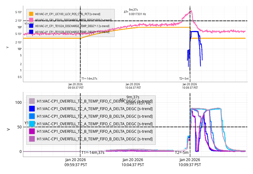
Tue Jan 20 10:09:37 2026 INFO: Fill completed in 9min 33secs
FAMIS 27832 TCS Chiller Water Level Top-Off - BiWeekly.
| TCS X | TCS Y | |
|---|---|---|
| Previous Level | 29.9 | 9.9 |
| New Level | 30.5 | 175 |
| Water added mL | 250 | 10.4 |
Values added to spreadsheet.
Workstations were updated and rebooted. This was an OS packages update. Conda packages were not updated.
TITLE: 01/20 Day Shift: 1530-0030 UTC (0730-1630 PST), all times posted in UTC
STATE of H1: Planned Engineering
OUTGOING OPERATOR: None
CURRENT ENVIRONMENT:
SEI_ENV state: MAINTENANCE
Wind: 9mph Gusts, 5mph 3min avg
Primary useism: 0.02 μm/s
Secondary useism: 0.25 μm/s
QUICK SUMMARY:
Tuesday Maintenance Day today, but also we will be wanting to go back to Laser Hazard for the morning to finish up the HAM7 alignment, before doing some back and forth to and from laser safe.
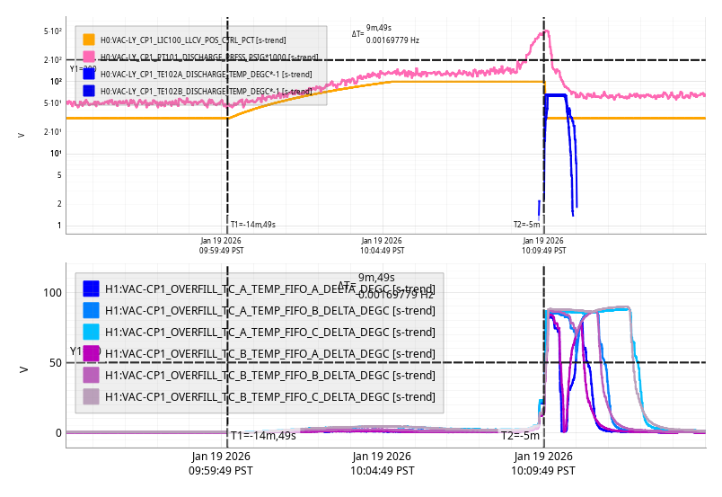
Mon Jan 19 10:09:49 2026 INFO: Fill completed in 9min 46secs
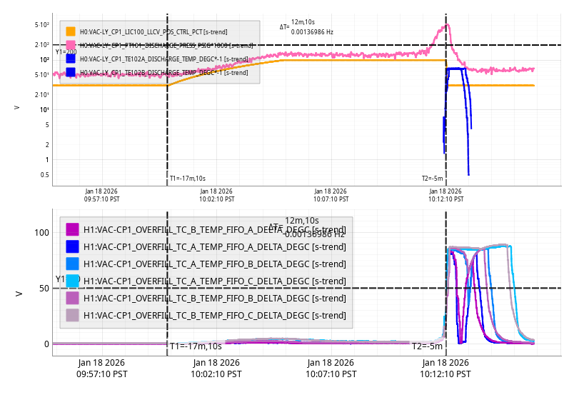
Sun Jan 18 10:12:10 2026 INFO: Fill completed in 12min 6secs
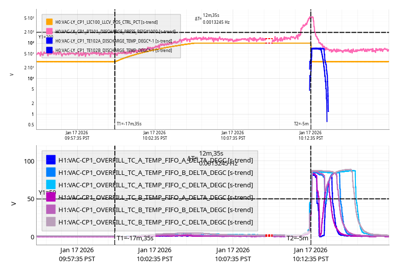
Sat Jan 17 10:12:35 2026 INFO: Fill completed in 12min 31secs
TITLE: 01/16 Day Shift: 1530-0030 UTC (0730-1630 PST), all times posted in UTC
STATE of H1: Planned Engineering
INCOMING OPERATOR: None
SHIFT SUMMARY: Lots of work got done today. We are leaving the LVEA in LASER SAFE over the weekend
LOG:
To do items for today:
DONE Finish alignment out IOT2L viewport
DONE Move ZM4 to realign onto ZM5
DONE Lift BSC2 platform and remove PEM gold plate
DONE Roll up IOT2L to HAM2
DONE Cable up IOT2L
DONE Install bellows between HAM2 and IOT2L
| Start Time | System | Name | Location | Lazer_Haz | Task | Time End |
|---|---|---|---|---|---|---|
| 17:16 | SAF | HAZARD | LVEA | n | LVEA is Laser HAZARD | 21:19 |
| 15:46 | FAC | Randy | LVEA | YES | Removing braces from BSC2 | 16:43 |
| 15:54 | FAC | Kim, Nellie | LVEA | YES | Tech clean | 17:03 |
| 16:15 | JAC | Masayuki | LVEA | YES | JAC alignment | 19:54 |
| 16:47 | Corey | LVEA | YES | Looking for bellows | 16:17 | |
| 17:02 | JAC | Jason | LVEA | YES | JAC alignment | 19:54 |
| 17:16 | JAC | Jennie | LVEA | YES | JAC alignment | 19:55 |
| 17:23 | SQZ | KarMeng | LVEA | YES | HAM7 work | 17:32 |
| 17:53 | JAC | Keita | LVEA | YES | JAC alignment | 19:06 |
| 18:37 | CDS | Jeff | LVEA | YES | Moving cables around | 19:16 |
| 18:43 | SQZ | Sheila, Rahul, KarMeng | LVEA | YES | SQZ alignment (Rahul out 20:02) | 21:03 |
| 20:48 | FAC | Randy | LVEA | n | Moving IOT2L | 22:18 |
| 20:49 | FAC | Marc, Corey | LVEA | n | Moving IOT2L (Corey out 22:08) | 22:32 |
| 20:50 | LASER | RyanC | LVEA | Y | Transitioning to LASER SAFE | 21:12 |
| 21:14 | CHETA | Matt, Sophie | JOAT Lab | n | Poking optics | 21:42 |
| 21:18 | SEI | Jim | LVEA | n | Locking BSC2 HEPI | 22:04 |
| 21:23 | FAC | Richard | LVEA | n | Ruining weekends | 21:30 |
| 22:35 | FAC | Tyler | LVEA | n | 23:05 | |
| 22:50 | ISC | Corey | LVEA | n | Installing IOT2L bellows | 23:43 |
| 22:58 | PEM | Robert | LVEA | n | BSC2 investigation | 00:58 |
| 23:23 | SQZ | Sheila, Robert | LVEA | n | Grabbing a cable | 00:08 |
| 23:27 | CHETA | Jennie | JOAT Lab | n | Putting parts away | 23:33 |
| 00:02 | Tyler, tour | LVEA | n | Tour | 01:02 | |
| 00:02 | FIT | Masayuki | YARM | n | Running | 00:30 |
[Jennie, Jason, Rahul, Keita, Masayuki]
We have observed the light coming out from the HAM2 after the MC1 reflection.
This is the summary report for the optics alignment in HAM1 after the JAC.
An iris was placed and centered on the output beam from the JAC before installing the L1 lens. The lens was then installed such that the beam remained centered on the iris.
JM2
This optic will need to be repositioned after the EOM is installed. Therefore, we placed it without fine adjustment for now. The angular alignment was done using an iris located at the position where the HR surface of JM3 will be. Notes for final installation:
The barrel must be cleaned before final installation.
A beam dump must be installed behind the mirror.
JM3
Although JM3 also needs to be swapped to tip-tilt, the beam reflected from JM3 serves as the alignment reference after the EOM. Therefore, we performed careful alignment. An iris was placed at the planned location of JAC_M3, and the beam was centered on it by adjusting JM3.
JAC_L2, JAC_L3
The two lenses were then installed. They were centered using the same iris that had been used for the JM3 alignment.
JAC_M3
The angle of the reflected beam from JAC_M3 is critical, as it determines the polarization mismatch caused by the periscope’s rotation. An iris was placed at the output beam hole, and the beam was aligned parallel to the hole line. Previous measurements confirm that the input beam axis to the IMC in HAM1 is parallel to the hole within ~1 mrad ([link]). Therefore, this alignment ensures that the polarization mismatch remains within acceptable limits.
Periscope (initial alignment attempts)
Initial alignment of the periscope was performed using the first iris (IR1) placed prior to installation.
Since the incoming beam was horizontal and parallel to the hole line, we expected the output beam to be rotated by exactly 90° and remain horizontal through the hole. After centering the beam on the iris by eye, we checked from the HAM2 viewport but did not observe the beam.
We attempted minor adjustments to the periscope, JM2, and JAC_M3. Some scattered light was eventually seen at the output periscope of the HAM2 IMC reflection path. However, IR camera footage from Keita showed that the focus did not match, and the light was deemed irrelevant. The detail can be found in Keita's alog.
Periscope (refined alignment)
On the following day, a second iris (IR2) was introduced to further constrain the horizontal alignment. This iris was placed approximately at the same height as IR1 and roughly aligned parallel to the hole line. The periscope was then re-aligned to pass through both irises.
From the POP septum window, we confirmed that the HAM2 periscope was visible and used it for alignment. Using an IR viewer, the beam was observed to hit the upper-left (10 o’clock) corner of the periscope structure. We switched to aligning JM2 and JAC_M3 using the top periscope mirror and IR1 as references (IR2 was removed at this point).
To identify the beam spot, we intentionally misaligned the pitch to make the beam hit the upper part of the periscope structure. To avoid blocking the beam, the iris was temporarily removed (its location was marked with three dog clamps; one clamp was slightly loose but the offset was minor, ~1 mm).
While keeping the pitch misaligned, yaw centering was performed using JAC_M3. Once centered visually, the iris was replaced, and JM2 was used to center the beam through it.
Fortunately, JM2 and the periscope top mirror are located at similar opical position, so the beam position remained nearly unchanged on the periscope mirror. This beam walking converged in two iterations.
The iris was removed again, and the beam was swept from top to bottom of the top periscope mirror using JAC_M3. The mirror was then centered using the midpoint of this motion. The iris was replaced, and pitch alignment was re-checked using JM2, again requiring just two iterations.
At this stage, some faint beam was observed using the viewer through the viewport. Although it wasn’t visible on a card, adjusting JAC_M3 slightly allowed us to confirm beam output from HAM2.
Final Checks
Finally, the IR1 centering was confirmed, and IR2 was placed near the periscope to act as a reference.
When checking the beam on JAC_L3, we found that it was offset by about 5 mm in the yaw direction. Further alignment is likely needed.
The beam spot on the periscope mirror is not perfectly centered, but it is close enough that no adjustment to the top mirror is deemed necessary.
tagging for nice JAC team photo for EPO.
Pictures for posterity.


Locked BSC2 HEPI this afternoon so Randy and I could try to get the PEM accel plates of the south end of the support tubes. Plan was to try to crane the south end of the work platform, but the platform didn't like being picked up from just one end and it looked like it was going to swing into the crossbeam. We set the platform back down and just pulled all of the screws out of the PEM plates. Turned out there was just enough room to get the blocked screws out, if you used pliers or fingers to back them out. Plates are off, platform is moved back into position, I think Randy was going to put the braces back on.
[Sheila, Rahul, Karmeng]
A continuation of yesterday's progress. The additional power observed yesterday was due to the green for FC lock. We measured 0.75mW exiting the OPO, 0.74mW after SFI1 and also on the SQZT7 homodyne detector.
Today we reduced the saturation on ZM4 by clearing the offset and physically rotate the ZM4, we recovered the alignment on OMC QPDs and SQZT7 irises.
We also aligned the beam back to the HAM7 QPD A and B, at ~100nW for both of them, will need to re-centre the beam once we're back to laser hazard.
Friday, we recentered the beam onto the OPO pump fiber rejected PD.
Robert and I also went to the chamber in laser safe in the afternoon and reattached the cable clamp to the pillar on the hard to reach side of the VIP, and took phots of the camble routhing and iris locations.
Since we adjusted the alignment of B:M4 while moving the beam location in SFI2, we had to realing the path to the FC QPDs as Kar Meng mentioned above. We did this using the seed beam because that beam can be seen on a card, but it saturated the QPDs. We walked the pointing until the beam was on both QPDs as seen by saturating all the quadrants, we will want to use the CLF beam to actually center on these QPDs so that we aren't saturating.
Still to do in HAM7 in laser hazard:
Not in laser hazard:
Sheila, Karmeng, Rahul
This morning we physically moved ZM4 (since the sliders were saturating the DAQ output) in YAW to better align it with ZM5 and ZM6. More details (including health check results) will be posted later.
ZM4 is now dogged down to its new position.
I ran a quick transfer functions on ZM4, a few things to note. The suspension is in air so I changed the Coil Driver state from 2 to 1 (reverted once I was done) as the wiki suggested, the ISI is also tripped but the damping was engaged on the suspension. We were also slightly shaking due to an 6.1 earthquake from near Japan.
The suspension is looking healthy.
/ligo/svncommon/SusSVN/sus/trunk/HXDS/H1/ZM4/SAGM1/Data/
2026-01-21_1700_H1SUSZM4_M1_WhiteNoise_L_0p01to50Hz.xml
2026-01-21_1700_H1SUSZM4_M1_WhiteNoise_P_0p01to50Hz.xml
2026-01-21_1700_H1SUSZM4_M1_WhiteNoise_Y_0p01to50Hz.xml


Betsy, RyanC, Rahul
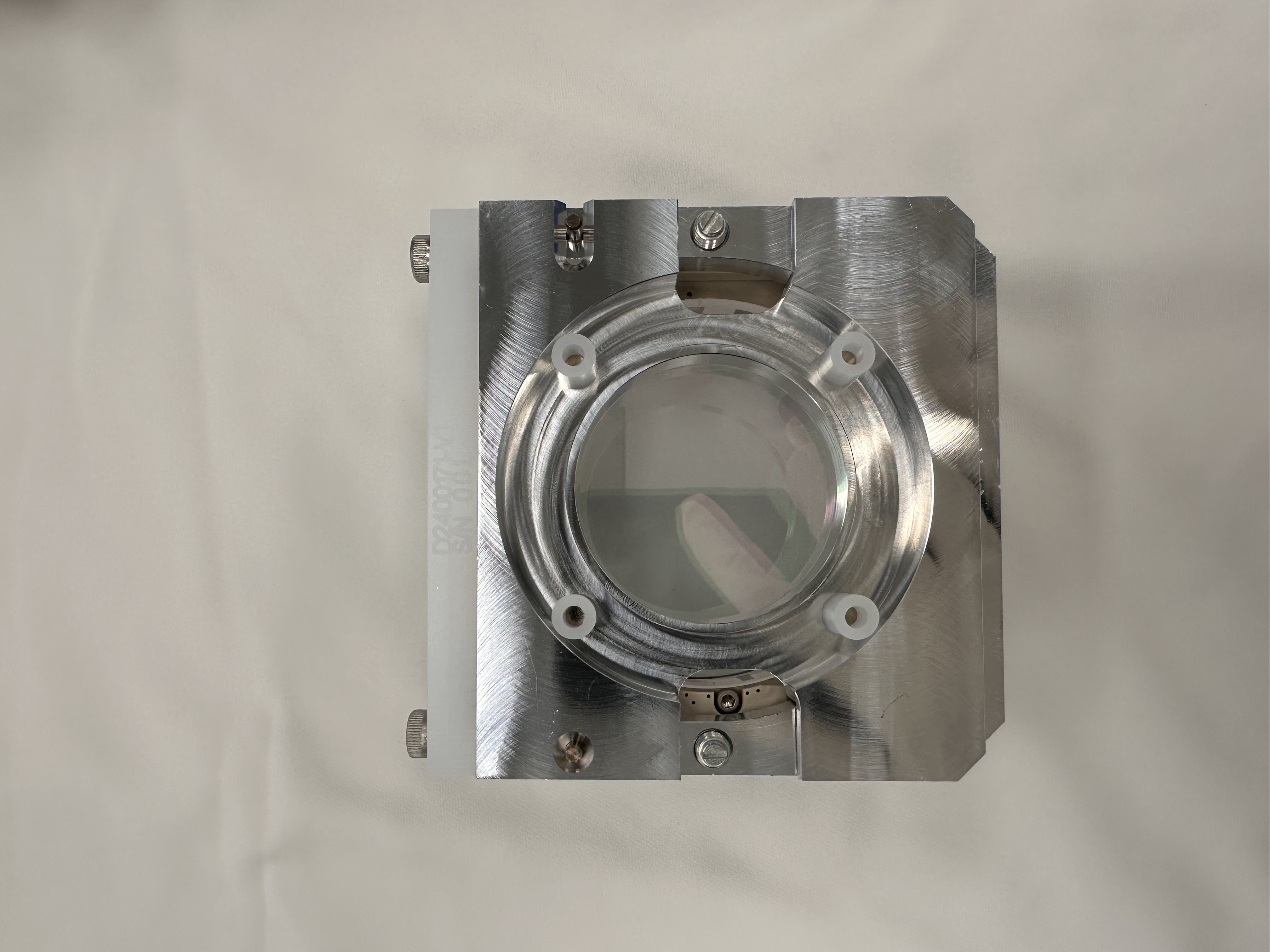
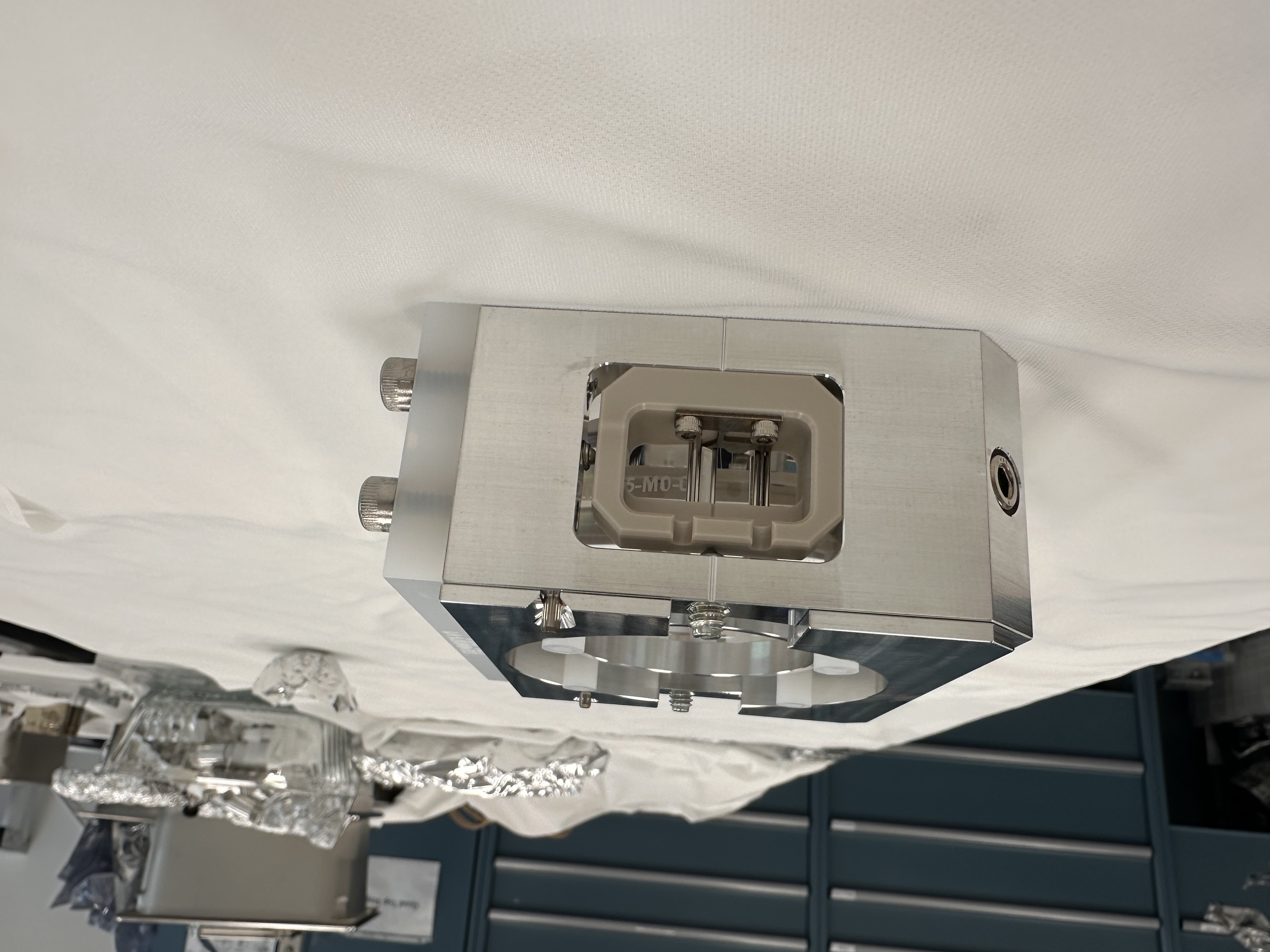
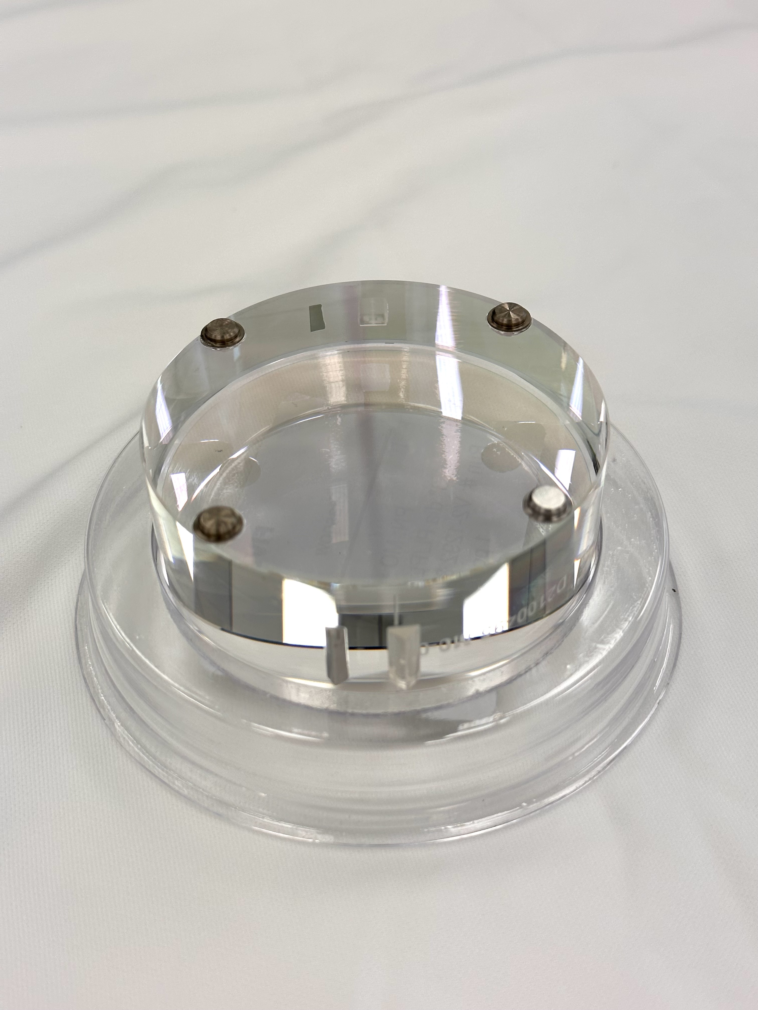
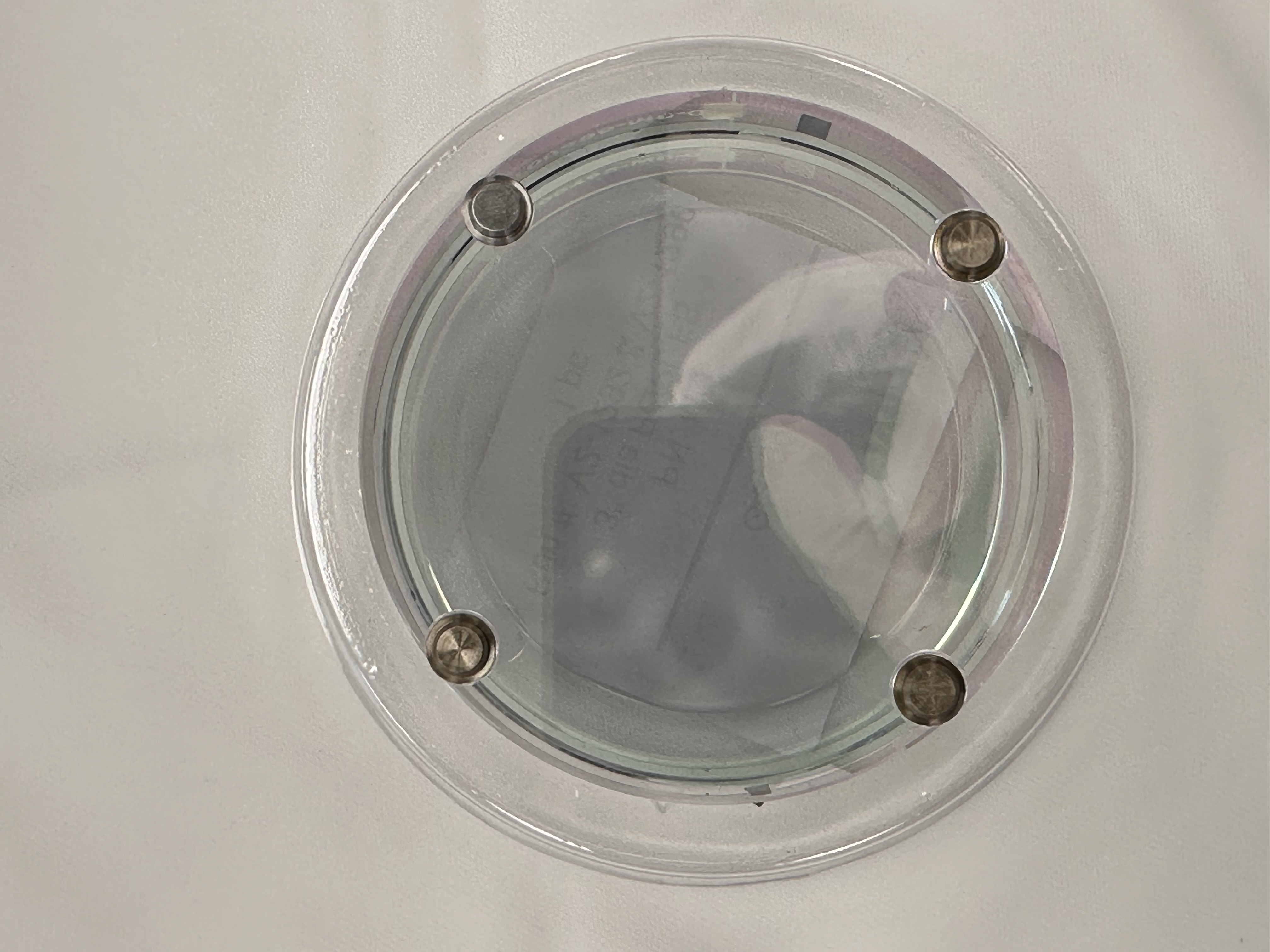
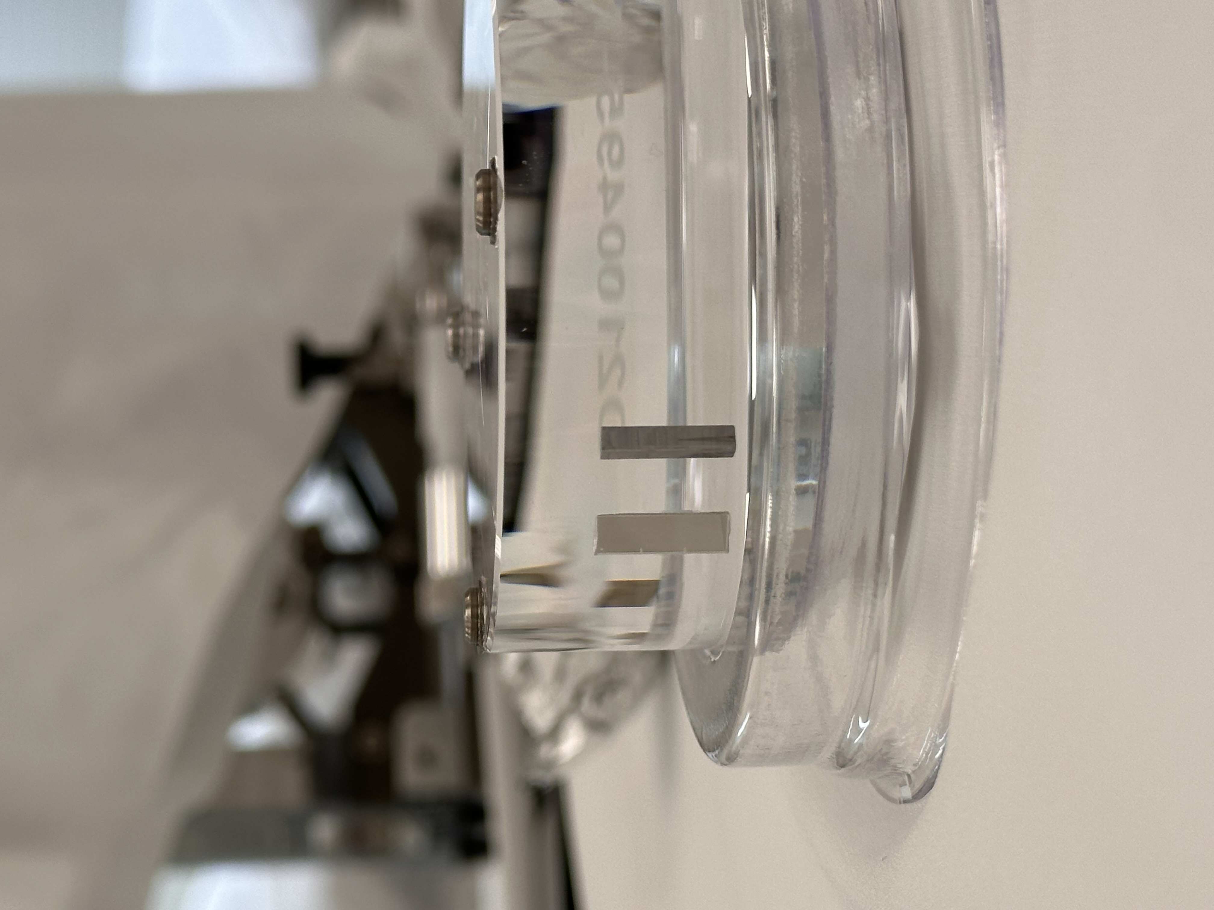
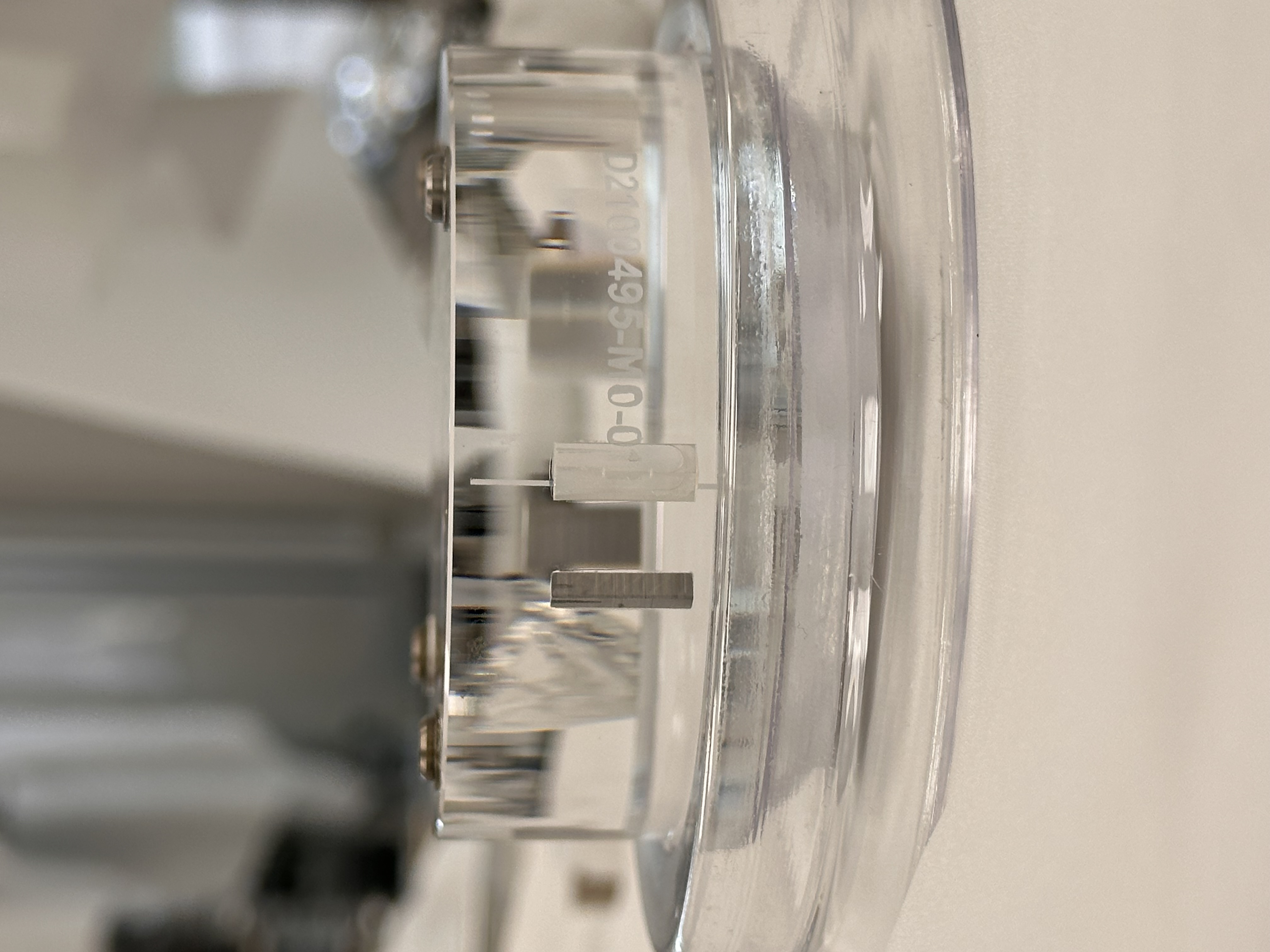
This week we glued prisms (primary - sapphire and secondary - metal) to the HRTS OM0 fused silica Optic (D2100495-V5-OM0-0001). The gluing measurement details are recorded in the DCC - google spreadsheet (T2600012), link given below,
https://caltech-my.sharepoint.com/:x:/g/personal/rmcrouch_caltech_edu/IQBWQ2S3pJX9TZYxfDaXsCvfAcJh-mrpHPS2JGNtku6Srcg
Attachment01 and attachment02 shows the prism-optic in the prism gluing jig.
Attachment03 and attachment04 shows the base for the Bosem magnet/flag glued to the AR side of the optic.
Attachment05 and attachment06 shows the two prisms glued on both the sides of the barrel of the optic. Notice that the arrow points to the HR surface and there is only one scribe line on the optic. While in the jig the arrow should be pointing down and on the right hand side of the gluing fixture (facing down).
The optic is now on its way to LLO and will be suspended in OM0 in HAM6 chamber.
Tagging for EPO.
M. Todd, C. Cahillane, K. Kawabe
In the last quarter of 2025, I was running a bunch of injections to the various ASC DOFs of the IMC, and looking at the response in the ISS --- this was all in an effort to explain the various features in the witnessed RIN from the out of loop diodes of the ISS array, or in other words create a noise budget for the ISS. In short, I believe we are IMC ASC limited below 5Hz while acheiving the shot noise limit from 20-1000Hz.
There are some peaks in the witnessed RIN that are not in the in-loop ASD, suggesting it is some noise being imposed by the loop itself. Further measurements will try and explore the source of some of these, particularly the ones around 18 and 24 Hz, with a suspicion of the IMs motion.
I wanted this alog to serve as a reference for where all the data lives for these measurements, as well as the code and noise budget plot. Note, the ISS_OUTER and INNER rin channels are saved with quick_psd, but the gpstimes are recorded in the table below.
For the projections, a transfer function is measured during the excitation of the measured DOF --- looking at the TF from the best witness channel to the ISS OUTER, and then that transfer function is applied to the witness during the quiet time when there is no excitation.
| Measurement | GPS Time | File Location | Notes |
|---|---|---|---|
| ISS OUTER RIN |
1446823543
|
/ligo/home/matthewrichard.todd/Projects/imc_injections/dtt_injections/quiet_data_iss_outer_rin.txt | Taken with quick_psd and then saved |
| ISS INNER RIN | 1446823543 | /ligo/home/matthewrichard.todd/Projects/imc_injections/dtt_injections/quiet_data_iss_inner_rin.txt | Taken with quick_psd and then saved |
| IMC PZT Pitch projection | 1446912665 | /ligo/home/matthewrichard.todd/Projects/imc_injections/dtt_injections/pzt_pit_injection_1_15_Hz.xml |
Injection Band: 1-15Hz Best Witness: WFS_A_PIT |
| IMC PZT Pitch projection | 1445107725 | /ligo/home/matthewrichard.todd/Projects/imc_injections/dtt_injections/pzt_pit_injection_15_1000_Hz.xml |
Injection Band: 15-1000Hz Best Witness: WFS_A_PIT |
| IMC PZT Yaw projection | 1446900349 | /ligo/home/matthewrichard.todd/Projects/imc_injections/dtt_injections/pzt_yaw_injection_1_15_Hz.xml |
Injection Band: 1-15Hz Best Witness: WFS_A_YAW |
| IMC PZT Yaw projection | 1445108720 | /ligo/home/matthewrichard.todd/Projects/imc_injections/dtt_injections/pzt_yaw_injection_15_1000_Hz.xml |
Injection Band: 15-1000Hz Best Witness: WFS_A_YAW |
|
IMC DOF 1 Pitch projection |
1445698453 | /ligo/home/matthewrichard.todd/Projects/imc_injections/dtt_injections/imc_dof_1_pit_injection_1_4_Hz.xml |
Injection Band: 1-4Hz Coherent Band: 0.2-5Hz Best Witness: WFS_B_PIT |
|
IMC DOF 1 Yaw projection |
1445698453 | /ligo/home/matthewrichard.todd/Projects/imc_injections/dtt_injections/imc_dof_1_yaw_injection_1_4_Hz.xml |
Injection Band: 1-4Hz Coherent Band: 0.2-5Hz Best Witness: WFS_B_YAW |
|
IMC DOF 2 Pitch projection |
1445698453 | /ligo/home/matthewrichard.todd/Projects/imc_injections/dtt_injections/imc_dof_2_pit_injection_1_4_Hz.xml |
Injection Band: 1-4Hz Coherent Band: 0.2-4Hz Best Witness: MC2_TRANS_PIT |
|
IMC DOF 2 Yaw projection |
1446303221 | /ligo/home/matthewrichard.todd/Projects/imc_injections/dtt_injections/imc_dof_2_yaw_injection_1_4_Hz.xml |
Injection Band: 1-4Hz Coherent Band: 0.2-5Hz Best Witness: WFS_A_YAW |
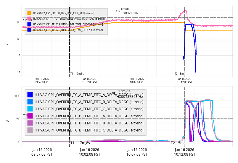
Fri Jan 16 10:12:08 2026 INFO: Fill completed in 12min 4secs
Jeff, Oli, Jonathan, EJ, Dave:
h1susaux[b13, b2h34] new models were installed, b13 for cosmetic simulink changes, h2b34 restored missing channels and needed a DAQ restart.
We did two rounds of DAQ restarts.
09:04 both legs restarted for susauxb2h34 changes. No problems.
09:56 GDS1 restart to add the three BS_M1_NOISEMON channels back into GDS. Followed by full 0-leg restart to do the same with GDS0. No problems.
Catching up on the DAC upgrades / CDS work earlier this week I updated some thresholds on the SUS SATMON screen. There were quite a few suspensions and stages to do this time so I decided to generate some code to string match and update the values for me so I don't have to spend the time copy pasting.
The script is called "satmon_update_sats_dac_upgrade.py" and its located in the same directory as SATMON. If you open it in an editor and scroll to the bottom you'll see how to use it. Here's an example line for updating PR2_M3 from a 18 to a 20 bit DAC card.
We had some hiccups in our end of day daqd restart.
1. There were duplicate channels between the h1susb13 and h1susb2h34 models. We are not sure how these got through, the daqd should have crashed on startup with an error message. We found this as it caused issues on the test framewriter on h1daqfw2.
2. After Oli removed the old block from h1susb13 we found that there were some GDS broadcaster channels that were dropped that probably shouldn't be. We removed them from the broadcast list in order to get the daqd to run. Listing the channels here so that they can be added back in tommorow:
After looking through the code, this is an old bug. It has been fixed for a while. The daqd had not been updated with the rcg for a long time due to no feature changes.
We should do a daqd package upgrade next week.

