Fil, Marc, Richard, Jeff, Oli, Erik, EJ, Jonathan, Dave:
WP12962 Move BS for upgrade to BBSS. WP12901 Upgrade ITM to LIGO-DAC
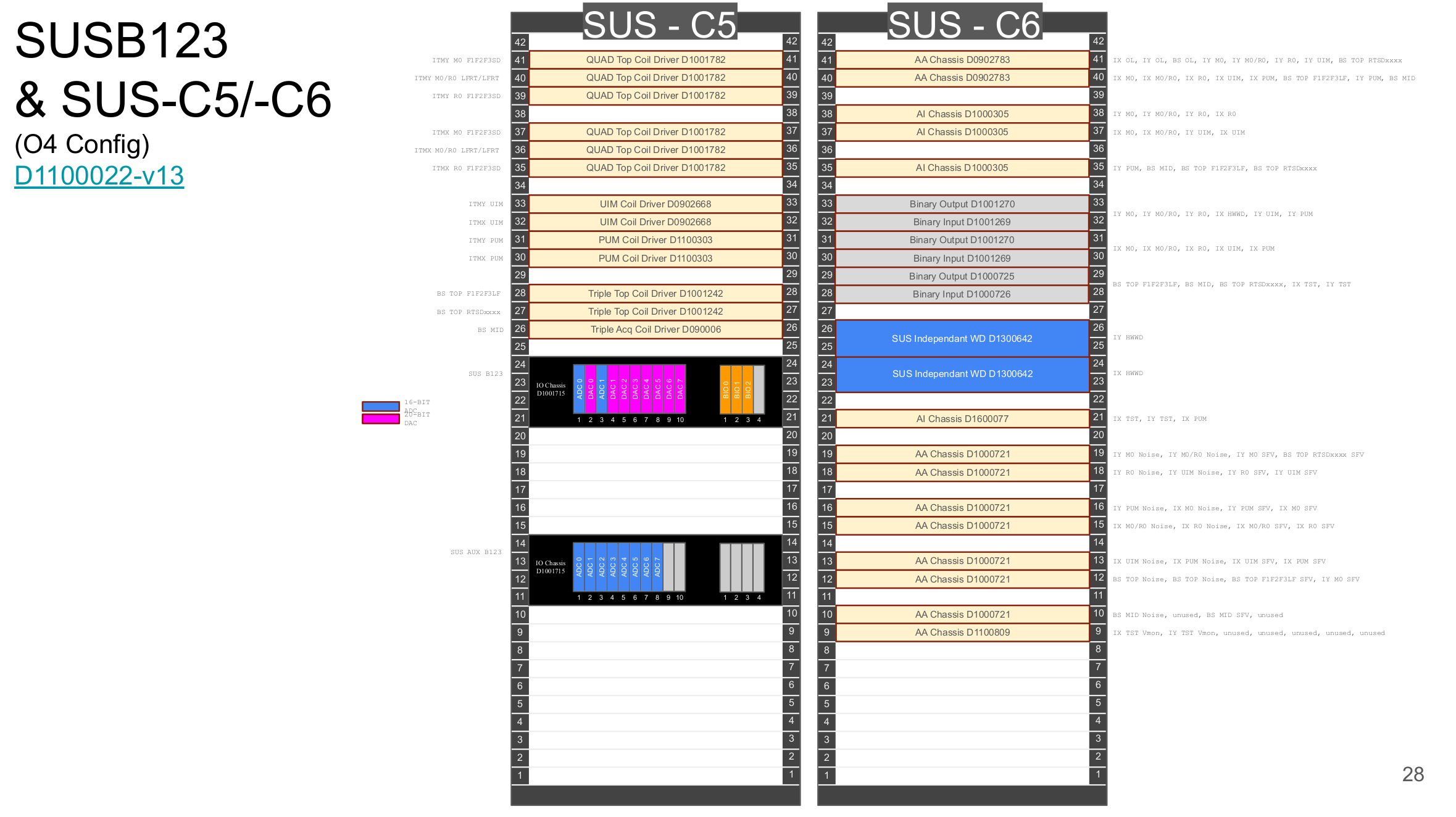
On Tuesday 13Jan2026 we reconfigured the BSC1,2,3 and HAM3,4 suspensions to move the BS control from h1susb123 to h1sush34 and upgrade the ITM test mass suspensions to use the new LIGO-DACs. Associated changes were also made to these systems' SUS-AUX frontends.
Frontend Computer Renaming:
| old name |
new name |
| h1susb123 |
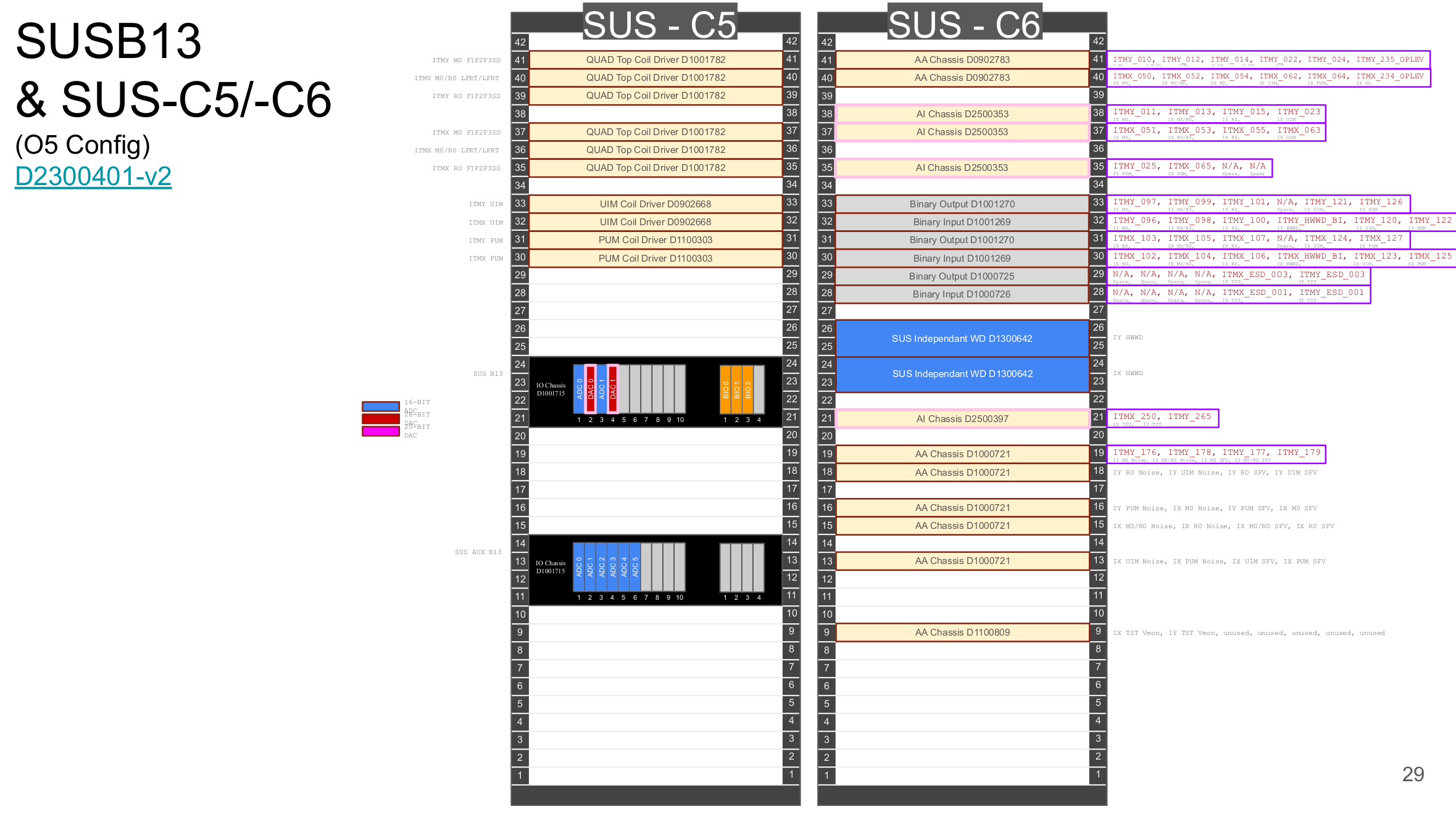
h1susb13 |
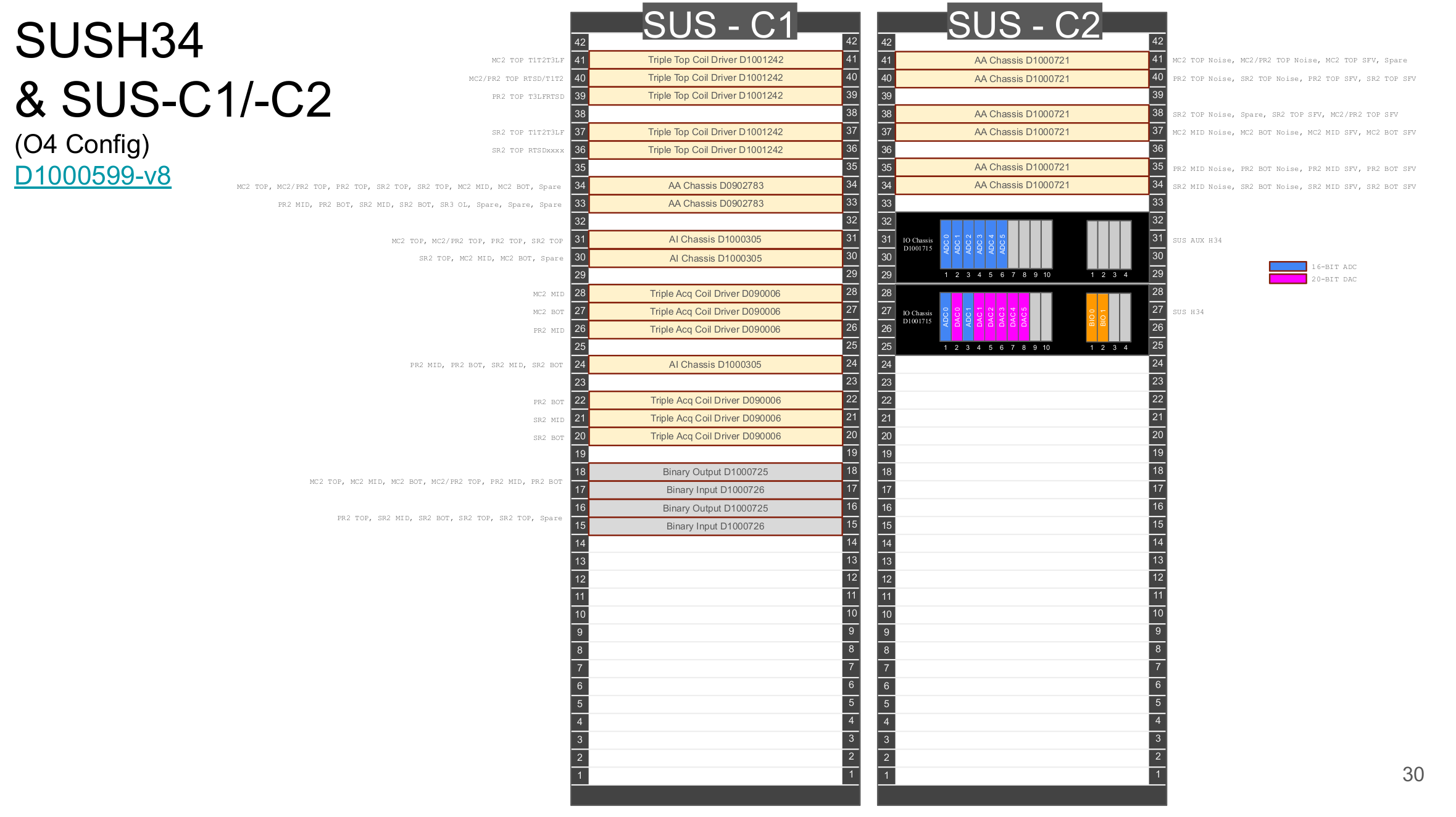
| h1sush34 |
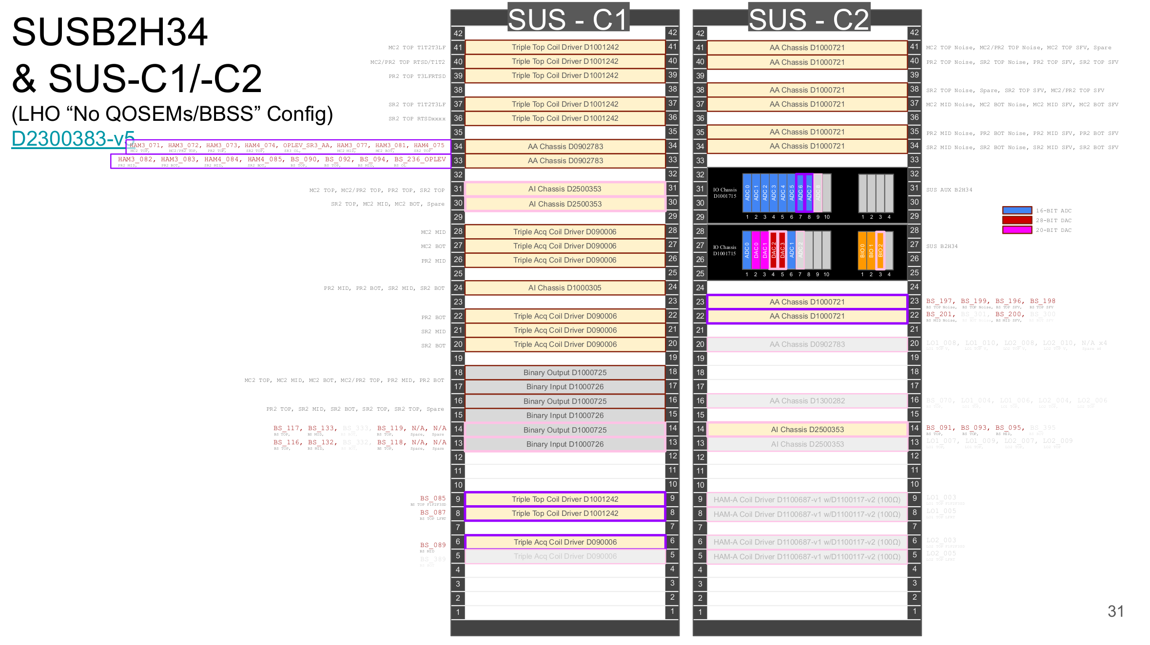
h1susb2h34 |
| h1susauxb123 |
h1susauxb13 |
| h1susauxh34 |
h1susauxb2h34 |
Prep Work:
The 4 LIGO-DACs used for this upgrade were calibrated in the EE shop and FE tested on the DTS.
The EDC was moved from h1susauxb123 to h1susauxh56
Upgrade:
The h1susb123 and h1sush34 suspensions were SDF reconcilled and put into their safe state.
The SWWD seismic systems were put into an infinite bypass.
All 4 front end were powered down and work on their IO Chassis, AAs and AIs started.
h1susb13 IO Chassis
8 20bit-DACs removed, 2 LIGO-DACs added.
Removed 20bit-DACs
| 20bit-DAC |
18/20bit-DAC Interface Card |
| 200217-17 |
S1200228 |
| 220218-29 |
S1200227 |
| 210303-49 |
S1200224 |
| 210303-35 |
S1200219 |
| 210303-22 |
S1200220 |
| 200217-19 |
S1200221 |
| 210303-57 |
S1200226 |
| 220218-08* |
S1200229 |
* 20bit-DAC 220218-08 installed in new h1susb2h34 chassis.
New Adnaco Layout
| Adnaco slot |
Card [interface] |
|
Adnaco slot |
Card [Interface] |
| A1-1 |
LIGO Timing Card |
|
A3-1 |
empty |
| A1-2 |
empty |
|
A3-2 |
empty |
| A1-3 |
ADC0 (orig) |
|
A3-3 |
empty |
| A1-4 |
LIGO-DAC0 S2500457 [010] |
|
A3-4 |
empty |
| |
|
|
|
|
| A2-1 |
ADC1 (origin) |
|
A4-1 |
BIO0 (orig) |
| A2-2 |
LIGO-DAC1 S2500448 [011] |
|
A4-2 |
BIO1 (orig) |
| A2-3 |
empty |
|
A4-3 |
BIO2 (orig) |
| A2-4 |
empty |
|
A4-4 |
empty |
h1susauxb13 IO Chassis
Removed last 2 ADCs, installed them in h1susauxb2h34 IO Chassis. ADC count went from 8 to 6.
h1susauxb2h34 IO Chassis
Added the 2 ADCs from h1susauxb13 in next available slots. ADC count went from 6 to 8.
| ADC |
ADC Card |
Interface Card |
| ADC6 |
110128-11 |
S1102417 |
| ADC7 |
110128-03 |
S1301433 |
h1susb2h34 IO Chassis
Original layout skipped Adnaco slot A2-4. Reviewed as-built drawings and alog but could not find why this slot was not being used. Assuming that there was something wrong with this slot I replaced the second Adnaco backplane
| Suspect Backplane (removed) |
C8610415 |
| New Backplane (installed) |
C8610796 |
Original layout was:
2 ADC, 5 18bit-DAC, 1 20bit-DAC, 2 BIO.
Update: keep the 2 ADCs, remove all 5 18bit-DACs, keep the 1 20bit-DAC and add a second 20bit-DAC, add 2 LIGO-DACs and add a third BIO.
Table of removed 18bit-DACs + IF
| 18bit-DAC |
Interface Card |
| 110425-10 |
S1104013 |
| 101208-71 |
S1104017 |
| 110425-04 |
S1104014 |
| 110425-09 |
S1104023 |
| 110425-46 |
* |
* Because the 18bit and 20bit DACs use the same Interface card, this IF card was left in the chassis for the second 20bit-DAC
New Adnaco layout
| Adnaco slot |
Card [Interface] |
|
Adnaco slot |
Card [Interface] |
| A1-1 |
LIGO Timing Card |
|
A3-1 |
empty |
| A1-2 |
empty |
|
A3-2 |
empty |
| A1-3 |
ADC0 (orig) |
|
A3-3 |
empty |
| A1-4 |
20bit-DAC0 (orig) |
|
A3-4 |
empty |
| |
|
|
|
|
| A2-1 |
ADC1 (orig) |
|
A4-1 |
BIO0 (orig) |
| A2-2 |
20bit-DAC1 * |
|
A4-2 |
BIO1 (orig) |
| A2-3 |
LIGO-DAC0 S2500454 [012] |
|
A4-3 |
BIO2 ADRBS96001188 |
| A2-4 |
LIGO-DAC1 S2500442 [013] |
|
A4-4 |
empty |
* 20bit-DAC1 ss0218-08 repurposed from h1susb123 surplus.
Timing Card Firmware Upgrade (Marc)
All 4 IO Chassis Timing Cards had a firmware upgrade. This was essential for the control frontends, which would not be able to drive the LIGO-DACs without the new firmware. The SUS-AUX TCs were upgraded as part of the general upgrade of all frontends.
| |
Tming Card Firmware Version |
| old |
1 - 0x1f0 |
| new |
2 - 0x635 |
Model Changes and Current Status
| h1iopsusb13 |
New model name, installed but needs SWWD review |
| h1susitmx |
Not running, being reworked |
| h1susitmy |
Not running, being reworked |
| h1susitmpi |
Not running, being reworked |
| h1iopsusb2h34 |
New model name, installed but needs SWWD review |
| h1susbs |
New location, not running, being reworked |
| h1susmc2 |
Not running, being reworked |
| h1suspr2 |
Not running, being reworked |
| h1sussr2 |
Not running, being reworked |
| h1iopsusauxb13 |
New model name, running and complete |
| h1susauxb13 |
Temporary model running, being reworked |
| h1iopsusauxb2h34 |
New model name, running and complete |
| h1susauxb2h34 |
Temporary model running, being reworked |
All models are being built with RCG5.5.2, which is needed to drive more than 1 LIGO-DAC.


Once again, Dust Monitor LAB2 has a "not a number" ERROR, all others OK/correct.