Displaying reports 15001-15020 of 89144.Go to page Start 747 748 749 750 751 752 753 754 755 End
Reports until 18:06, Wednesday 13 March 2024
H1 ISC (ISC)
craig.cahillane@LIGO.ORG - posted 18:06, Wednesday 13 March 2024 (76362)
Correlated noise - March 13, 2024
Camilla took some quiet time this morning (alog 76324),
so I reran the correlated noise budget.

The actual noisebudget traces here are eclectic, some old, some new, most are probably still from December.
Still we wanted to see if our correlated noise had changed since then (alog 76213), and the short answer is not really.

March 13 2024 Correlated Noise interactive svg

I couldn't tell what to make of this, so I compared it to our December 2023 correlated DARM.
Here, we can see our correlated noise floor at 500 - 600 Hz is moving slightly.  
If true, then it's probably not a thermal noise floor.

It's not so easy to tell if this is a calibration error, the calibration lines seem roughly similar between the two noise curves.
If this is true, then it's possible our laser noise is movely slightly, or it's something else entirely that is still not well-understood.
Non-image files attached to this report
H1 ISC
jennifer.wright@LIGO.ORG - posted 17:23, Wednesday 13 March 2024 - last comment - 10:59, Thursday 14 March 2024(76358)
9 and 45 MHz modulation depth up/down test ran in thermalised IFO

Craig, Jennie W.

In order to calibrate POPAIR_RF9 and RF18 PDs in terms of PRG9 and 45, we ran Craig's labutils/mod_depth_up_down_test.

We realised our mod depth up/down test from the other day was changing the gain of the POPAIR diodes to compensate the drop in optical gain as the modulation depths are changed.

We don't want this as it negates the change on the diodes we are trying to measure for our calibration.

Craig commented out these lines in the step_9 and step_45 functions.


We also were overestimating the PRG as the beam on IM4_TRANS PD was not well-centred.

In this log we stepped the alignment in lock to optimise on the IM4 TRANS QPD and the ISS array.

The mod-up-down-test was taken during low frequency measurements of new DARM.

Times RF9 was stepped down are 1394406378 GPS, then back up at 1394406438 GPS.

Times RF45 wa stepped down are 1394406448 GPS, then back up at 1394406508 GPS.

After this test Craig did more optimisation of the input alignment with IM 1 and 3.

Then I waited a bit and took another test. Both were done with a well thermalised IFO of more 10 hours lock.

Times RF9 was stepped down are 1394409674 GPS, then back up at 1394409735 GPS.

Times RF45 wa stepped down are 1394409744 GPS, then back up at  1394409804GPS.


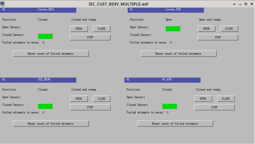
First image is beam diverter that needs unshuttered for this test.

Second image shows the plots from the first test, third image shows the second test.

Images attached to this report
Non-image files attached to this report
Comments related to this report
craig.cahillane@LIGO.ORG - 10:59, Thursday 14 March 2024 (76379)
Results from the second scan, taken starting at 1394409654 and going to 1394409887:

Channels9 MHz45 MHzCarrier
H1:IMC-PWR_IN_OUT160.0130.0150.972
H1:IMC-IM4_TRANS_NSUM_OUT160.0130.0150.972
H1:LSC-REFL_A_LF_OUT160.0400.0480.912
H1:LSC-REFL_B_LF_OUT160.0350.0420.924
H1:LSC-POP_A_LF_OUT160.0170.0080.975
H1:ASC-POP_A_NSUM_OUT160.0170.0090.975
H1:ASC-POP_B_NSUM_OUT160.0170.0080.975
H1:ASC-AS_C_NSUM_OUT160.1760.4930.331
H1:ASC-OMC_A_NSUM_OUT160.1770.6090.213
H1:ASC-OMC_B_NSUM_OUT160.1790.5390.282
H1:ASC-X_TR_A_NSUM_OUT160.0040.0060.990
H1:ASC-X_TR_B_NSUM_OUT160.0040.0060.990
H1:ASC-Y_TR_A_NSUM_OUT160.0040.0070.989
H1:ASC-Y_TR_B_NSUM_OUT160.0040.0070.989
Power-recycling gains for sidebands and carrier 9 MHz PRG = 64.7 45 MHz PRG = 27.8 Carrier PRG = 49.6 Reflection ratios for sidebands and carrier 9 MHz reflection ratio = 0.198 45 MHz reflection ratio = 0.205 Carrier reflection ratio = 0.060
H1 ISC (ISC)
craig.cahillane@LIGO.ORG - posted 17:05, Wednesday 13 March 2024 - last comment - 11:16, Thursday 14 March 2024(76359)
Input alignment changed in-lock to better align onto IM4 Trans and ISS Array
Jennie, Matt Todd, Craig

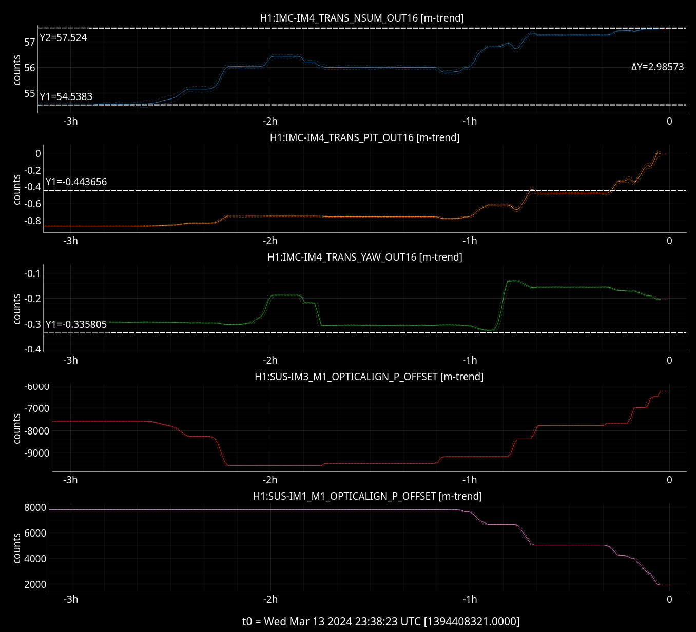
TL;DR We restored the alignment from O4a onto the ISS QPD array and IM4 Trans by moving IM1 and IM3
This has recovered the full-lock input-on-the-PRM power from 54.5 W to 57.5 W.
We are probably in a spot where we can trust Keita's IM4 TRANS calibration from alog 62213 again,
meaning we can trust our PRG of 50 W/W.


History
I tried doing this yesterday (alog 76291), but we were worried about changing the input alignment while not in lock.
Later, Sheila tried picoing onto the ISS Array (alog 76303), but undid her changes when they were causing us to fall off the array.

Alignment
Loosely, we wanted to restore the alignment we had at the end of O4a.
Centering on the ISS QPD is not necessarily the best for the alignment onto the actual ISS Array.
Additionally, the ISS QPD dofs are flipped (PIT is YAW, YAW is PIT).

I started moving IM3 and IM4 in conjunction to center the QPDs, but this didn't work because we were moving too much on the ISS QPD and not really moving on IM4 TRANS, to the point where we were falling off the diodes in the array.
So after that, I started moving IM1 and IM3 with much better results, pitching up with IM1 onto IM4 TRANS, then recovering the ISS QPD with pitching down IM3.
We ended up at the below alignments:


Epoch       GPStime         Sensor        Pitch        Yaw
---------------------------------------------------------
O4a      1389013541        ISS QPD        -0.62       0.72
                         IM4 TRANS        -0.44      -0.34

Pre-O4b  1394409800        ISS QPD        -0.54       0.75
                         IM4 TRANS        -0.02      -0.20

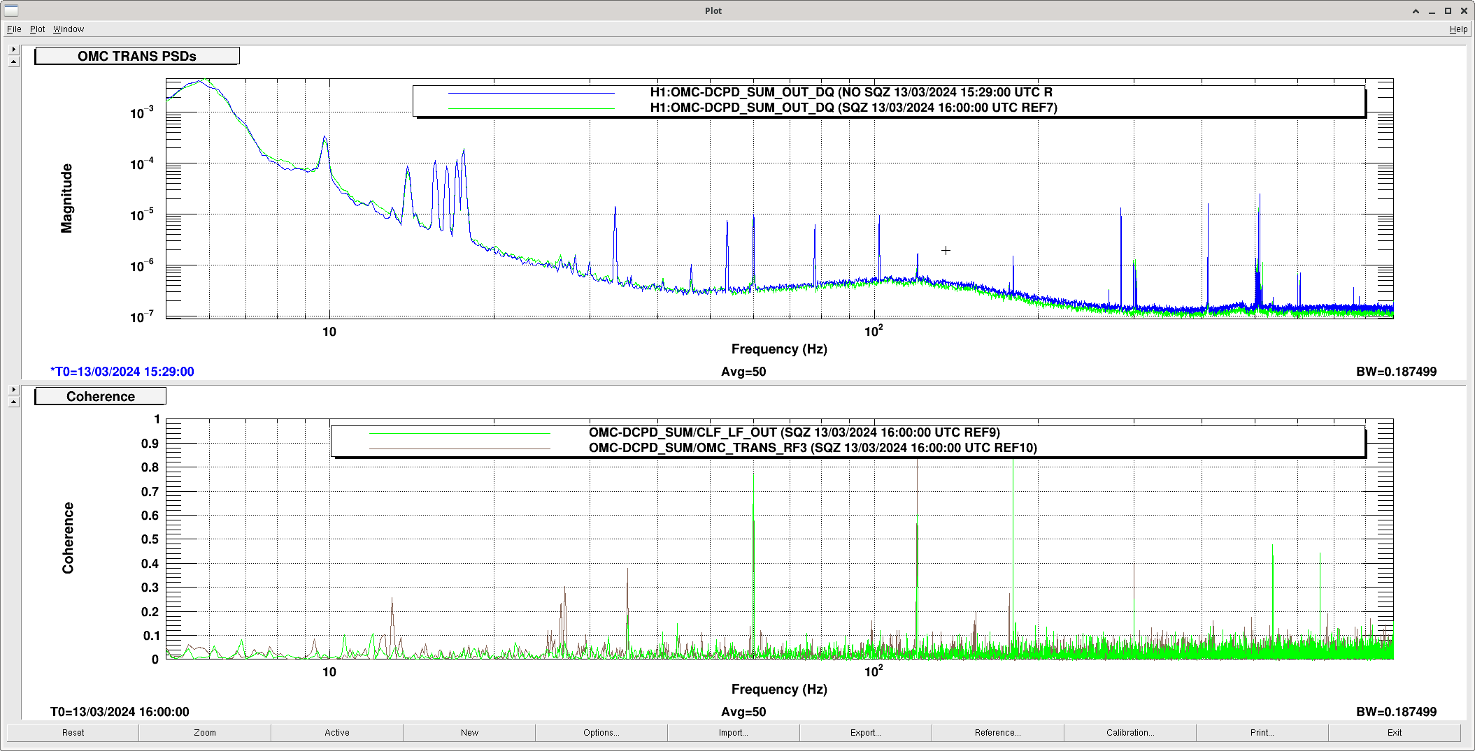
Images attached to this report
Comments related to this report
camilla.compton@LIGO.ORG - 17:30, Wednesday 13 March 2024 (76361)

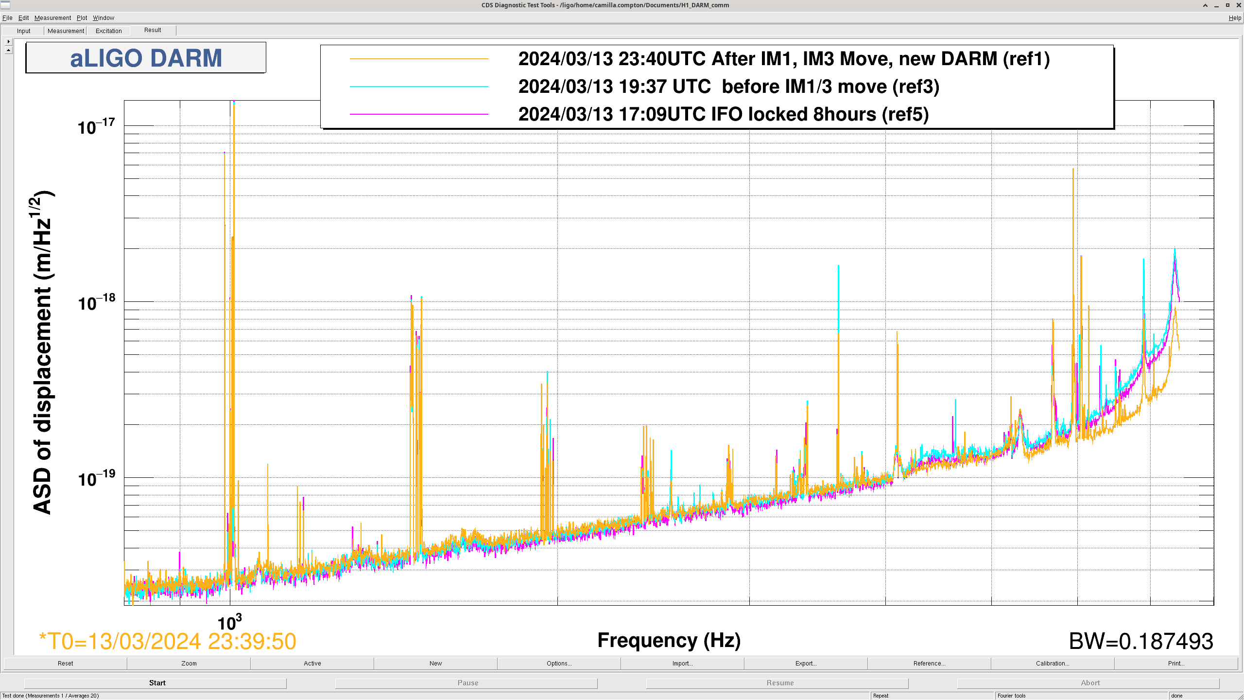
This afternoon, our high frequency DARM, above 4kHz, improved. Plot attached. This was during these IM moves, also had we swapped to the NEW_DARM configuration (so low frequency calibration is incorrect) and had moved the OMC 76335 this AM.

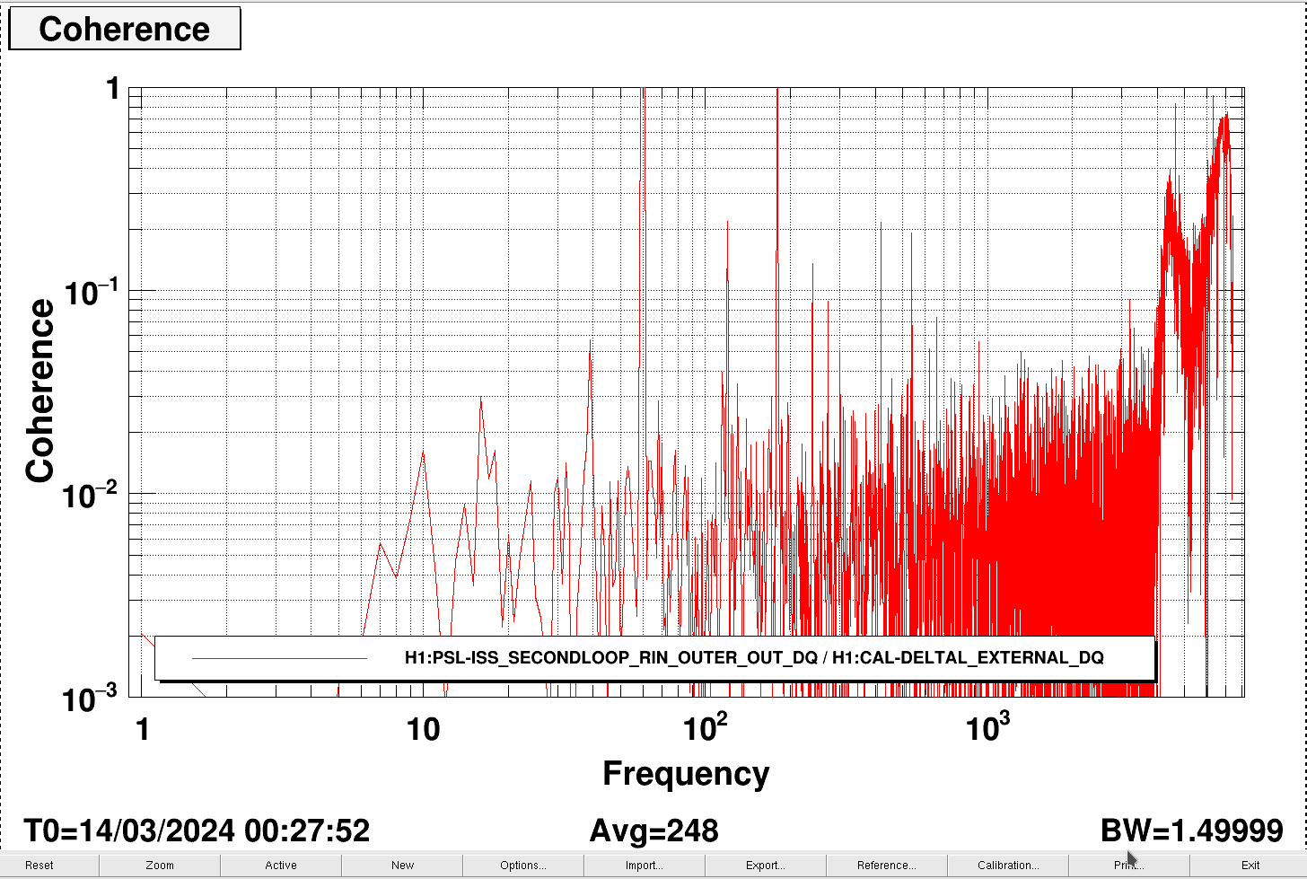
This  high frequency DARM then again increased with seemingly no IFO changes. Using the aligoNB ISS_excitation_LF.xml template with no excitation, we could show that there is high coherence between DARM and the 2nd loop ISS: plot.

Images attached to this comment
sheila.dwyer@LIGO.ORG - 08:38, Thursday 14 March 2024 (76370)

It looks like the alignment on LSC_POP changed or started clipping during this IM move. This morning TJ is reverting the IMs, (and PR3), before starting an initial alignment.

georgia.mansell@LIGO.ORG - 11:16, Thursday 14 March 2024 (76380)

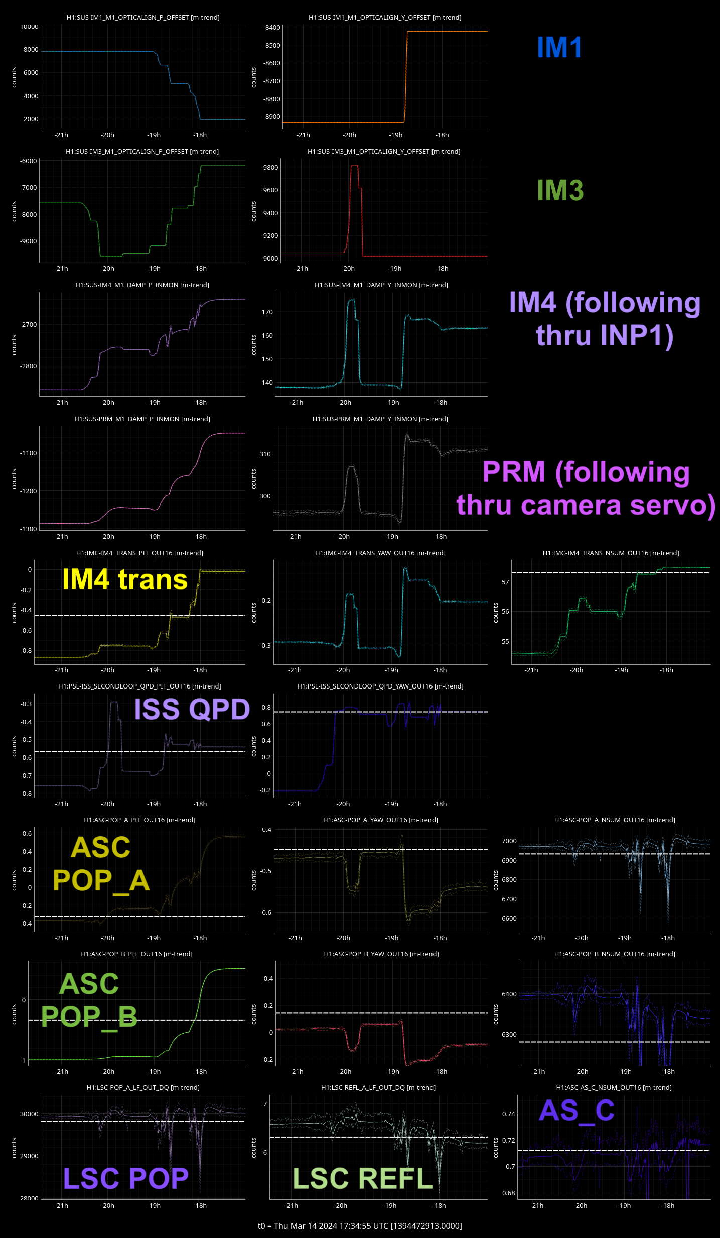
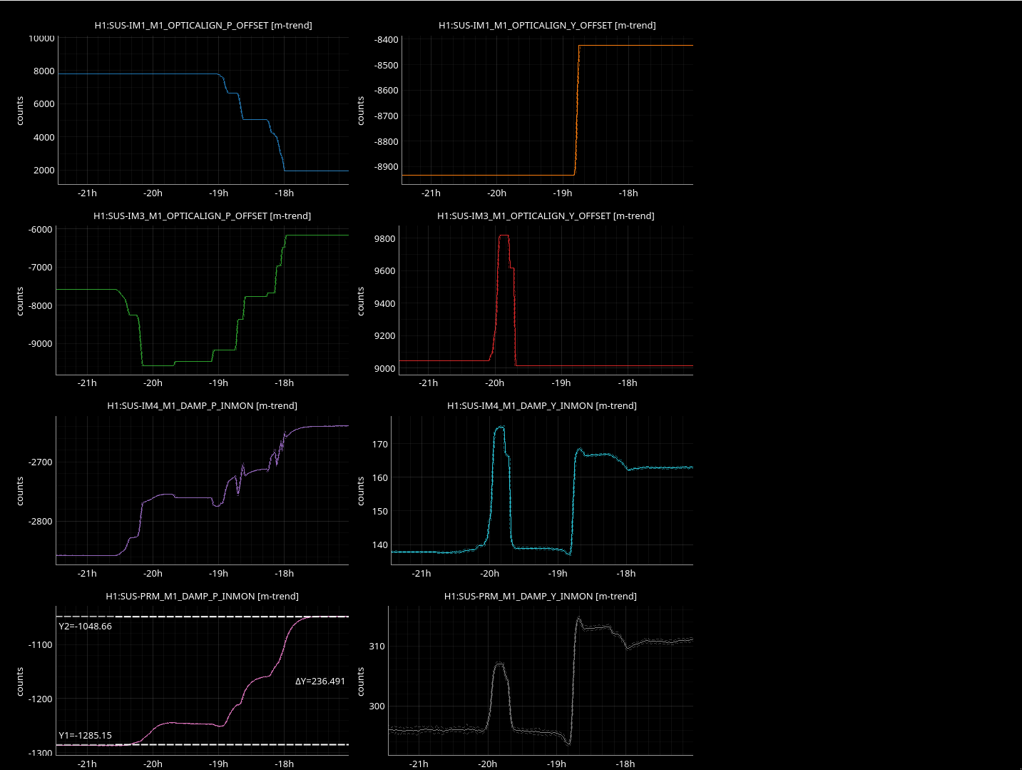
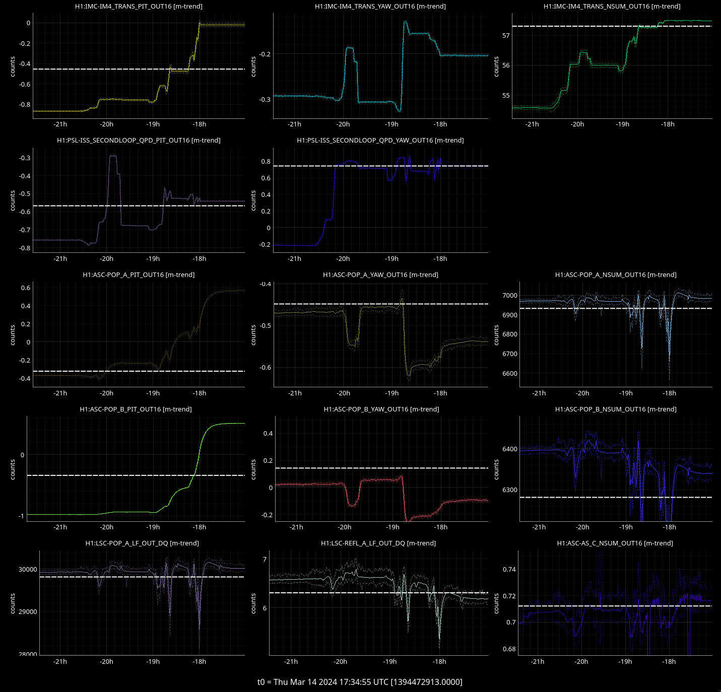
Here are some extra trends during the in-lock input beam walking yesterday.

  • Top two rows are IM1 and IM3 PIT and YAW
  • 3rd and 4th rows are IM4 and PRM driftmons as they follow the changes to IM1 and IM3
  • Below that is IM4_TRANS, the ISS QPD, ASC-POP_A, ASC-POP_B, LSC-POP, LSC-REFL and AS_C.

The cursors are where the beams were during the last lock of O4a.

There is a lot of plots so the second and third attachments are just the same plots but zoomed in to the SUS alignments, and the PD signals.

  • If the driftmons are calibrated into microradians, PRM was pitched 230 urad.
  • While stepping the alignment we ended up at the O4a spot position in PIT according to the ISS QPD, but
    • Both IM4_TRANS_PIT and ASC-POP_B_PIT started low and ended above their O4a positions
    • ASC-POP_A_PIT started close to its O4a position and ended well above
  • While stepping the alignment we wended up at the O4a spot position in YAW according to the ISS QPD, but
    • IM4_TRANS_YAW started high and got higher (the cursor for O4a reference is off the screen at -0.35), ASC-POP_A_YAW started low and ended lower, ASC-POP_B_YAW started low and ended lower.
  • As for the LSC diodes: LSC-POP ended up pretty close but a little lower than where we started, and LSC-REFL also ended lower. AS_C went up very slightly
Images attached to this comment
LHO General
ryan.short@LIGO.ORG - posted 16:03, Wednesday 13 March 2024 (76320)
Ops Day Shift Summary

TITLE: 03/13 Day Shift: 15:00-23:00 UTC (08:00-16:00 PST), all times posted in UTC
STATE of H1: Commissioning
INCOMING OPERATOR: None
SHIFT SUMMARY: Lots of good commissioning time today since H1 was locked all day (current lock stretch up to 14 hours).

LOG:

Start Time System Name Location Lazer_Haz Task Time End
15:53 FAC Mitchell LVEA - Pictures of HAM6 15:59
15:57 SAF HFD X-arm - Controlled tumbleweed burns 20:54
16:53 SQZ Nutsinee LVEA - TF at SQZ racks 17:06
17:02 FAC Karen Opt Lab - Technical cleaning 17:21
19:38 CDS Fil MX - Troubleshooting access cameras 20:38
21:06 FAC Tyler X-arm - Checking burn progress 21:17
22:49 FIT Gabriele Arms - Running Ongoing
H1 SUS
jeffrey.kissel@LIGO.ORG - posted 15:55, Wednesday 13 March 2024 - last comment - 13:22, Thursday 19 September 2024(76352)
On Filling out the new ETM and TMS Watchdog Infrastructure to Produce the Sensible, Calibrated, BLRMS signal for triggering
J. Kissel, O. Patane

A follow-up from yesterday's work on installing the infrastructure of the upgrades to the ETM and TMS watchdog systems, in this aLOG I cover with what I've filled out the infrastructure in order to obtain the calibrated BLRMS that forms the trigger signal for the user watchdog.

Remember, any sensible BLRMS system should 
    (1) Take a signal, and filter with with a (frequency) band-limiting filter, then
    (2) Take the square, then the average, then square root, i.e. the RMS, then
    (3) Low-pass the RMS signal, since only the "DC" portion of the RMS has interesting frequency content.

As a bonus, if your signal is not calibrated, then you can add 
    (0) Take the input to the band limiting filter, and calibrate it
(and through the power of linear algebra, it doesn't really matter whether you band-limit first and *then* calibrate)

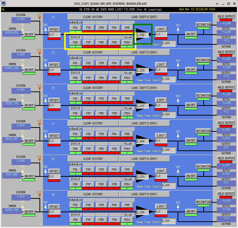
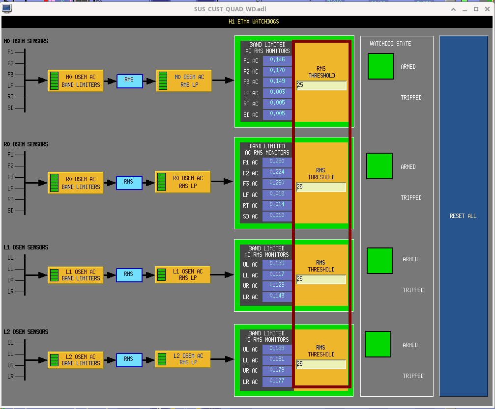
This screenshot shows the watchdog overview screen conveying this BLRMS system.

Here're the details of the BANDLIM and RMSLP filters for each of the above steps:
    (0) H1:SUS-ETMX_??_WD_OSEMAC_BANDLIM_?? 
             FM6 ("10:0.4") and FM10 ("to_um") are exact copies of the calibration filters that are, and have "always been" in the OSEMINF banks. These are highlighted in the first attachment in yellow. 
             FM6  :: ("10:0.4") :: zpk([10],[0.4],1,"n")    :: inverting the frequency response of the OSEM satellite amp frequency response
      FM10 :: ("to_um")  :: zpk([],[],0.0233333,"n") :: converting [ADC counts] into [um] assuming an ideal OSEM which has a response of 95 [uA / mm], differentially readout with 242 kOhm transimpednance and digitized with a 2^16 / 40 [ct / V] ADC.

    In addition, I also copied over the GAIN from the OSEMINF banks and copied these over as well such that each OSEM trigger signal remains "normalized" to an ideal 95 [uA / mm] OSEM. These are highlighted in dark green in the first attachment.


    (1) H1:SUS-ETMX_??_WD_OSEMAC_BANDLIM_?? 
             FM1  :: ("acBandLim") :: zpk([0;8192;-8192],[0.1;9.99999;9.99999],10.1002,"n") :: 0.1 to 10 Hz band-pass

    (2) This is a major part of the upgrade -- the front-end code that does the RMS was changed from the nonsense "cdsRms" block (see LHO:1265) to a "cdsTrueRMS" block (see LHO:19658)

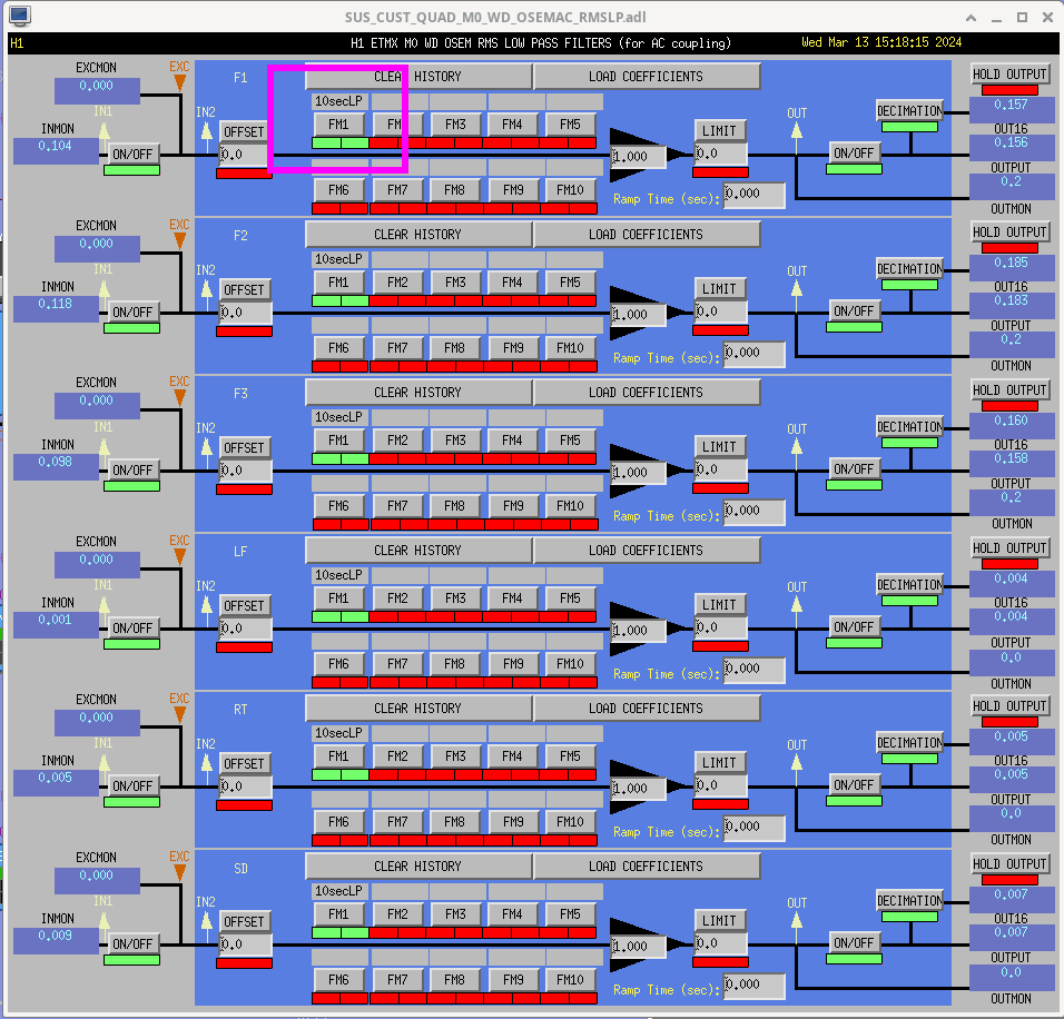
    (3) H1:SUS-ETMX_??_WD_OSEMAC_RMSLP_??
             FM1  :: ("10secLP") :: butter("LowPass",4,0.1) ::  4th order butterworth filter with a corner frequency at 0.1 Hz, i.e. a 10 second Low Pass.
        This is highlighted in magneta in the second attachment. These are direct copies from other newer suspension models that had this infrastructure in place.
           

I've committed the filter files to the userapps repo,
    /opt/rtcds/userapps/release/sus/h1/filterfiles/
        H1SUSETMX.txt
        H1SUSETMY.txt
        H1SUSETMXPI.txt
        H1SUSETMYPI.txt
        H1SUSTMSX.txt
        H1SUSTMSY.txt
are all committed as of rev 27217.

All of these settings were captured in each model's safe.snap. I've not yet accepted them in the OBSERVE.snaps.
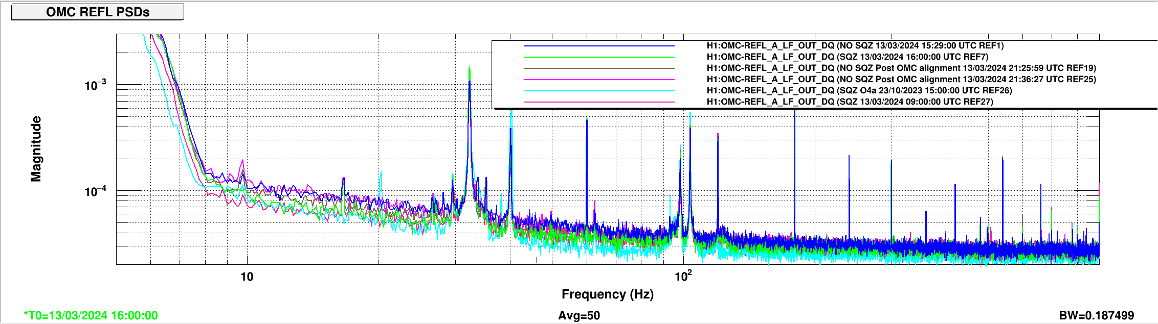
Images attached to this report
Comments related to this report
jeffrey.kissel@LIGO.ORG - 13:22, Thursday 19 September 2024 (80189)CDS, DAQ, ISC, SEI, SUS
Here's a handy script that demos using the python bindings to foton in order to easily populate simple filters from a python script.

I've only used this from the control room workstations, whose environment has been already built up for me, so I can't claim any knowledge of details about what packages this script needs. But, if you have the base cds conda environment this "should work." 
Non-image files attached to this comment
H1 SQZ (SQZ)
nutsinee.kijbunchoo@LIGO.ORG - posted 15:36, Wednesday 13 March 2024 - last comment - 15:36, Wednesday 13 March 2024(76337)
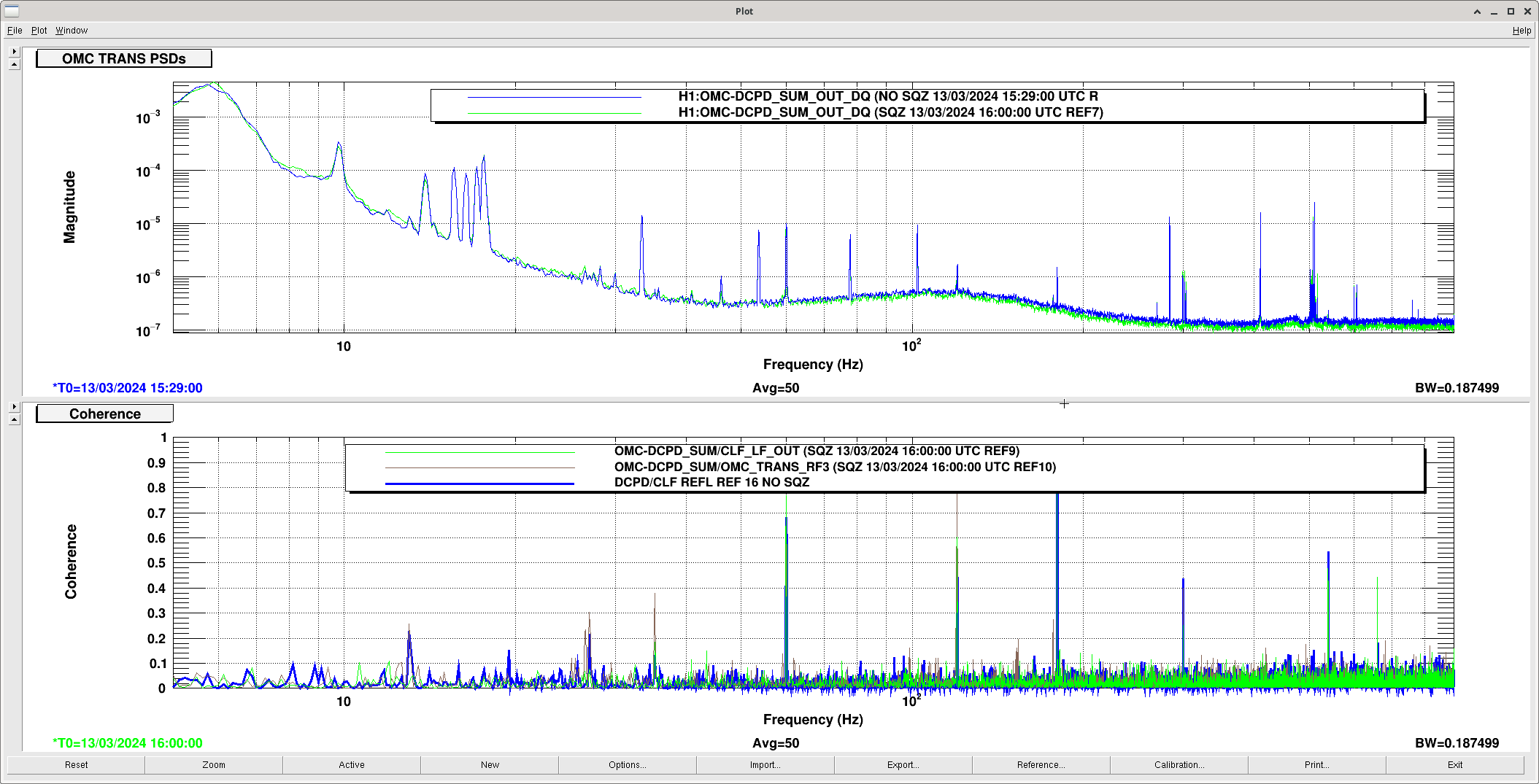
Comparing OMC_REFL with SQZ vs no SQZ

Sheila, Nutsinee

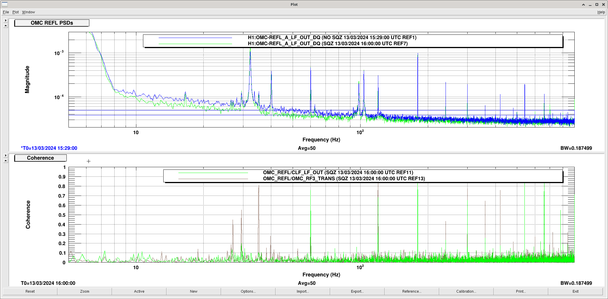
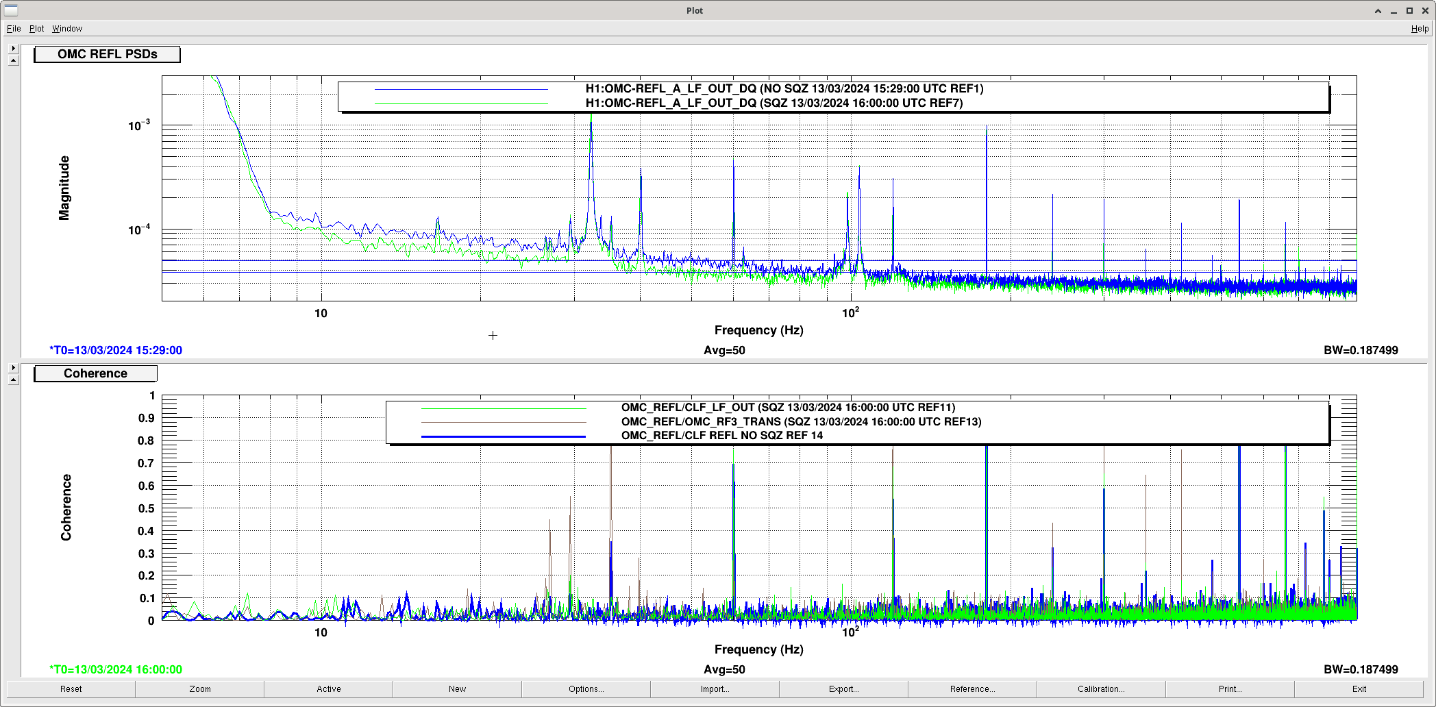
A follow up from alog76294 we want to properly compare OMC REFL when we inject squeezing and without squeezing. The noise goes up by 1.1e-5 mW (I believe this is what the channel is calibrated to) udinrg NO SQZ time compared to SQZ time.

Now including the trace from O4a and more no SQZ traces after a better OMC alignment.

After looking at more traces from SQZ and NO SQZ time it seems OMC REFL can drift up and down on its own. I don't think injecting squeezing is doing anything to OMC REFL.


The no sqz time used was 13/03/2024 15:29:00 UTC (no sqz time ends 15:51:00 UTC)

sqz time (1) used was 13/03/2024 16:00:00 UTC

sqz time (2) used was 13/03/2024 09:00:00 UTC

Post OMC alignment

no sqz time (1)  13/03/2024 21:25:59 UTC

no sqz time (2)  13/03/2024 21:36:27 UTC

O4a time 23/10/2023 15:00:00 UTC (~164Mpc)


Also attached a psd of OMC trans and a coherence between CLF and OMC RF3.

Images attached to this report
Comments related to this report
nutsinee.kijbunchoo@LIGO.ORG - 11:51, Wednesday 13 March 2024 (76338)

Some of the cohenrence with the squeezer CLF channel exists even when the beam diverter was closed.

Images attached to this comment
H1 ISC
camilla.compton@LIGO.ORG - posted 14:38, Wednesday 13 March 2024 (76349)
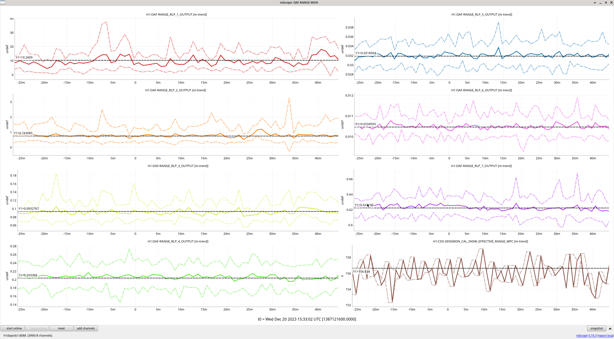
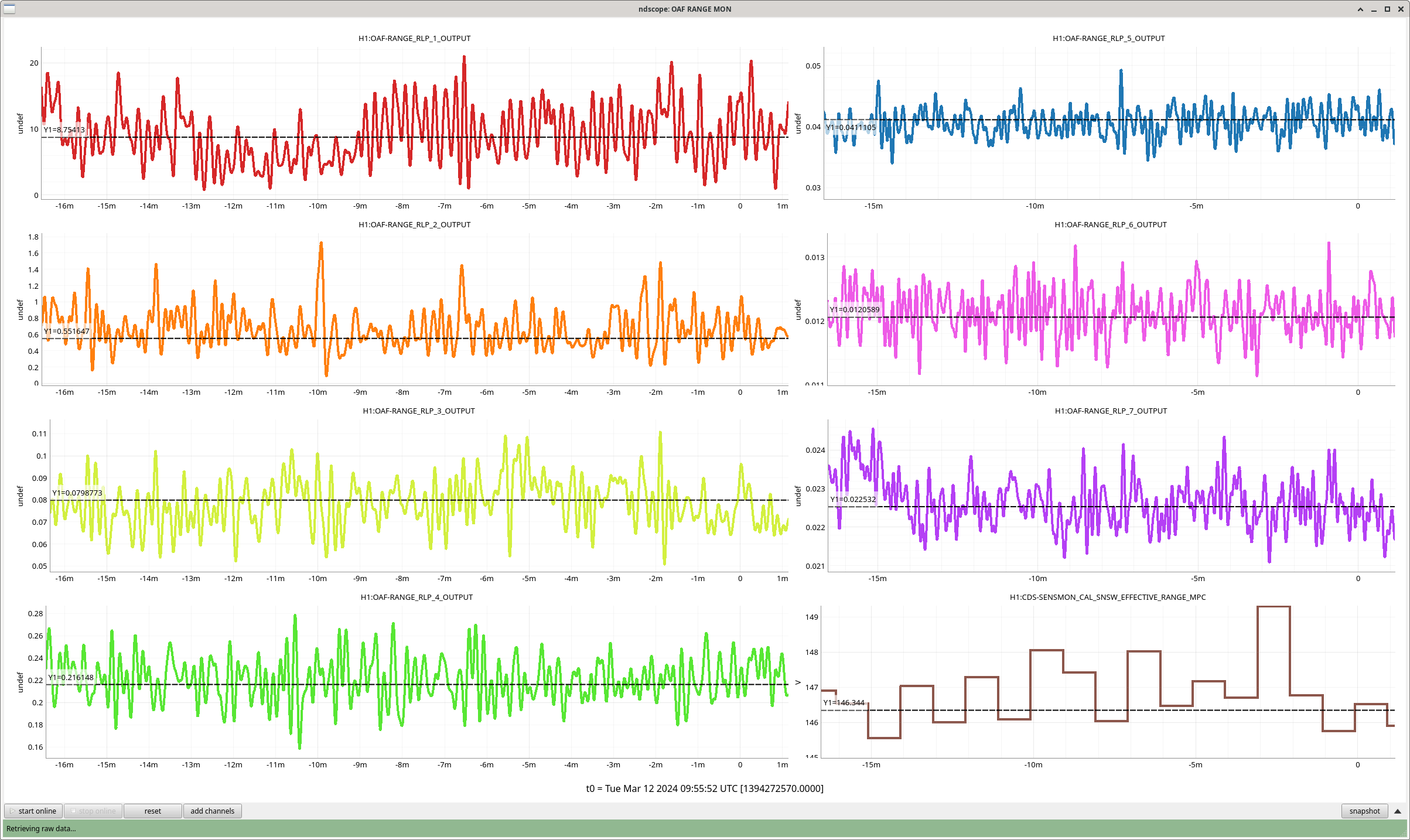
Range BLRMs comparism

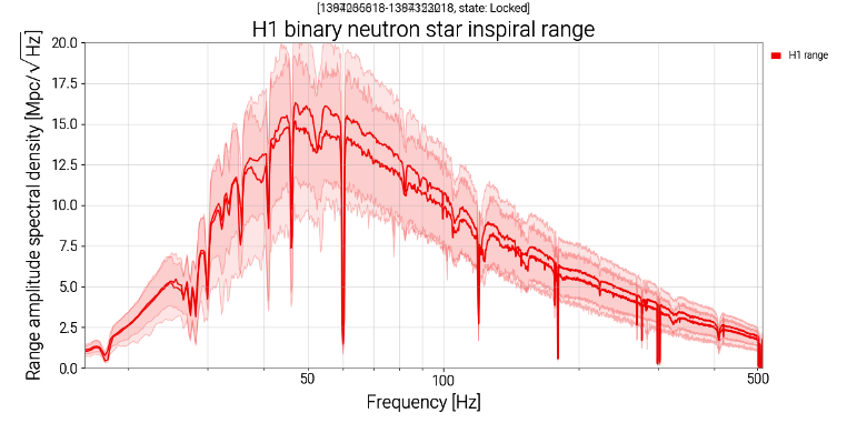
Comparing the range BLRMs from December (cold OM2 observing time used for noise budget) to now (Monday night - Tuesday 12th 10:00 UTC), BLRMs are better <60Hz and >1kHz.  BLRMS are worse in the 100-450Hz region and a little worse in the regions around this. Plot attached.

Summary pages range ASD plot shows we're now worse 35 to 500Hz: see comparison plot attached between for Dec vs Now.

Images attached to this report
H1 SUS
jeffrey.kissel@LIGO.ORG - posted 13:41, Wednesday 13 March 2024 (76347)
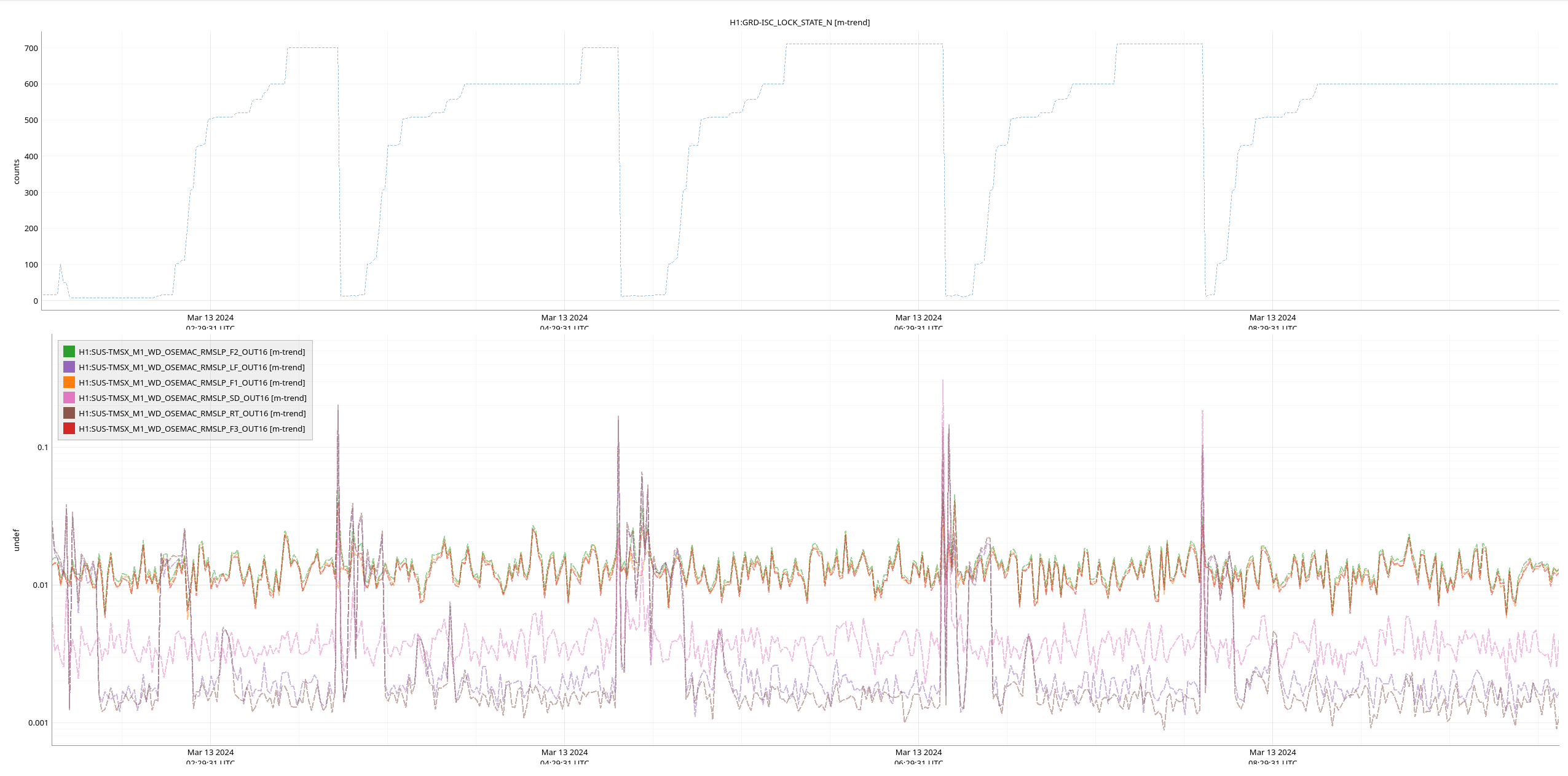
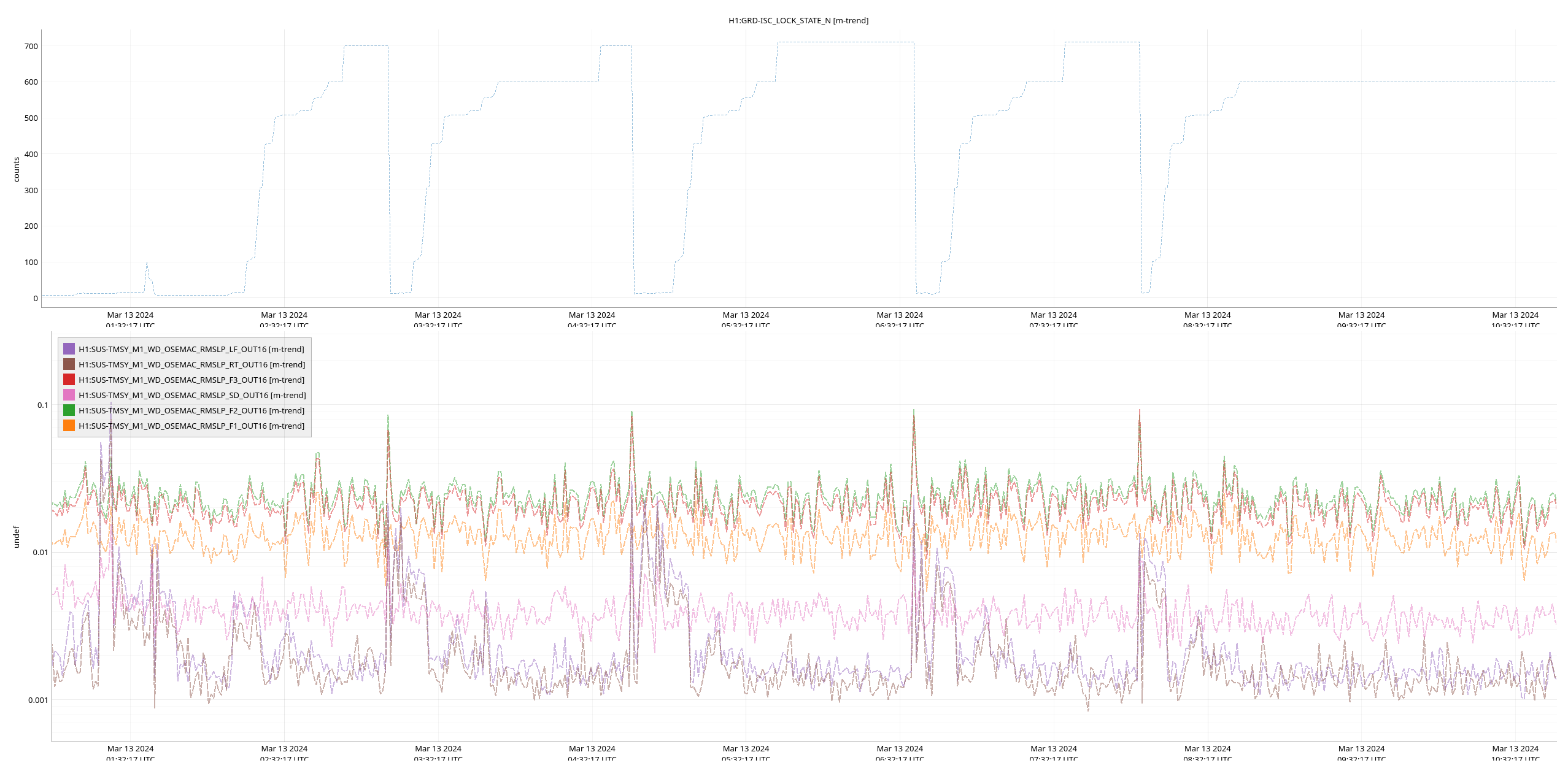
Status Report: New-and-improved WD System on TMTSs works great; Typical motion is 0.02 um_RMS, and Max motion is 0.1 um_RMS (Threshold still at 25 um_RMS)
J. Kissel

Checking the last day's worth of BLRMS values of the Transmission Monitor and Telescope Suspensions (TMTS) TMSX and TMSY M1 or top-mass OSEMs to compare against the arbitrarily chosen threshold of 25 [um_RMS] in the 0.1 - 10 Hz band -- typical values are ~0.02 [um_RMS] and maximum excursions after lock losses are 0.3 [um_RMS].

We could probably safely decrease the WD threshold to something like 1 [um_RMS].

See attached ~24 hour trend of the TMSX and TMSY BLRMS channels vs. the ISC_LOCK guardian state.
Images attached to this report
H1 SUS (CDS, ISC)
jeffrey.kissel@LIGO.ORG - posted 13:20, Wednesday 13 March 2024 - last comment - 15:21, Wednesday 13 March 2024(76343)
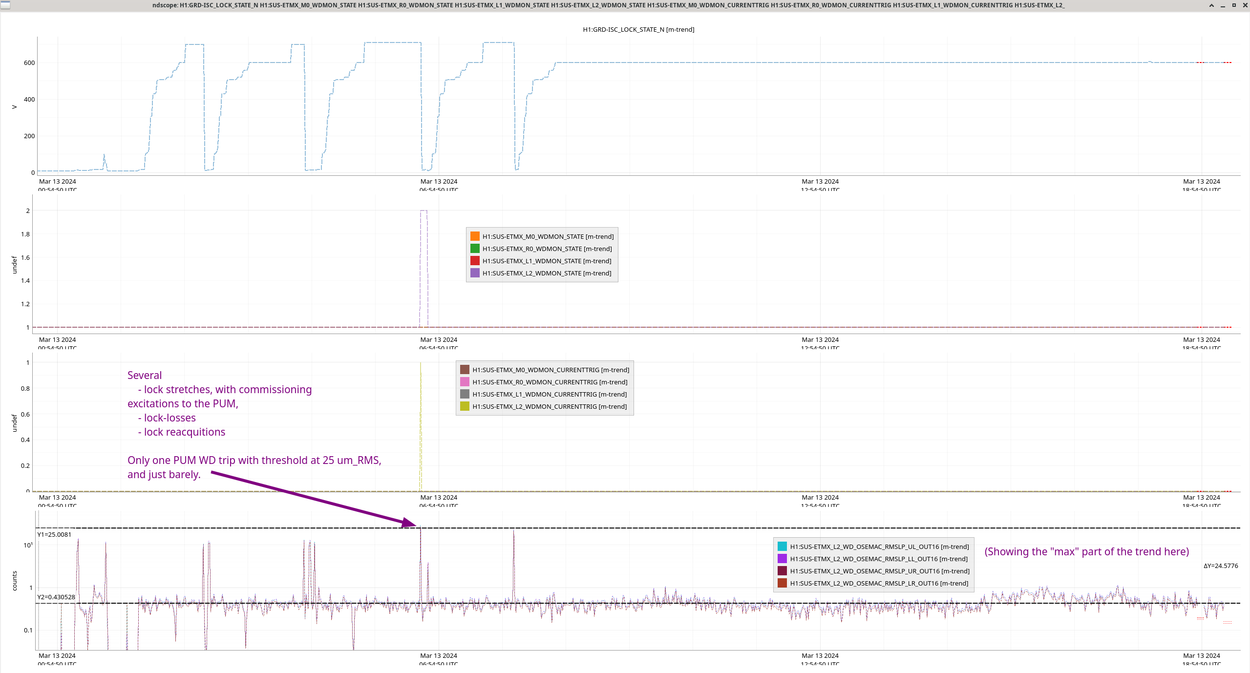
Status report: New-and-improved WD system on ETMs looks great; one WD trip at the PUM stage; threshold was arbitrary and then just barely surpassed at 25 [um_RMS]
E. Capote, L. Dartez, J. Kissel, R. Short

As you know, Oli and I installed a revamped watchdog system on the ETMs yesterday (LHO:76305). 
In doing so, we arbitrarily set the watchdog threshold for all stages at 25 [um_RMS] (over the 0.1 to 10 Hz band).

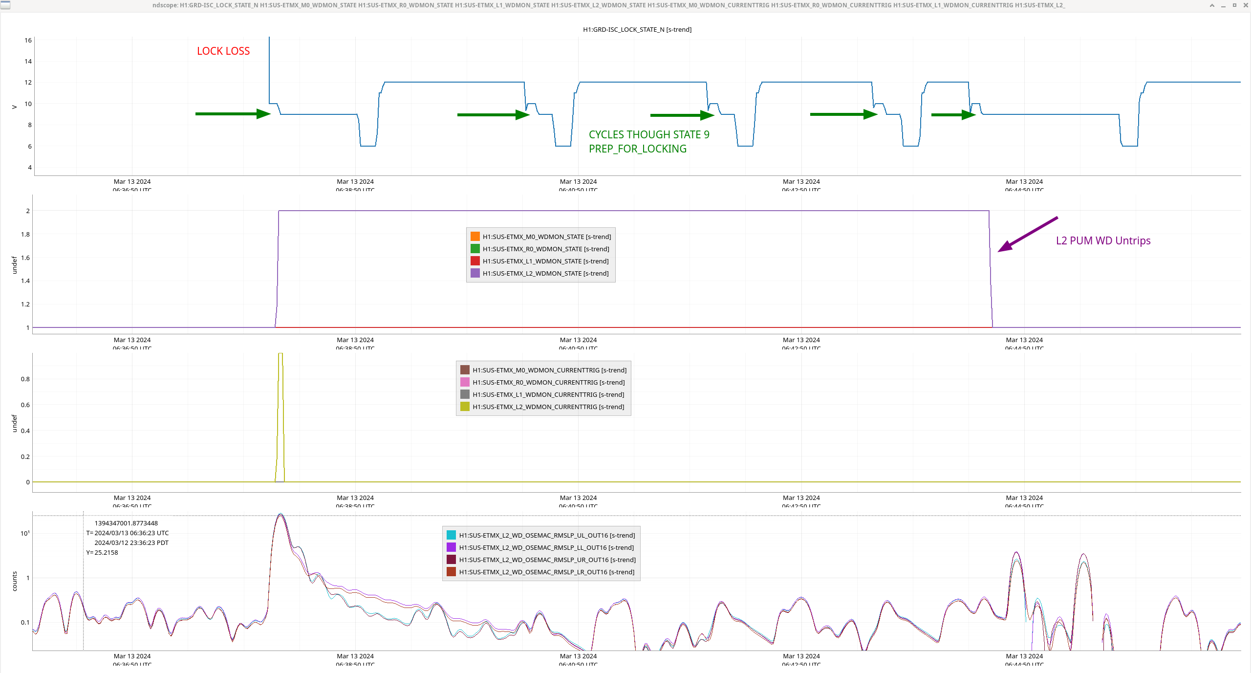
Elenna and Louis reported yesterday evening that we had *one* WD trip of the PUM stage after the lock-loss of the fourth of four successful locks (see the last phrase of the last sentence in LHO:76315). Further, they were concerned because, apparently, "the watchdog reset itself."

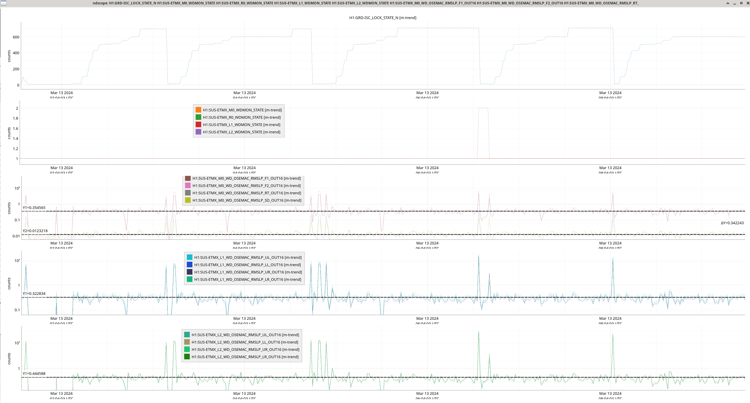
To the first point -- that there even was a watchdog trip -- the first attachment shows
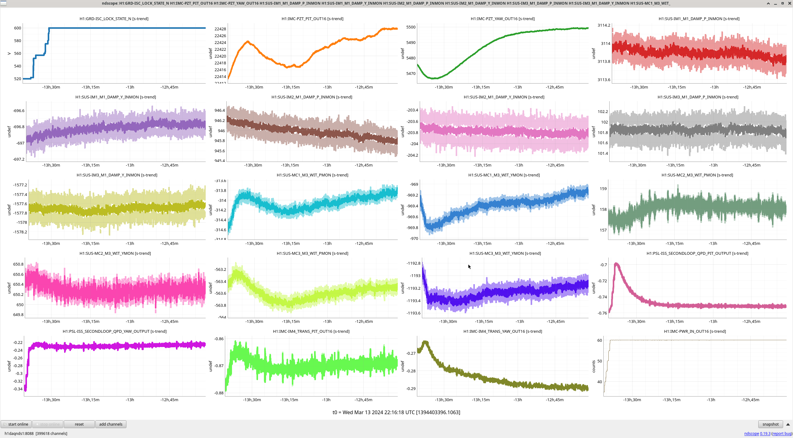
    - The ISC_LOCK guardian state (H1:GRD-ISC_LOCK_STATE_N), remeber 600 is NOMINAL_LOW_NOISE
    - The 4 stages of OSEM watchdog "is it tripped?" channels (H1:SUS-ETMX_??_WDMON_STATE, with ?? = M0, R0, L1, and L2 for Main Chain and Reaction Chain top stages, the UIM and PUM stages)
    - The 4 stages of OSEM watchdog "is the trigger actively suggesting it should be tripped?" channels (H1:SUS-ETMX_??_WDMON_CURRENTTRIG)
    - The PUM (L2) stage BLRMS trigger signals themselves, now for the first time in physical units! (H1:SUS-ETMX_L2_WD_OSEMAC_RMSLP_??_OUT16)

One can see that lock losses are typically kicking the PUM, up to 10-20 [um_RMS], but otherwise, the quiescent BLRMS is around 0.5 [um_RMS].

To the second point -- we're still investigating, but the second attachment shows that the PUM WD is reset (H1:SUS-ETMX_L2_WDMON_STATE goes from 2 to 1) at 2024-03-13 06:44:32 UTC.

In general, the guardian systems has been build on the axiom of "GUARDIAN SHALL NOT TOUCH WATCHDOGS," so we're quite suspicious of that this was not human-related. The human action that seems to be coincident with the reset on *this* lock acquisition attempt, as opposed to the three attempts immediately prior is that the ISC_LOCK guardian was taken to "INIT." It's not a smoking gun, but it's at least a bread crumb. We'll keep looking.

Finally, the third attachment shows an overall assessment of typical maximum values of the BLRMS for all stages. Here's a summary of the assessment in tabular form:

Stage        Quiescent Average Value        Maximum Transient Value
                    [um_RMS]                     [um_RMS]
M0                    0.35                         6.35
L1                    0.32                        18.34
L2                    0.44                        29.02

(where out of laziness and worry of too crowded a plot, I assume R0 has the same behavior.)

In the mean time, the watchdog is working exactly as expected, and let's bump up the PUM WD threshold to 30 [um_RMS].
Images attached to this report
Comments related to this report
ryan.short@LIGO.ORG - 15:21, Wednesday 13 March 2024 (76354)

No evidence in Guardian logs around the time of the L2 WD untripping:

$: guardctrl log -a 1394347485 -b 1394347491 | grep ETMX
2024-03-13_06:44:27.268440Z ALS_DIFF [DOWN.run] ezca: H1:SUS-ETMX_L1_LOCK_L_RSET => 2.0
2024-03-13_06:44:27.268440Z ALS_DIFF [DOWN.run] ezca: H1:SUS-ETMX_L1_DRIVEALIGN_L2P_RSET => 2.0
2024-03-13_06:44:30.704829Z ISC_LOCK [PREP_FOR_LOCKING.main] ezca: H1:SUS-ETMX_L1_LOCK_P_RSET => 2
2024-03-13_06:44:30.705395Z ISC_LOCK [PREP_FOR_LOCKING.main] ezca: H1:SUS-ETMX_L1_LOCK_Y_RSET => 2
2024-03-13_06:44:31.063310Z ISC_LOCK [PREP_FOR_LOCKING.main] ezca: H1:SUS-ETMX_L3_LOCK_P => ON: FM7
2024-03-13_06:44:32.078345Z ISC_LOCK [PREP_FOR_LOCKING.main] ezca: H1:SUS-ETMX_L3_LOCK_Y => ON: FM7
2024-03-13_06:44:32.634872Z SUS_ETMX EDGE: TRIPPED->RESET
2024-03-13_06:44:32.636179Z SUS_ETMX calculating path: RESET->ALIGNED
2024-03-13_06:44:32.642122Z SUS_ETMX new target: SAFE
2024-03-13_06:44:32.643532Z SUS_ETMX executing state: RESET (9)
2024-03-13_06:44:32.649093Z SUS_ETMX [RESET.main] Turning off all LOCK outputs
2024-03-13_06:44:32.776339Z SUS_ETMX [RESET.main] ezca: H1:SUS-ETMX_M0_LOCK_L_SW2 => 1024
2024-03-13_06:44:32.871341Z ISC_LOCK [PREP_FOR_LOCKING.main] ezca: H1:SUS-ETMX_L2_DAMP_MODE1_RSET => 2

H1 ISC
gabriele.vajente@LIGO.ORG - posted 11:32, Wednesday 13 March 2024 - last comment - 15:40, Wednesday 13 March 2024(76335)
OMC alignment in full lock

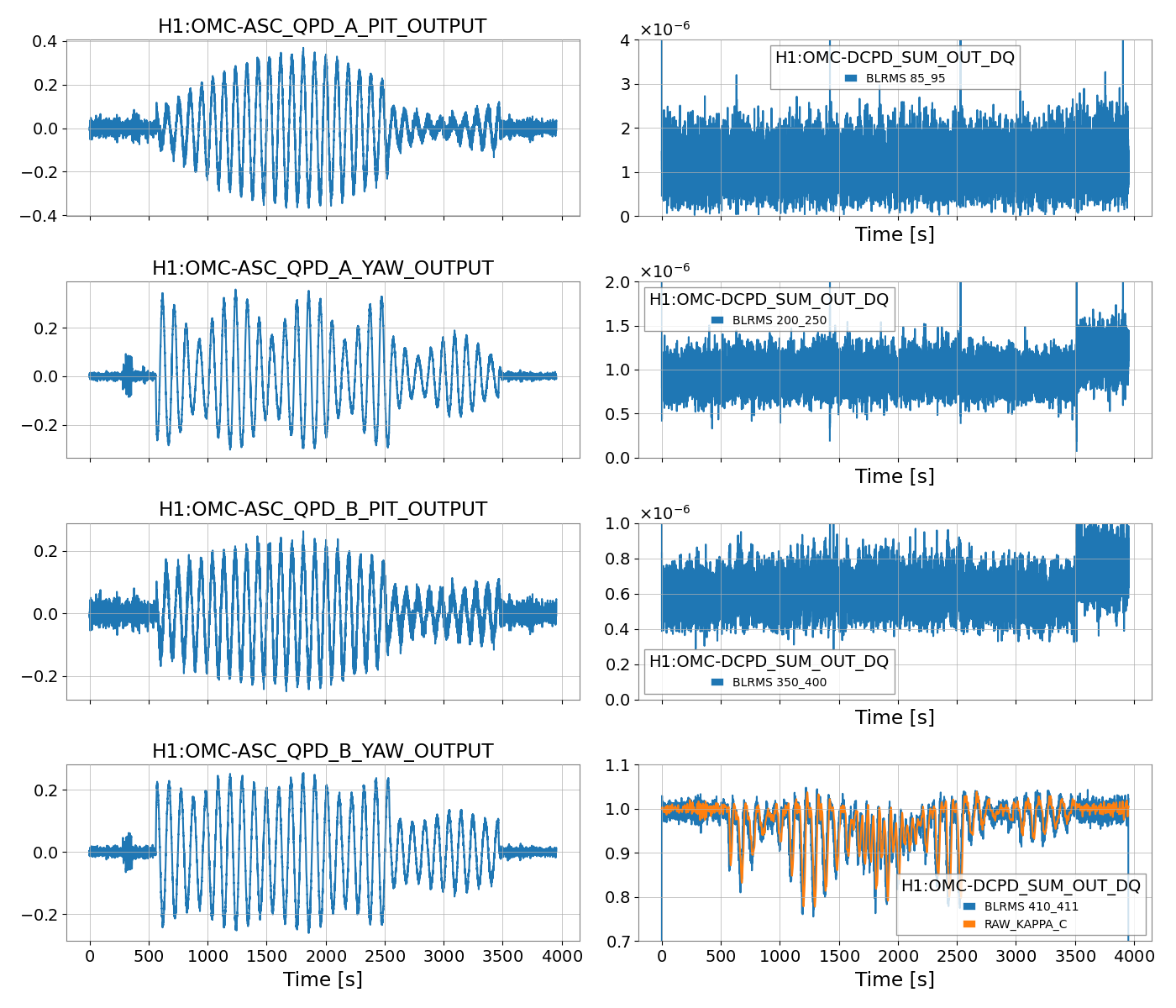
Using the low frequency line injections from this morning, we can estimate if the OMC alignment at the time was good. Note that at the time of the test, not all OMC QPD offsets were on.

The first attached plot shows a time series of the OMC QPD signals, and BLRMS in a few bands, computed on OMC-DCPD_SUM. The most interesting is the 410-411 Hz band, which track the amplitude of a DARM calibration line, the one used to compute the optical gain KAPPA_C. We see a clear large modulation of the optical gain with the OMC alignment, and the zero position for all QPD is not the one giving the highest KAPPA_C.

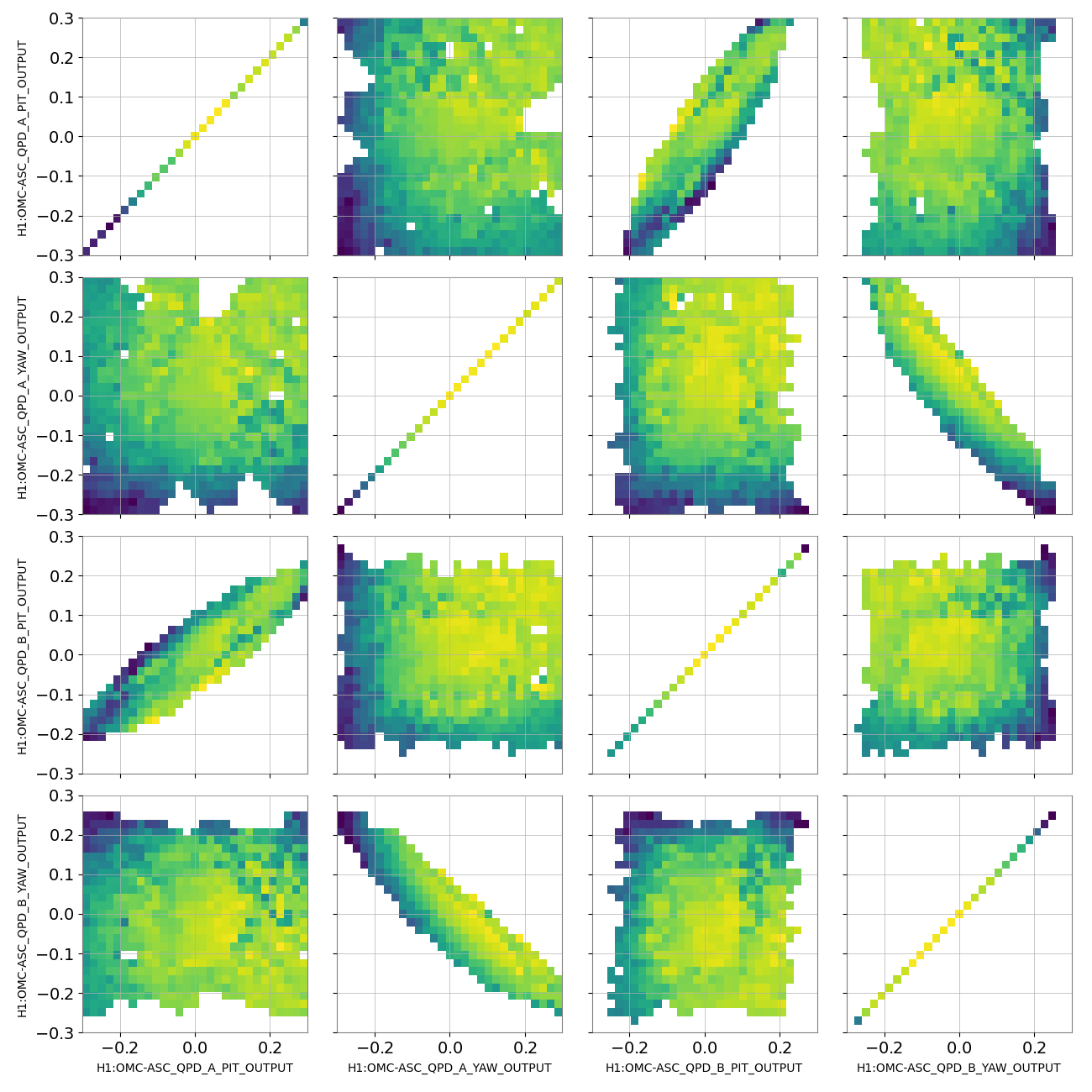
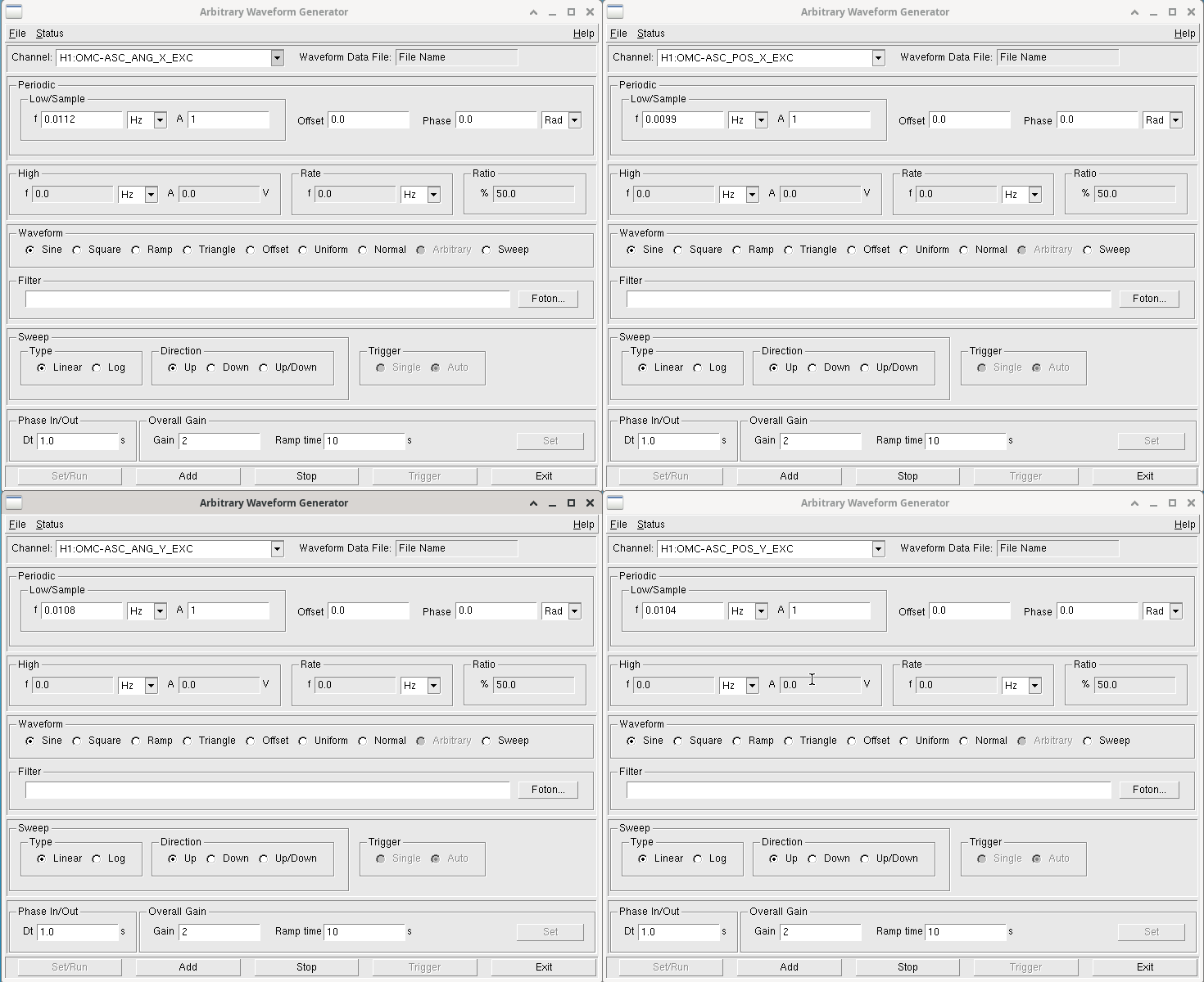
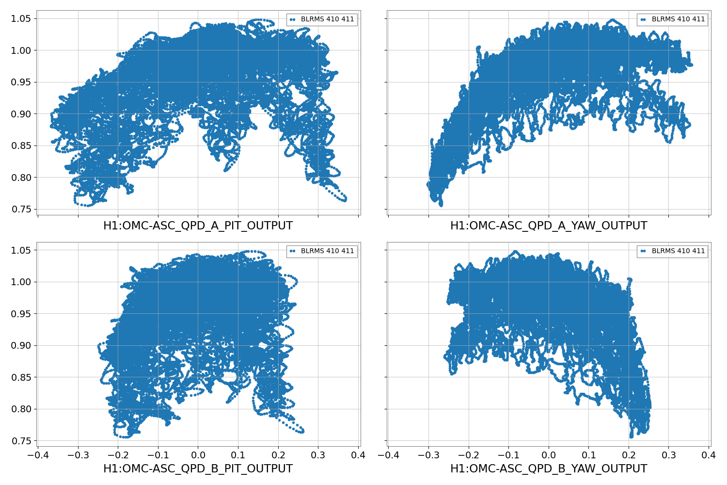
The lines were injected at slighlty different frequencies to map as well as possible the entire 4d space of OMC QPD A and B PIT and YAW. The second plot shows the BLRMS at the DARM calibration line as a function of each QPD vavlue, so four slices in this 4d space. The third plot shows two-dimensional slices, but this is somehow harder to interpreter.

Looking at the second plot, it looks like the optical gain would be improved by moving the QPD values to

QPD_A_PIT 0.1
QPD_A_YAW 0.1
QPD_B_PIT 0.05
QPD_B_YAW -0.07

to maximize the optical gain. Iterative adjustments might be needed. Also, we could inject lines ona single DOF at a time to finetune the offsets

Images attached to this report
Comments related to this report
gabriele.vajente@LIGO.ORG - 11:58, Wednesday 13 March 2024 (76340)

During the test the offsets were on for A and off for B. From the estimates above, we can guess what's the delta needed to move toward a higher optical gain, and compute new offsets

  Offsets during test Delta from measurement New suggested offsets
QPD A PIT -0.15 -0.1 -0.25
QPD A YAW 0.2 -0.1 0.1
QPD B PIT 0.0 -0.05 -0.05
QPD B YAW 0.0 0.07 0.07


elenna.capote@LIGO.ORG - 13:35, Wednesday 13 March 2024 (76345)

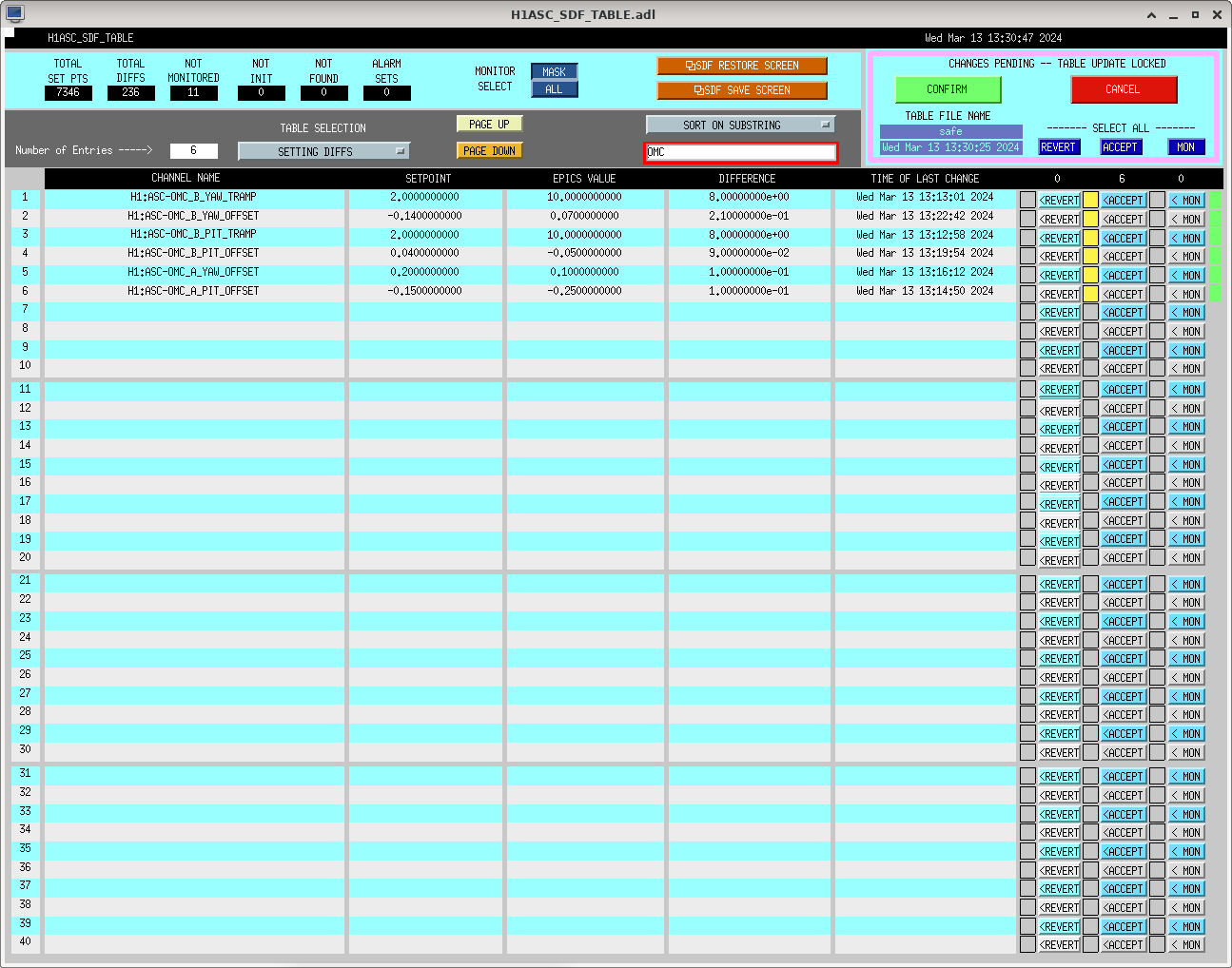
These new offsets are better, specifically we have achieved a 2.4% increase in kappa_c relative to the end of O4a (see Louis's alog). Great work team! The OMC suspension is not saturating, so all is well.

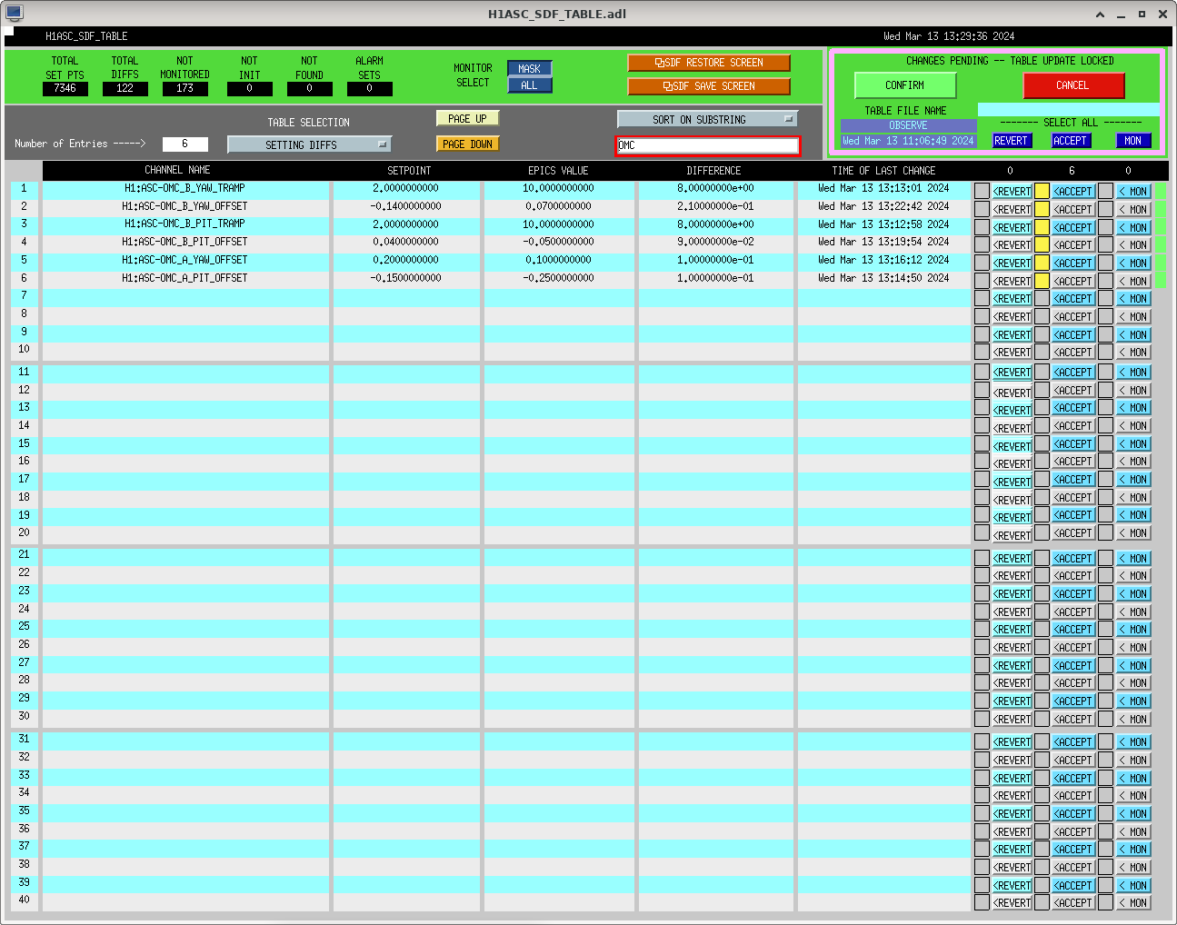
These QPD offsets have been SDFed on both observe and safe, see screenshots.

Images attached to this comment
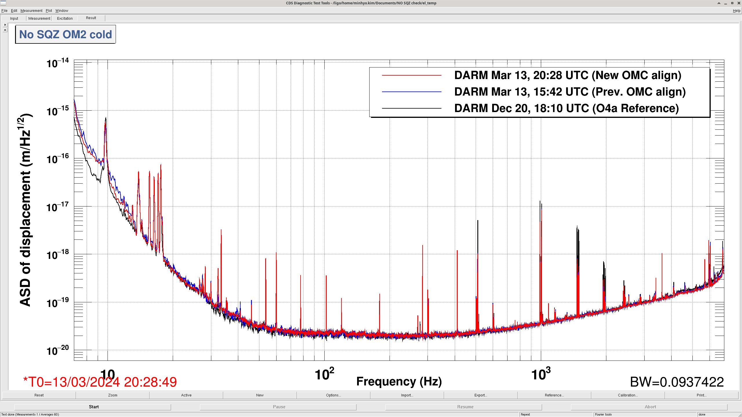
minhyo.kim@LIGO.ORG - 14:25, Wednesday 13 March 2024 (76348)

Comparison of DARM with new OMC alignment and previous one (this morning), with No SQZ + OM2 cold condition.
(Blank line is the reference of one of O4a - Dec 20, 2023 + No SQZ, cold OM2)

Noise went down compared to this morning's alignment in low frequency range.

Images attached to this comment
gabriele.vajente@LIGO.ORG - 15:40, Wednesday 13 March 2024 (76357)

Started another set of low frequency lines at 15:39 LT

Images attached to this comment
H1 SUS
oli.patane@LIGO.ORG - posted 10:11, Wednesday 13 March 2024 - last comment - 14:48, Wednesday 13 March 2024(76269)
ETM, TMS SUS models and ISI ETM models updated to replace USER DACKILL w/ better Watchdogs

Jeff K, Dave B, Oli P

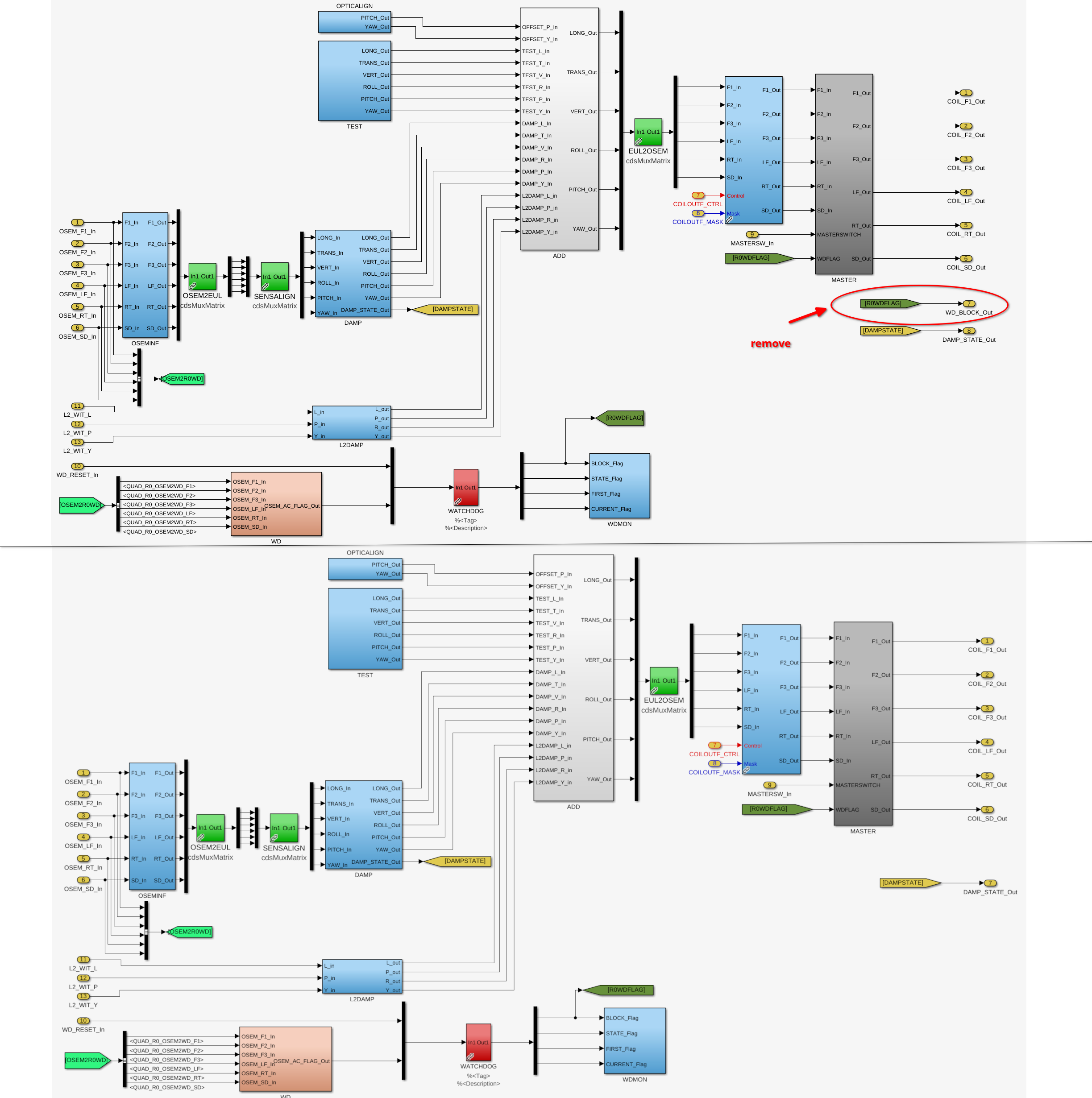
All of the optics (except OFIS, OPOS, and HXDS) were originally built with a DACKILL that will only trip if all of that suspension's Watchdogs trip. This has resulted in some problems (74545, 74622). Because of this, there has been a push to update the logic for each suspension to have an OR instead of an AND, so that the IOP DACKILL trips as soon as any one of the stages trips.
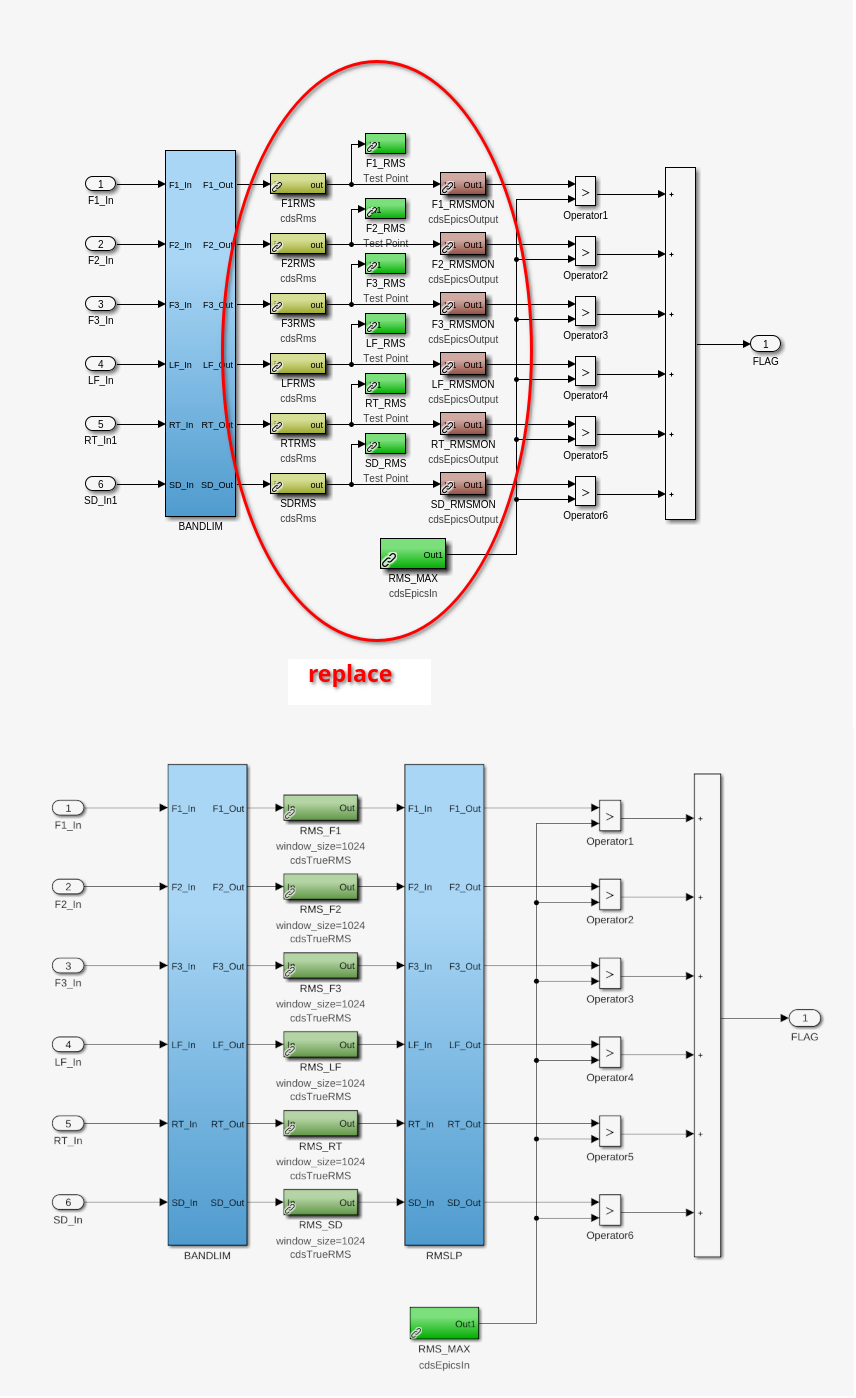
The Watchdogs for these suspensions also rely on an outdated BLRMS to figure out if the stages are saturating, and people have been wanting this to be updated since 2017(FRS9392). This update to the watchdogs would remove the need for a USER DACKILL, so now is a perfect opportunity to do both at the same time! Suspension models created after 2019 (OFIS, OPOS, HXDS, and the new HXTS) were originally made with the updated watchdogs and without the USER DACKILL, and we haven't had any issues. The changes that we made line up with what was done for these previously changed models.
Today we updated the models for the ETMs and TMSs(76305), and we will gradually be updating all of the models.
Changes made:
QUAD MASTER and TMTS Master sus models (QUAD_MASTER.mdl, TMTS_MASTER.mdl):
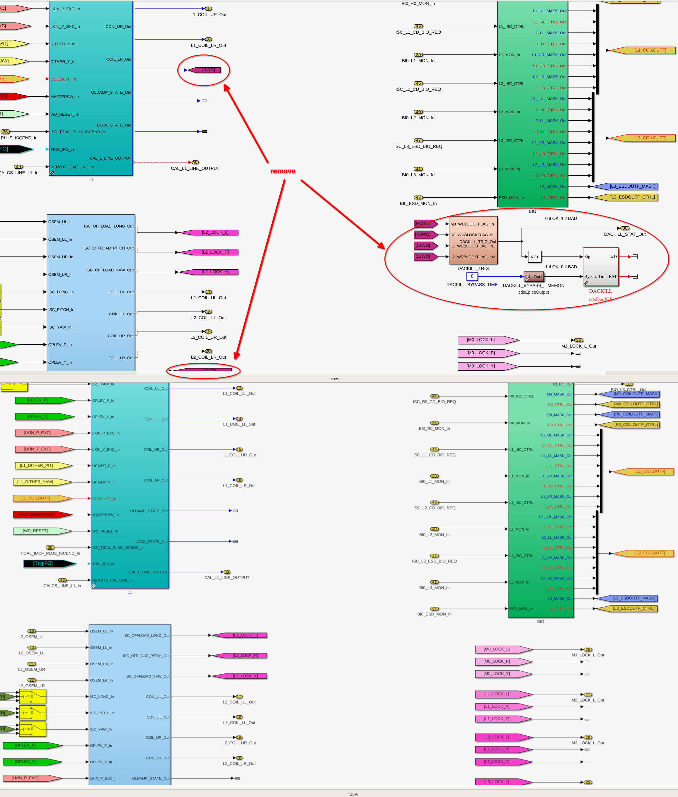
    - Top level: Removed USER DACKILL and WD block output flags(attachment1)
    - Inside each block with watchdogs: removed the watchdog flags that connect the WD RMS to the DACKILL(attachment2)
    - Inside each WD block within stage blocks: swapped the old WD BLRMS block with the better BLRMSLP block(attachment3)
Individal sus models (h1susetmx.mdl, h1susetmy.mdl, h1sustmsx.mdl, h1sustmsy.mdl):
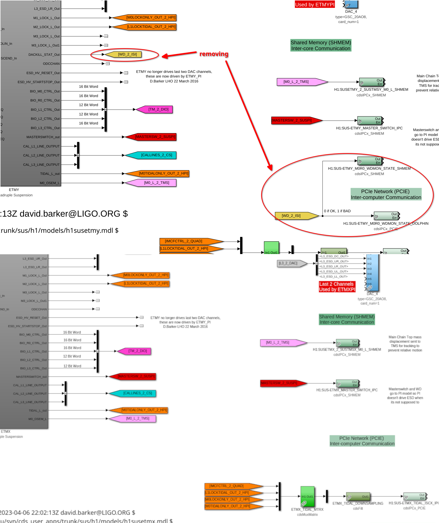
    - Removed top level WD_2_ISI output flags and connection of WD_2_ISI out to ISI model(attachment4)
Individual sus pi models(h1susetmxpi.mdl, h1susetmypi.mdl):
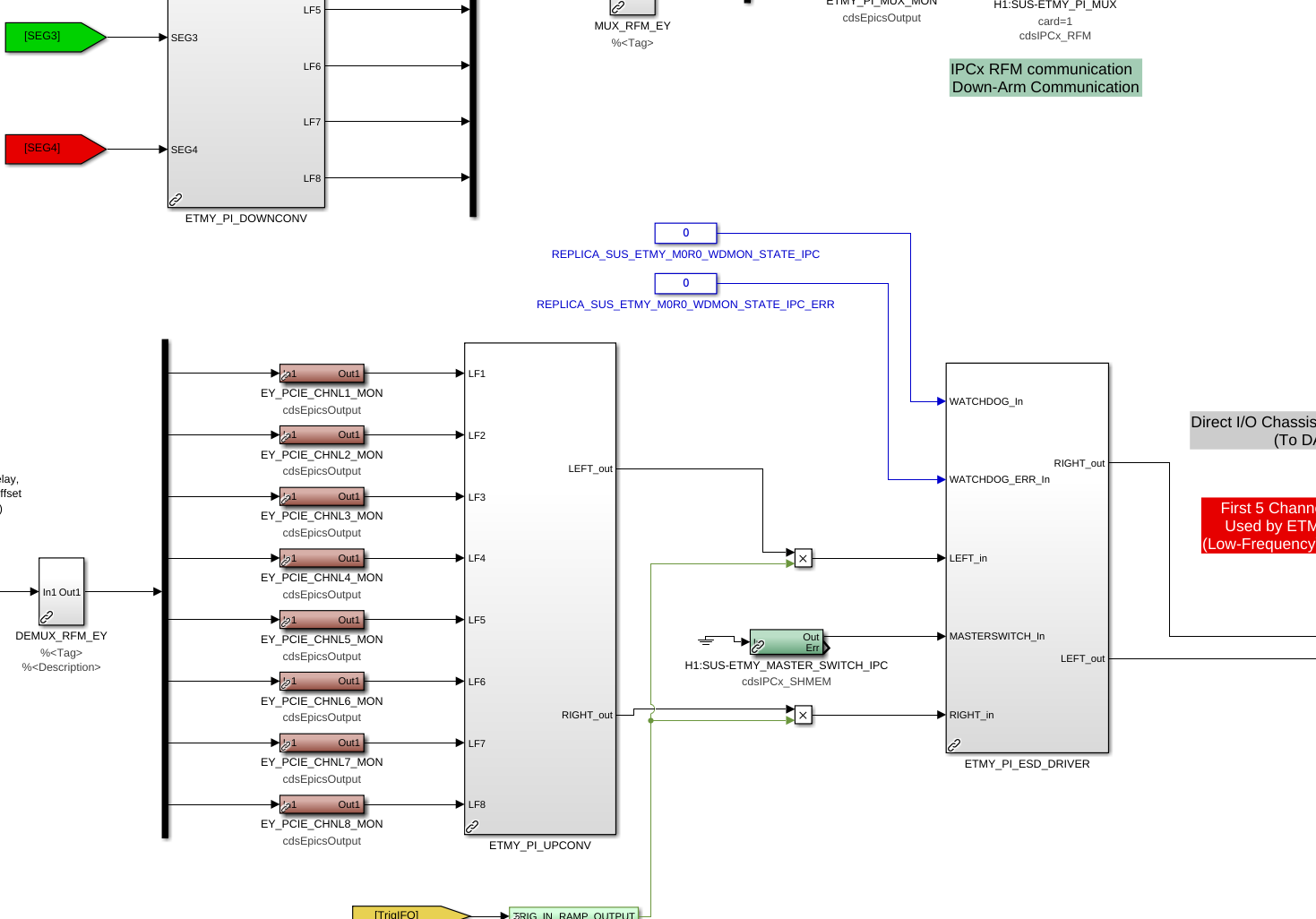
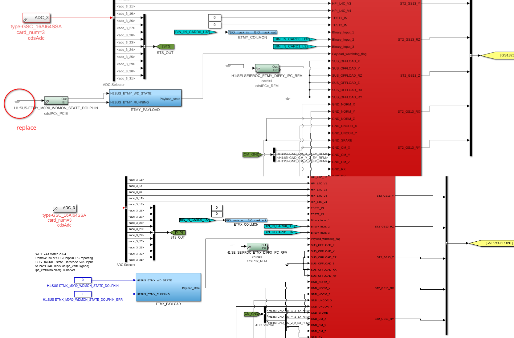
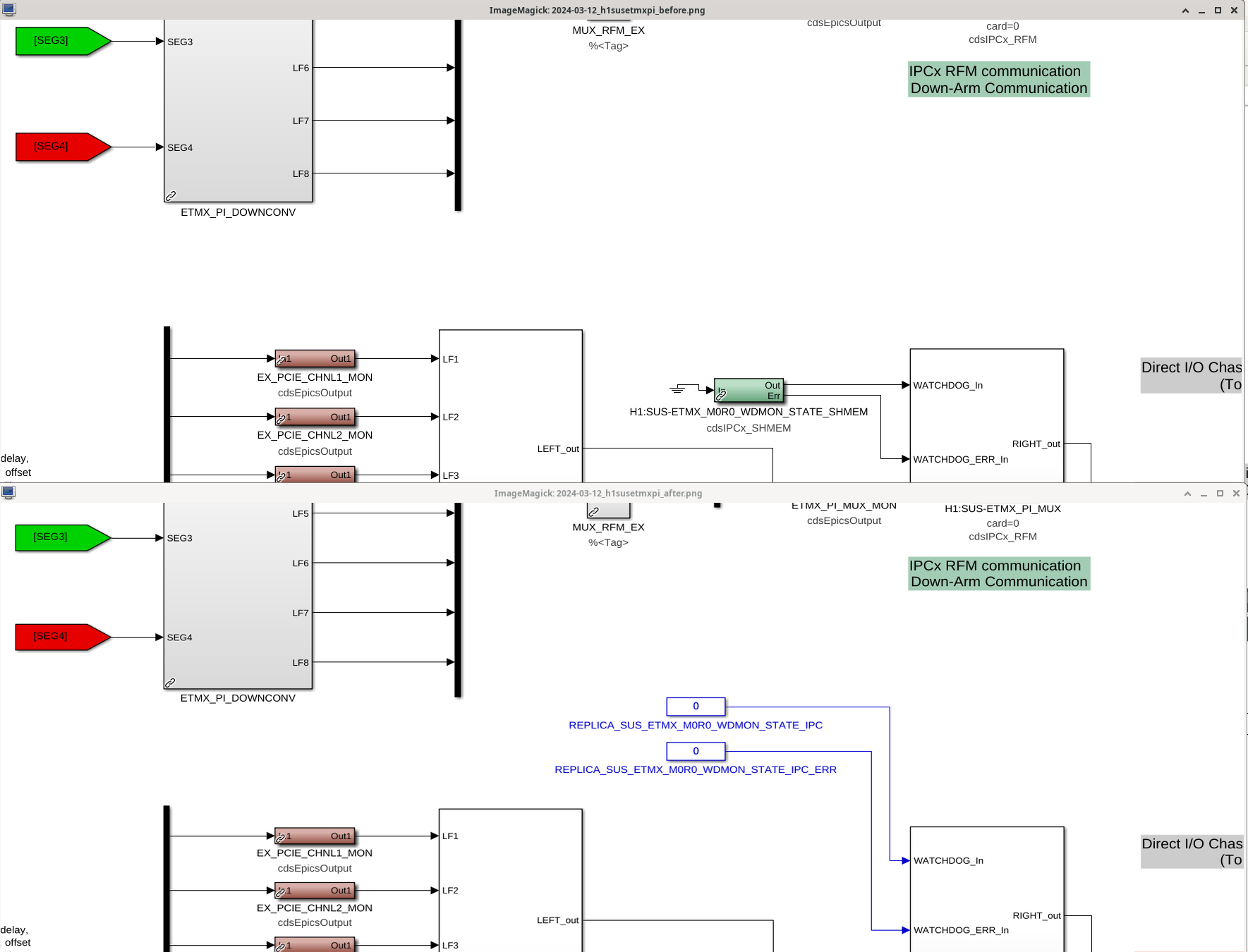
    - Found out during installation of these updated models that a WD value that we had removed in the individual models went out to the pi models. The sus pi models were updated to include constants as inputs in lieu of the removed WD values(attachment5)
ISI QUAD models (h1isietmx.mdl, h1isietmy.mdl):
    - Since the USER DACKILL connects to dolphin, we also changed the ISI QUAD inputs that feed into SUSWD_2_PAYLOAD from ground to both be 0 for WDMON_STATE_DOLPHIN and WDMON_STATE_DOLPHIN_ERR respectively(WDMON_STATE_DOLPHIN_ERR needs to be 1 because it later gets inverted)(attachment6)
Changes to medms (ETMs,TMSs adl files):
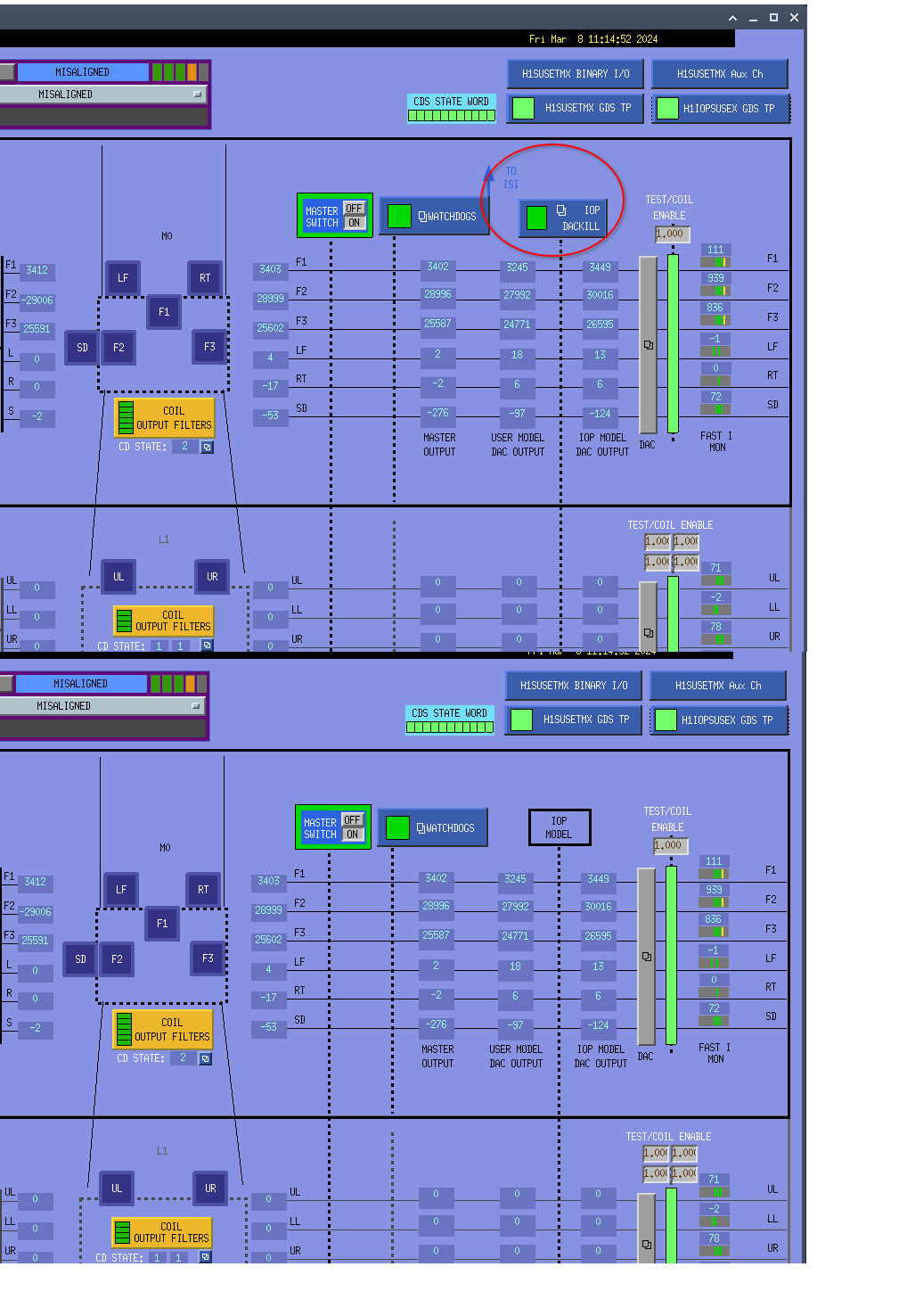
    - Removed the IOP DACKILL button on suspension medm and TO ISI arrow(attachment7)
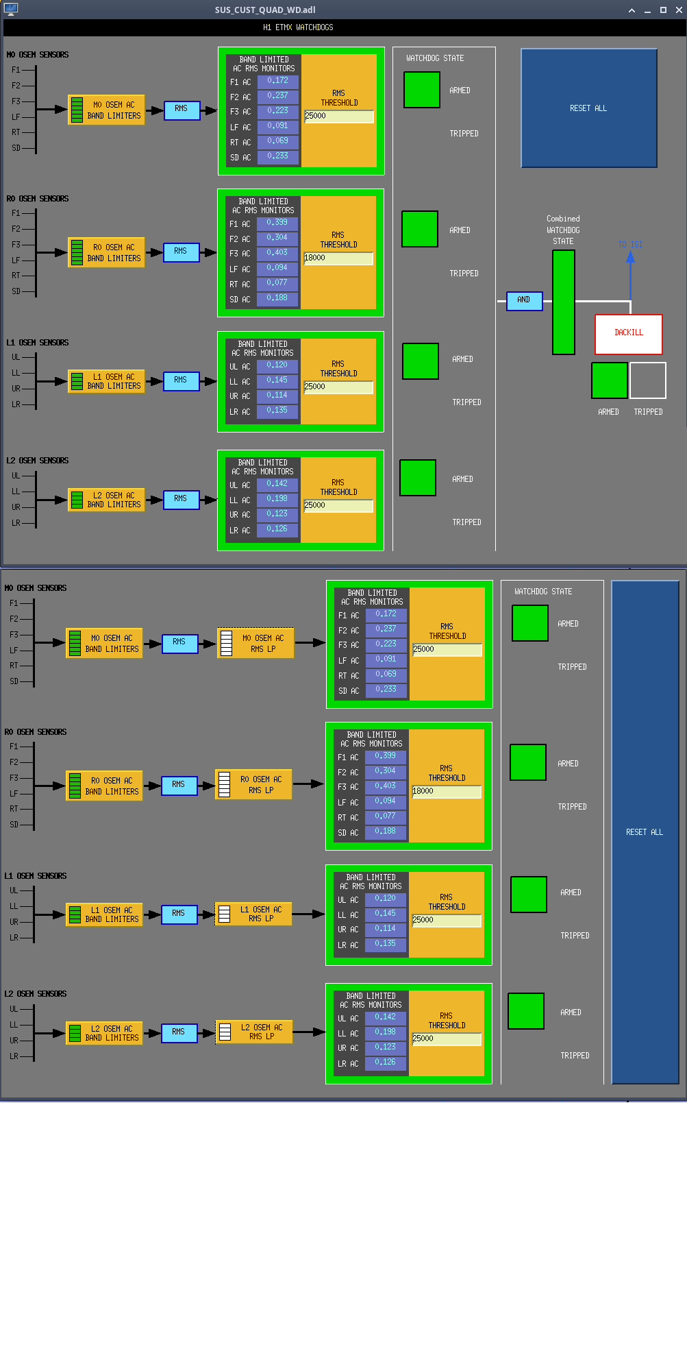
    - Inside the watchdog subscreens: added in the filter banks for the low pass and removed the diagrams showing the USER DACKILL logic(attachment8).
All changes have been committed to svn.

Images attached to this report
Comments related to this report
jeffrey.kissel@LIGO.ORG - 14:36, Wednesday 13 March 2024 (76350)CDS
Here's an updated version of Oli's 5th screenshot above, that shows the PI model changes to include a "before" screen shot which shows the SHMEM IPC that used to be there. Check the attachment in this aLOG.

P.S. I've now committed Dave's work on pi models to the userapps SVN, 
    /opt/rtcds/userapps/release/sus/h1/models/
        h1susetmxpi.mdl
        h1susetmypi.mdl
are both committed as of rev 27215.
Images attached to this comment
jeffrey.kissel@LIGO.ORG - 14:48, Wednesday 13 March 2024 (76351)
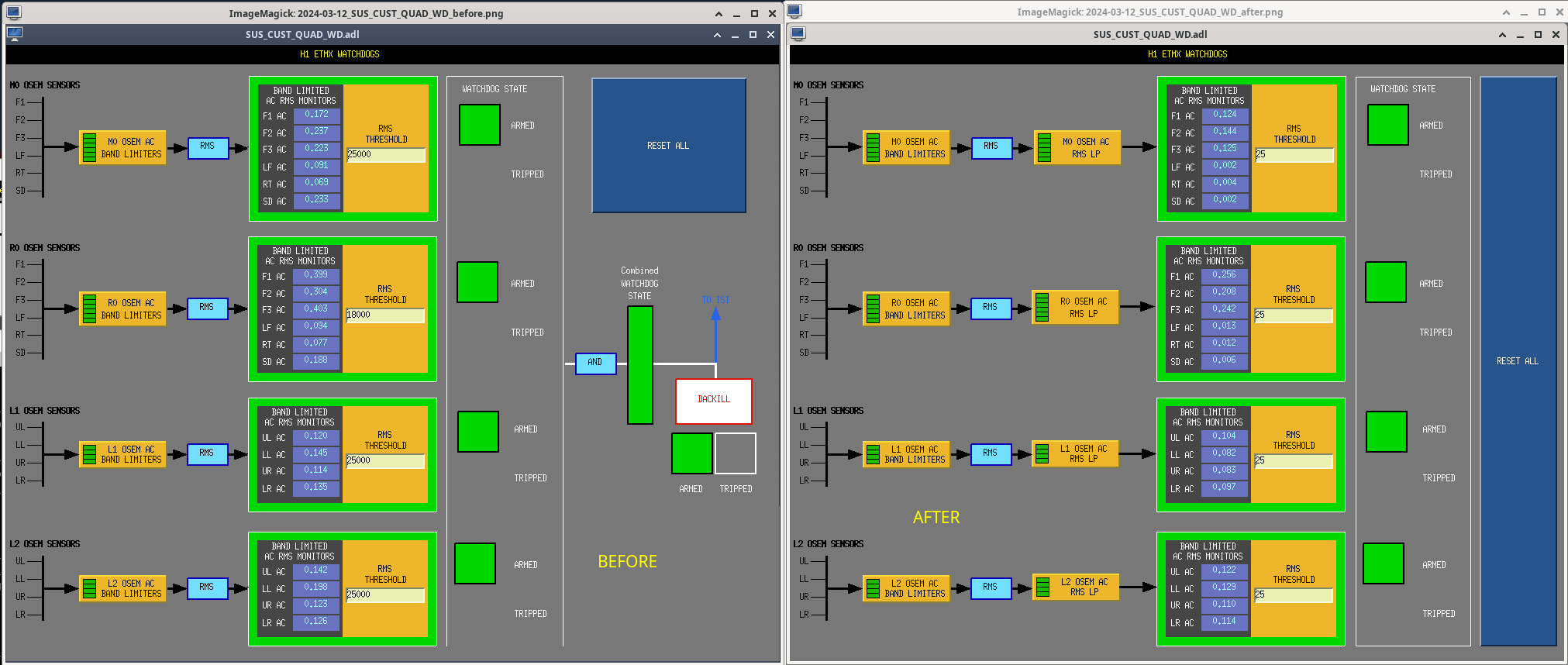
Oli's 8th screenshot showing the WD overview screen before vs. after shows the upgraded screen before the new channels existed and the infrastructure was filled out.

Here, I offer an updated "before vs. after" screenshot that shows an "after" with the way things should like when working normally now.

I've also committed the screen to the userapps SVN,
    /opt/rtcds/userapps/trunk/sus/common/medm/quad/
        SUS_CUST_QUAD_WD.adl 
committed as rev 27216.
Images attached to this comment
H1 AOS (CAL)
louis.dartez@LIGO.ORG - posted 23:51, Tuesday 12 March 2024 - last comment - 17:48, Friday 05 April 2024(76315)
Successful transition to new DARM offloading state + quiet-ish time
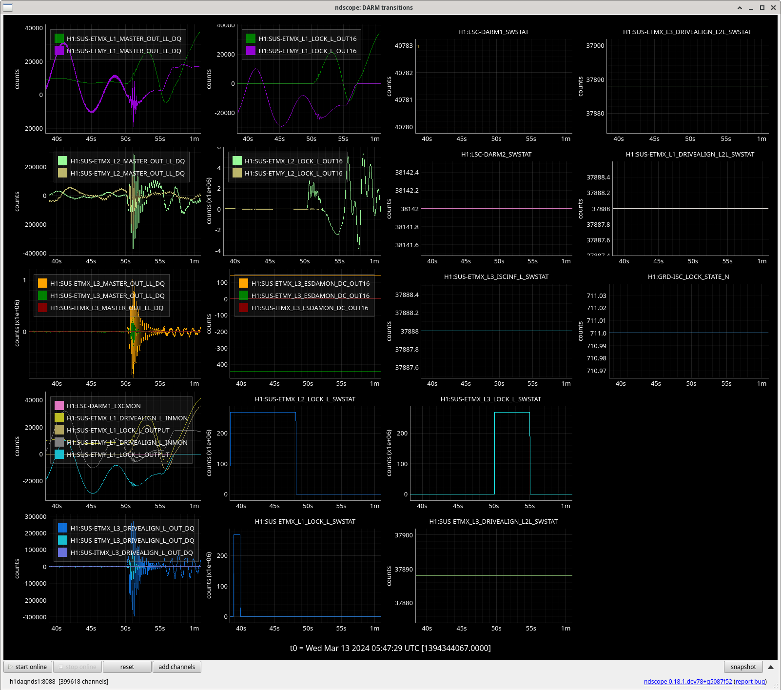
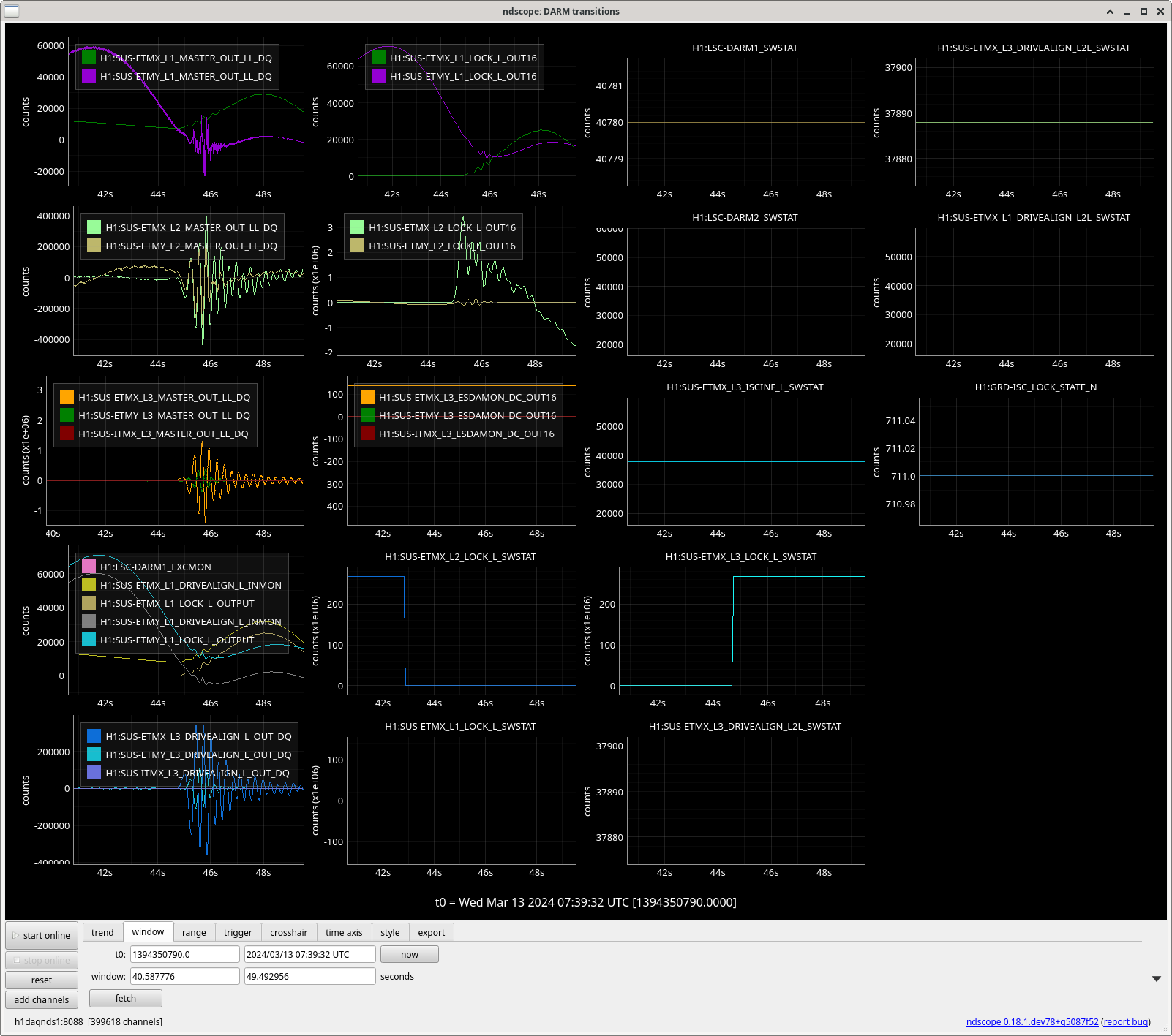
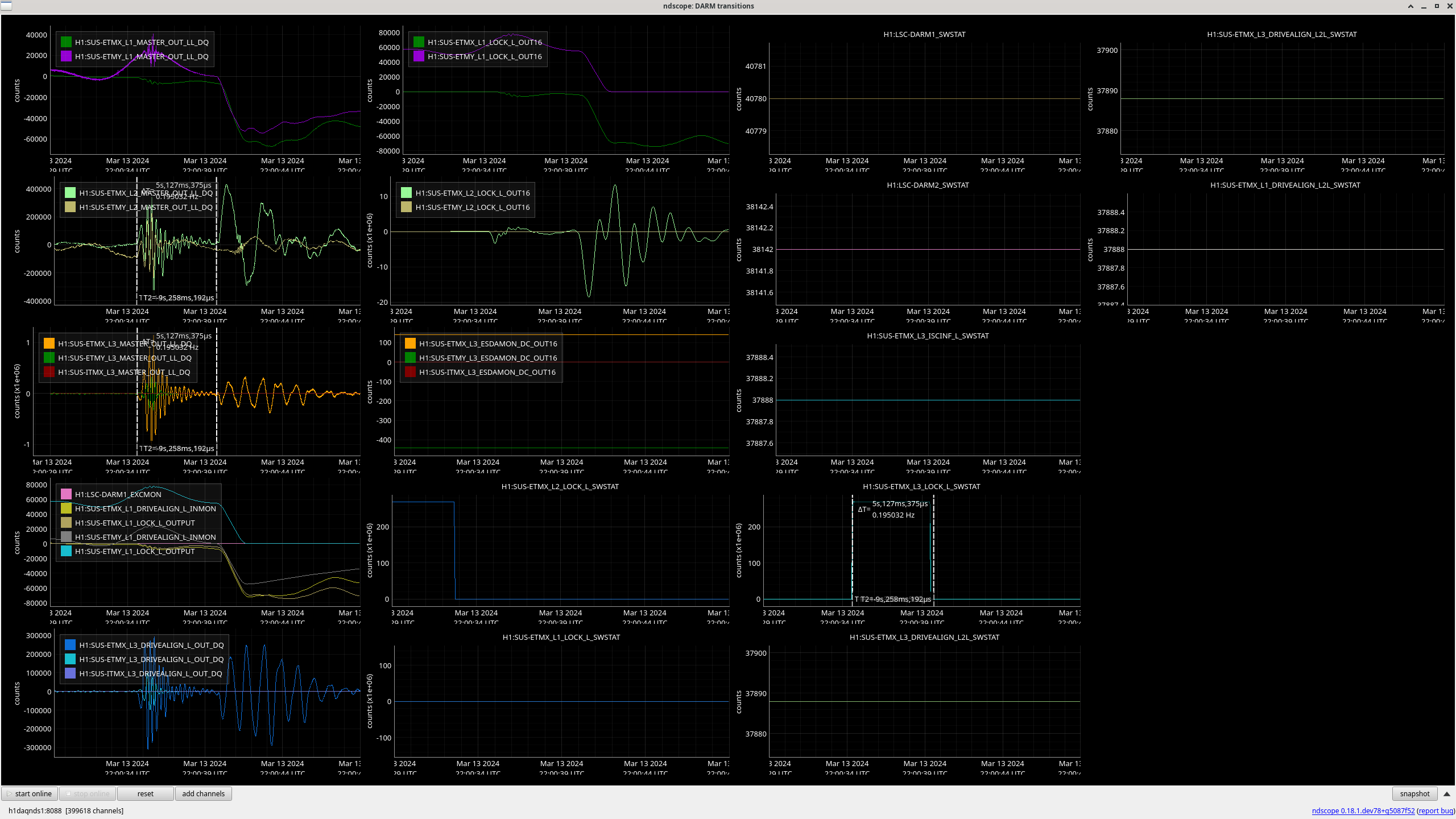
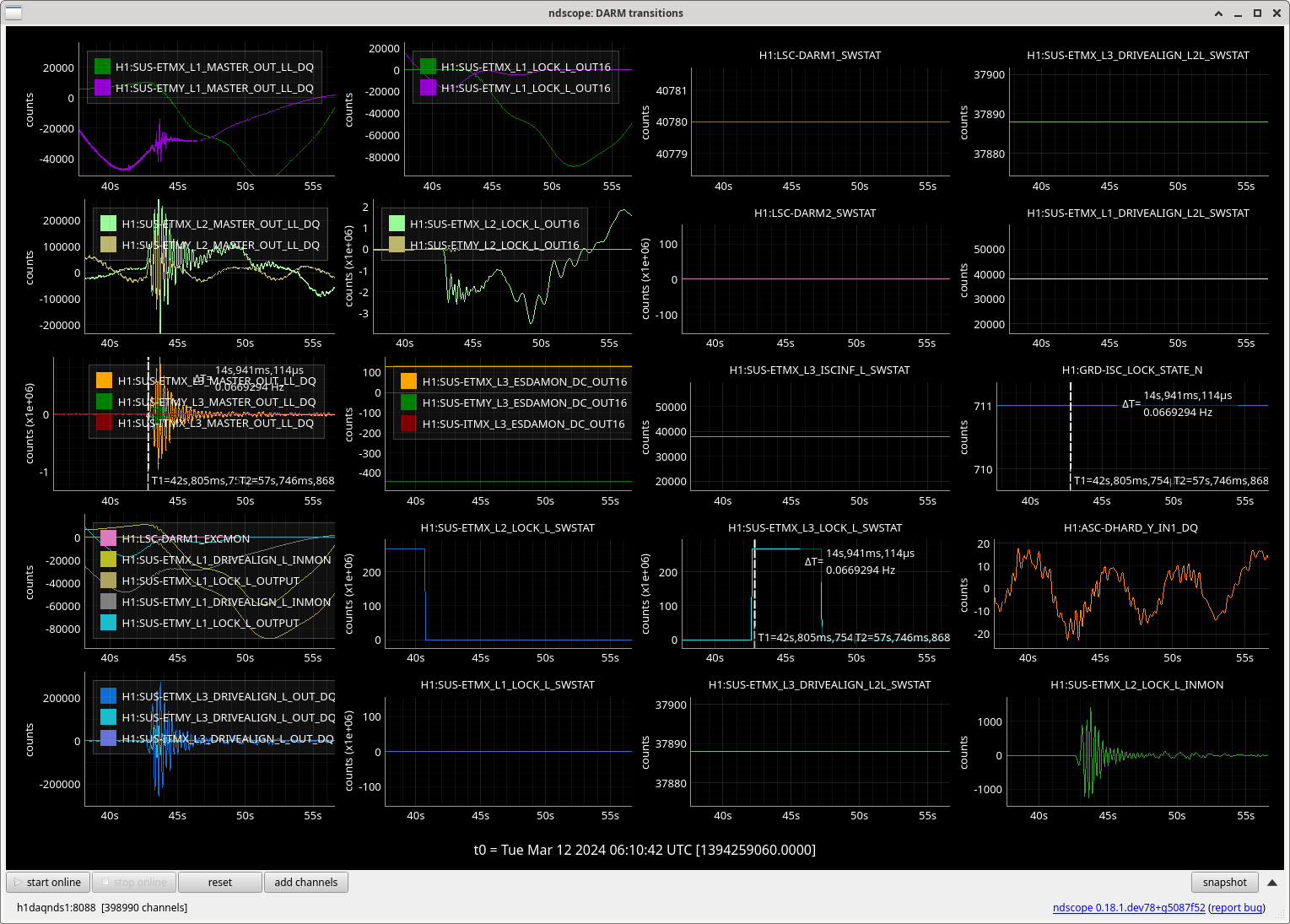
I was able to request and transition to the new DARM state without issue. ETMX still saw a pretty large kick. I'll have to circle back re: how large compared to previous attempts. We will also want to take a look at any effects moving the integrator on L2 LOCK L had.

Note: We do get a few SUS_PI warnings shortly after transitioning to this state.

Quiet time to monitor for non-stationarity:
Start GPS: 1394344327
Stop GPS: 1394346169

Turned off cal lines at GPS 1394346770.39

Elenna started a Bruco after the cal lines were turned off.  here is a screenshot of DARM in the new configuration. 20-90Hz looks high and below 15Hz looks low. It's hard to tell how much of this is real until CAL-CS is calibrated & that calibration is propagated to the DTT template.

I started an L2 LOCK IN1/IN2 injection using noise recorder at 1394347034.426. We used a tuned broadband measurement that Craig and I put together. Apparently it was too strong because we lost lock from this injection. It also tripped EX. I requested DOWN and the EX trip alarm reset. 
Images attached to this report
Comments related to this report
elenna.capote@LIGO.ORG - 23:53, Tuesday 12 March 2024 (76316)

Bruco is here: https://ldas-jobs.ligo-wa.caltech.edu/~elenna.capote/brucos/New_DARM/

Just from first glance looks like some residual LSC coherence, but not enough to explain the strange shape of New DARM.

craig.cahillane@LIGO.ORG - 11:29, Wednesday 13 March 2024 (76333)
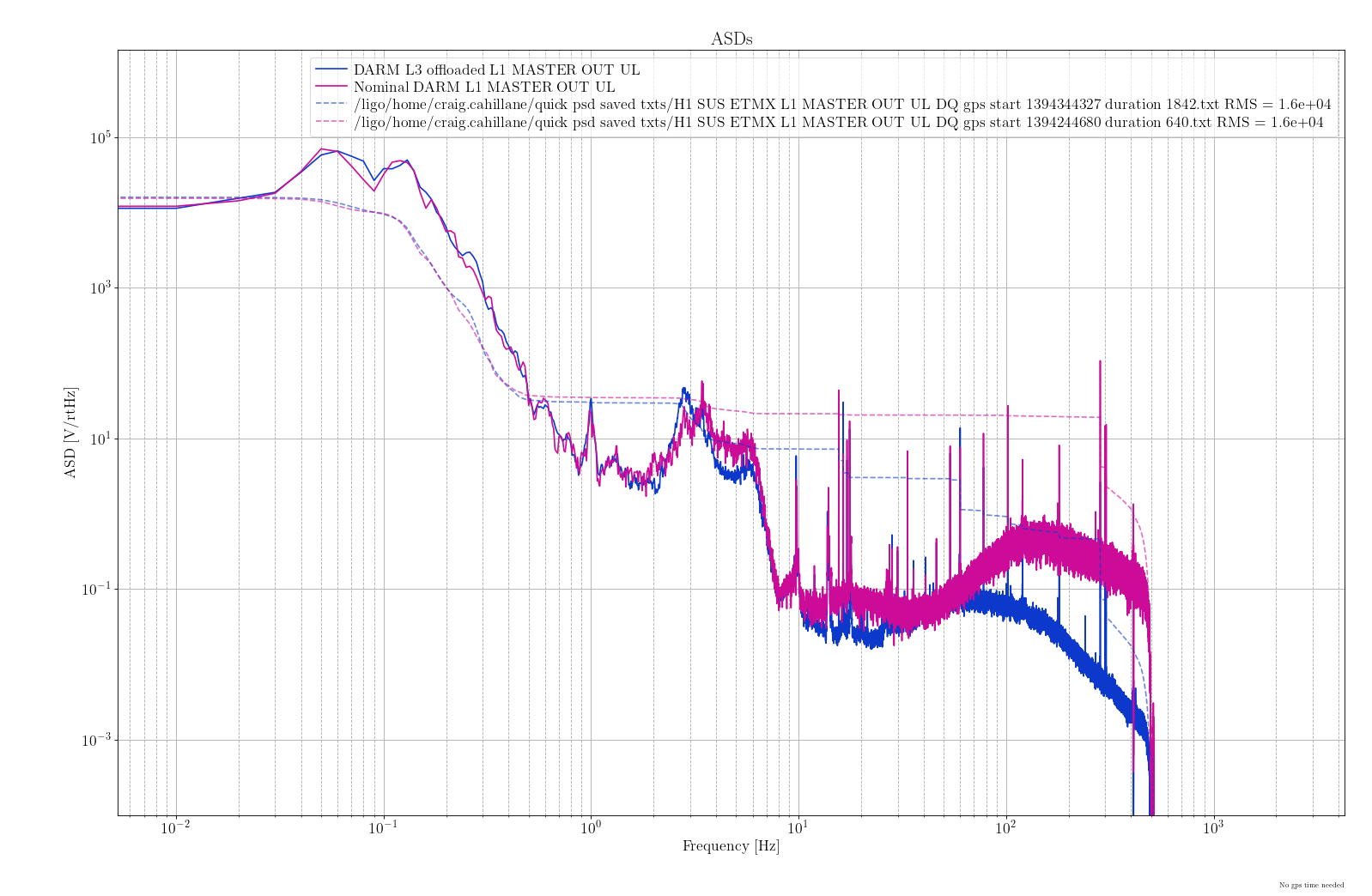
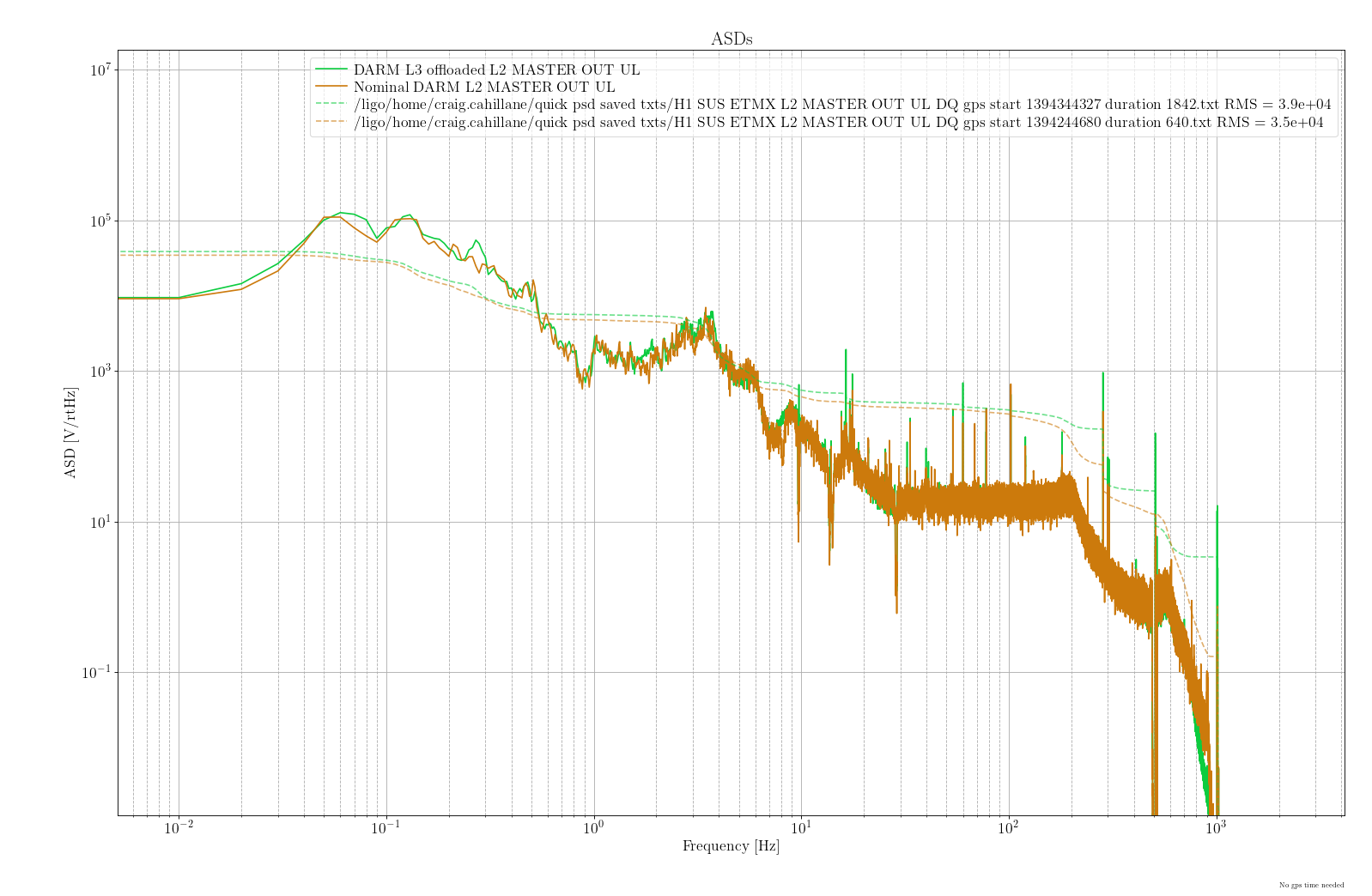
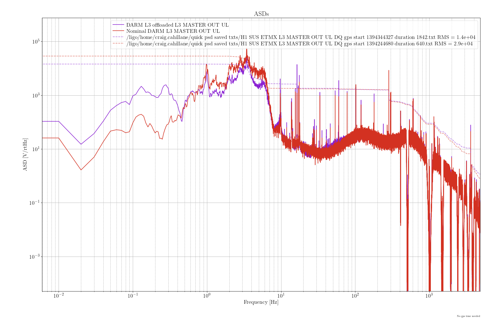
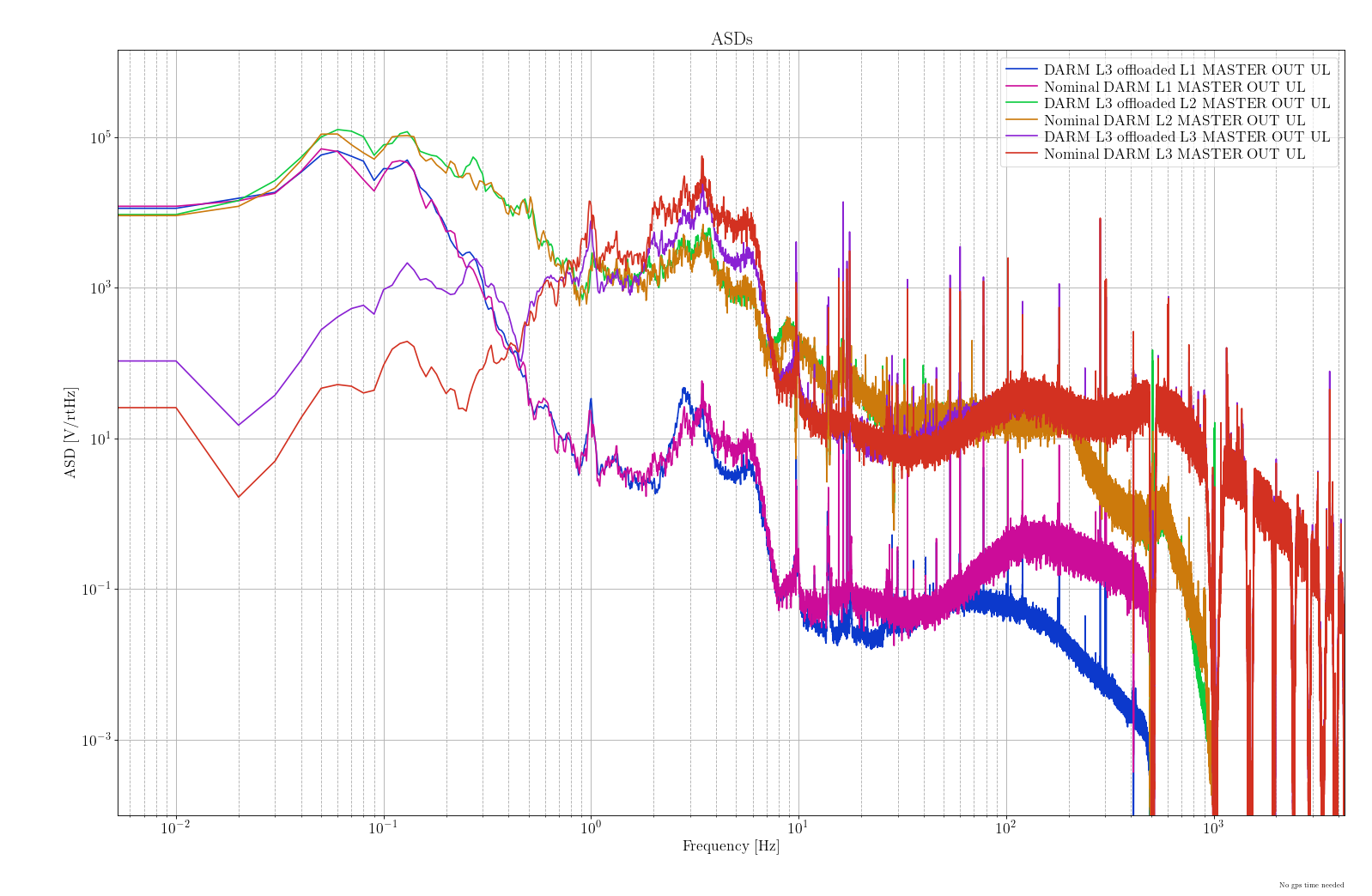
Here are plots comparing the MASTER OUTS on ETMX during Louis's quiet time here with L3 offloaded, vs Gabriele's quiet time in alog 76278 during Nominal DARM.

We are concerned only with the filter changes that Louis and Sheila made to offload more of L3's length actuation onto L2.  
Because L2 is used to control both length and angular degrees of freedom, it can be easy to ask too much of L2. 
This lock seems to indicate that this configuration is fairly stable.

I looked at the UL MASTER OUTs for the L1, L2, L3 on ETMX.
1) RMS on L3 drives is halved.  There is much less L3 drive from 1 to 6 Hz, which dominates the RMS.  
2) L2 drives are largely unchanged.  
3) L1 drives are changed, but the RMS remains similar.  There is much less HF content in the L1 drive with L3 offloaded, and the shape of the resonances around 3 and 6 Hz is altered.

Overall it's hard to tell which stage is picking up L3's slack from these PSDs.  I believe the intention was to offload to L2, but we don't see any obvious change in what control signal is being sent to the L2 stage.  This could simply mean that the angular controls are relatively stronger in the L2 controllers.  We'll look at the DRIVEALIGN signals to try and figure that one out quantitatively. 
Images attached to this comment
gabriele.vajente@LIGO.ORG - 12:29, Wednesday 13 March 2024 (76341)

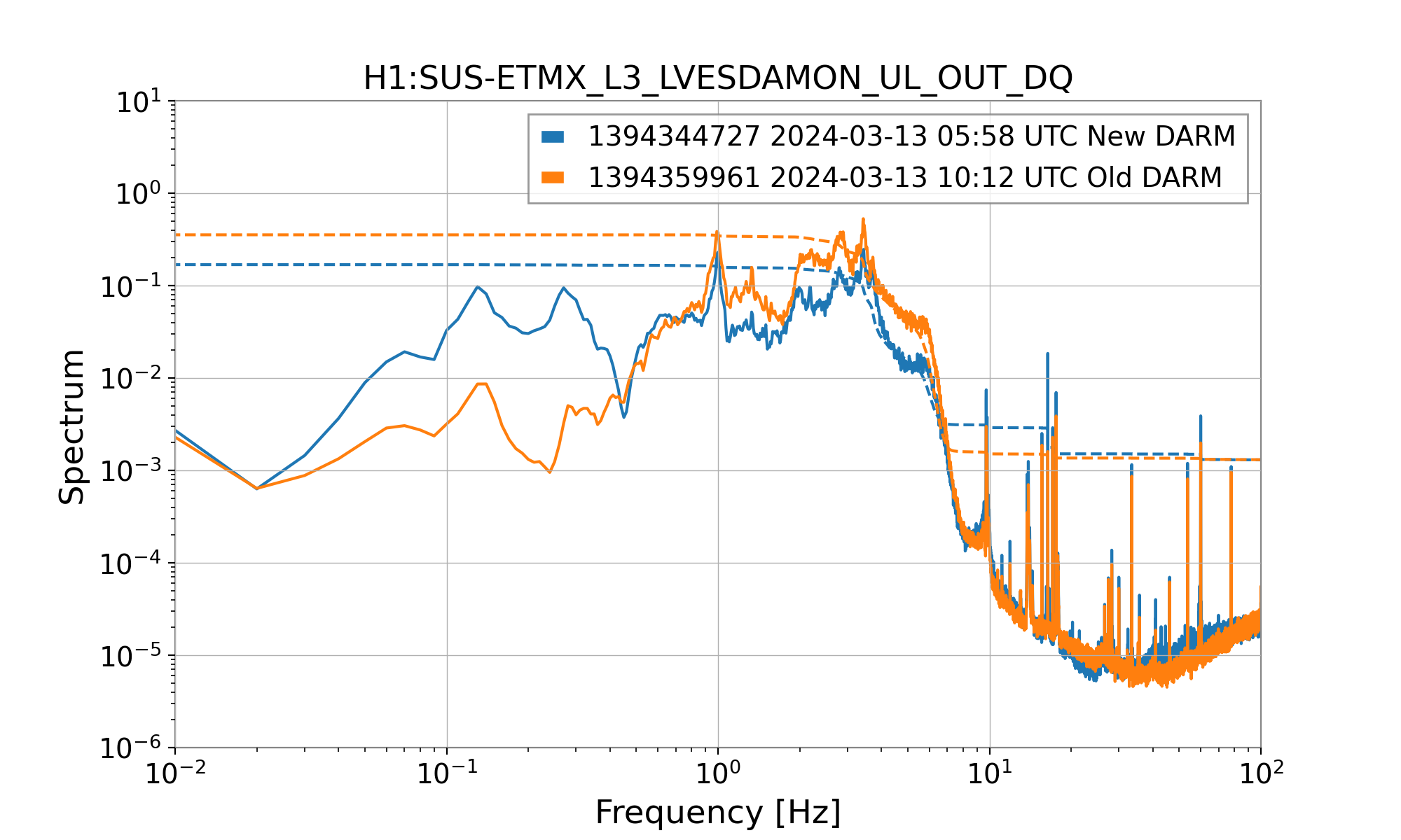
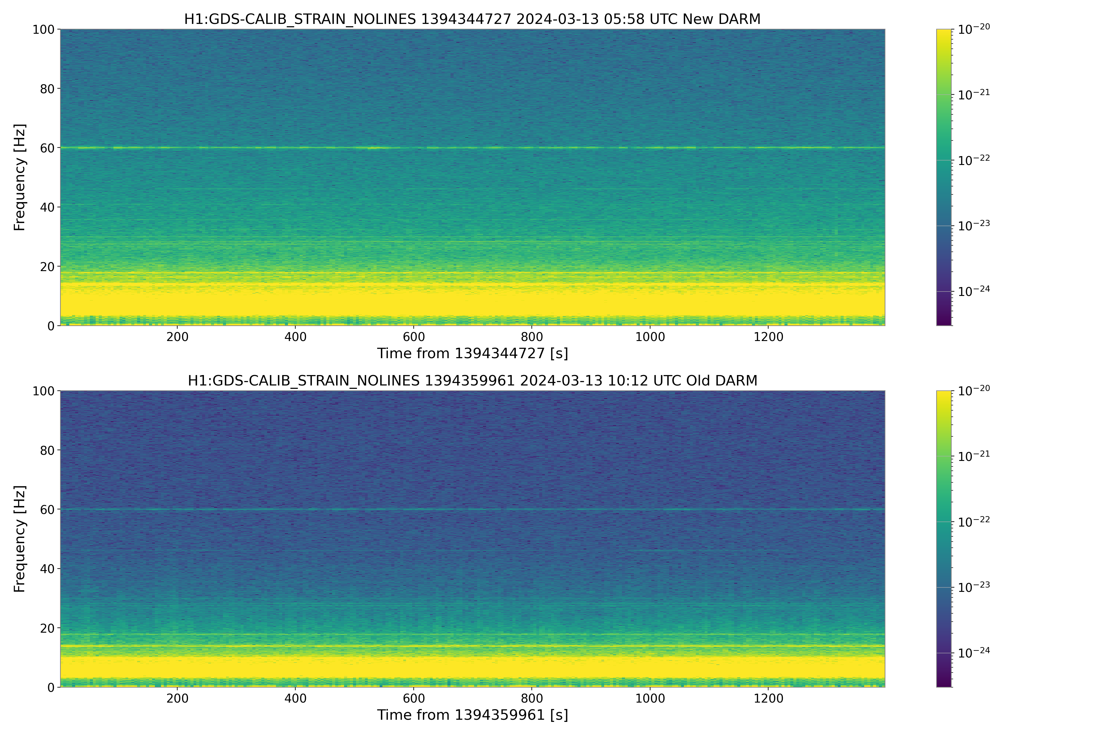
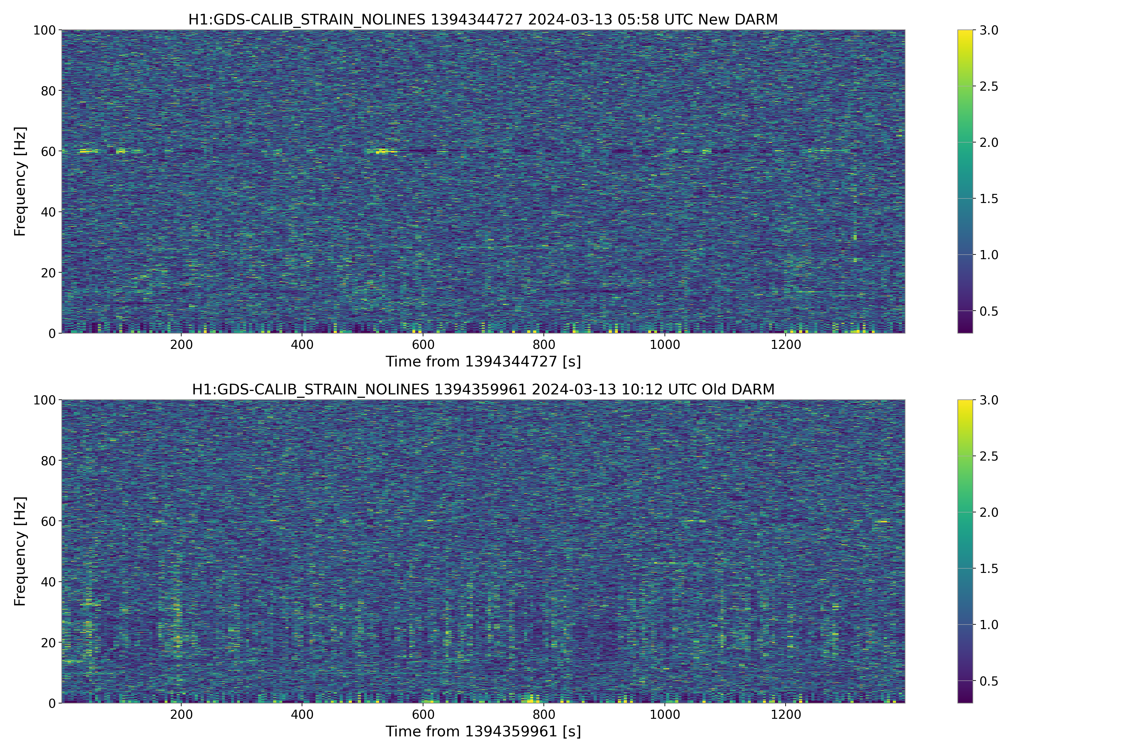
The new DARM loop configuration reduces the DARM noise non-stationary at low frequency.

First plot compares the ESD drive with the Old DARM and the New DARM, confirming that the RMS is significantly reduced, especially at the relevant frequencies.

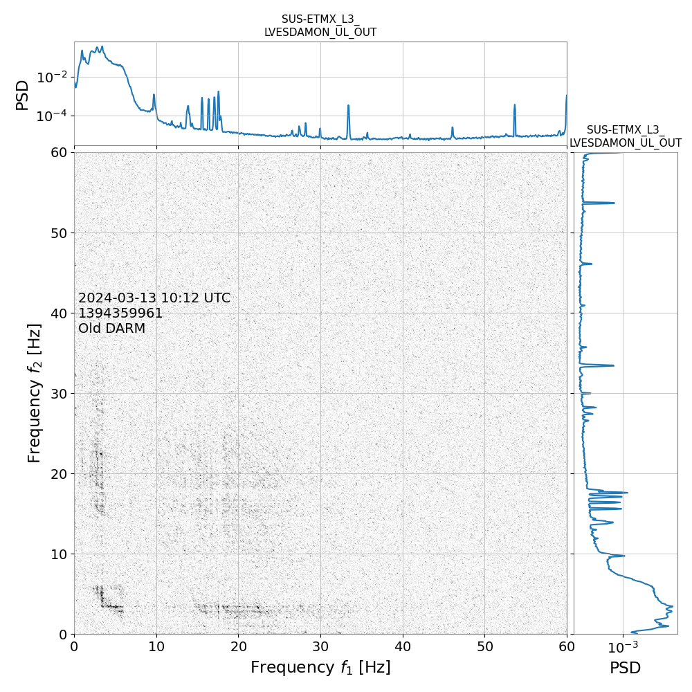
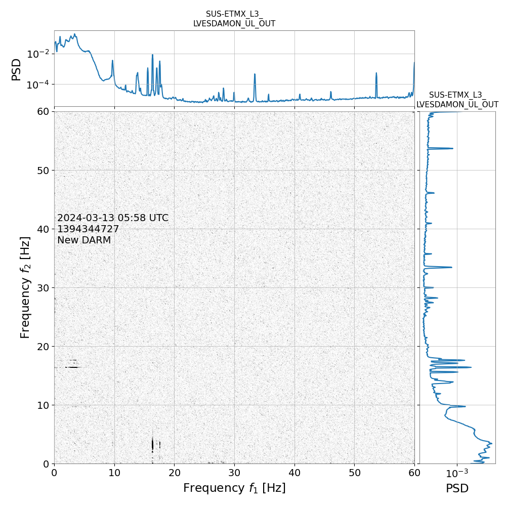
Second and third plots are spectrograms and whitened spectrograms of GDS-CALIB_STRAIN in the two configuration. Despire GDS-CALIB_STRAIN being wrongly calibrated with the New DARM, it is clear that the low frequency non stationarity is gone in New DARM.

Last two plots are the bicoherence of DARM with the ESD drives, showing that in the Old DARM there is still some bicoherence for noise in the 10-30 Hz region, while in the New DARM this is gone.


Images attached to this comment
sheila.dwyer@LIGO.ORG - 15:23, Wednesday 13 March 2024 (76344)

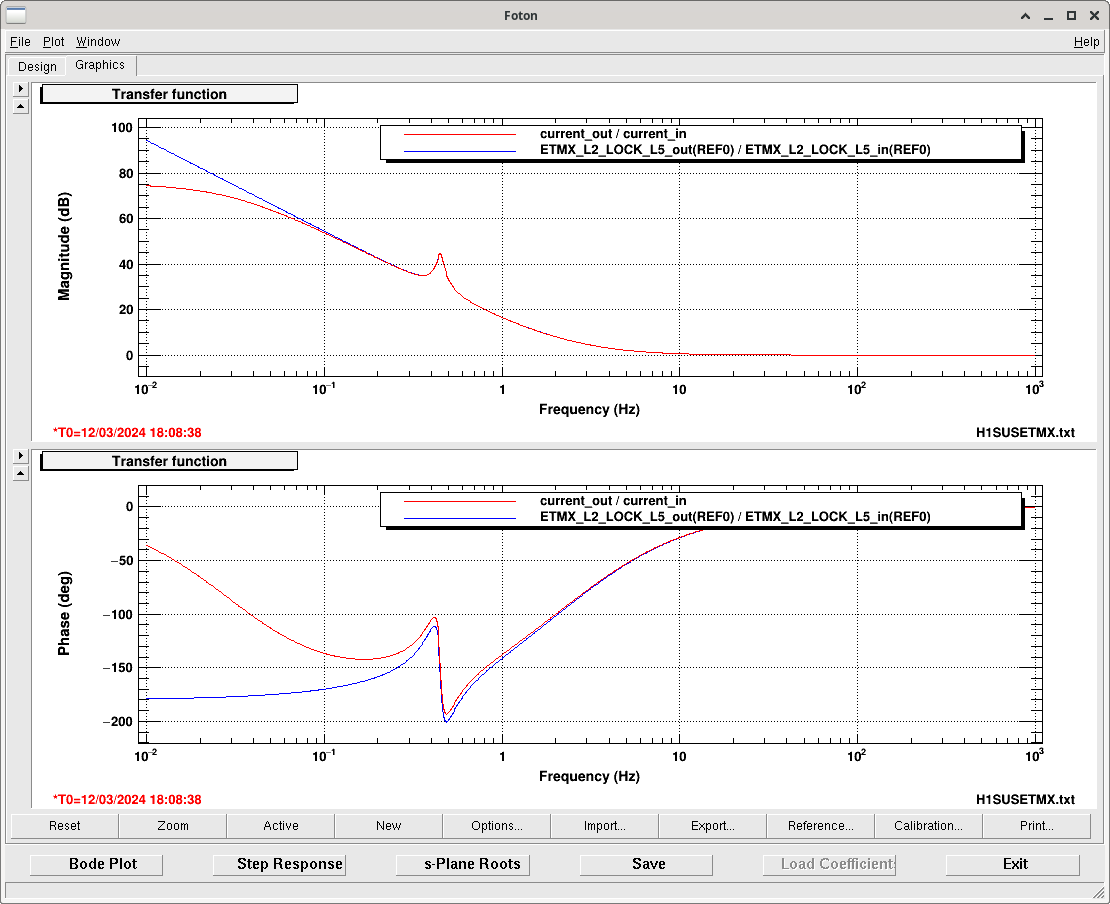
These transitions last night were made with a different L2 LOCK filter (which is in L2 LOCK L FM6, replacing the filter used in earlier new DARM configurations that was at FM2).  The attached screenshot shows the filter change, I replaced the poles at zero with poles at 0.03 Hz to get rid of the integrator here without changing the phase at the crossover much. This was done with the guardian version 27211

Plots of the actuators during the transitions are attached, here and here,  they can be compared to the one that Louis posted where we used L2 LOCK FM2.   This suggests that the change to these poles didn't help to reduce the transient during the transition. 

Today we tried another change to the transition, this time Evan and I moved the poles in L2 LOCK L from 0.03 Hz to 0.1 Hz, and changed the ramp time for the transition to 10 seconds (from 5).  The model is shown in the attached PDF where the new filter is in place in the transition traces.  This transition wasn't smoother than the others, see here

Images attached to this comment
Non-image files attached to this comment
evan.hall@LIGO.ORG - 15:30, Wednesday 13 March 2024 (76355)CAL, ISC

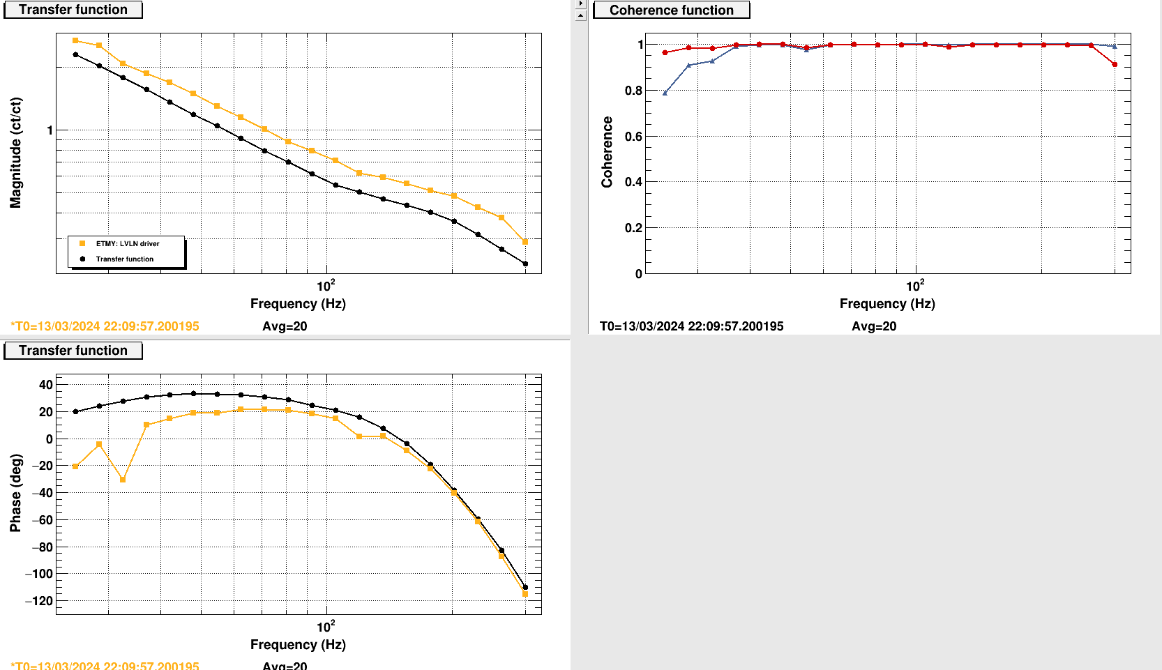
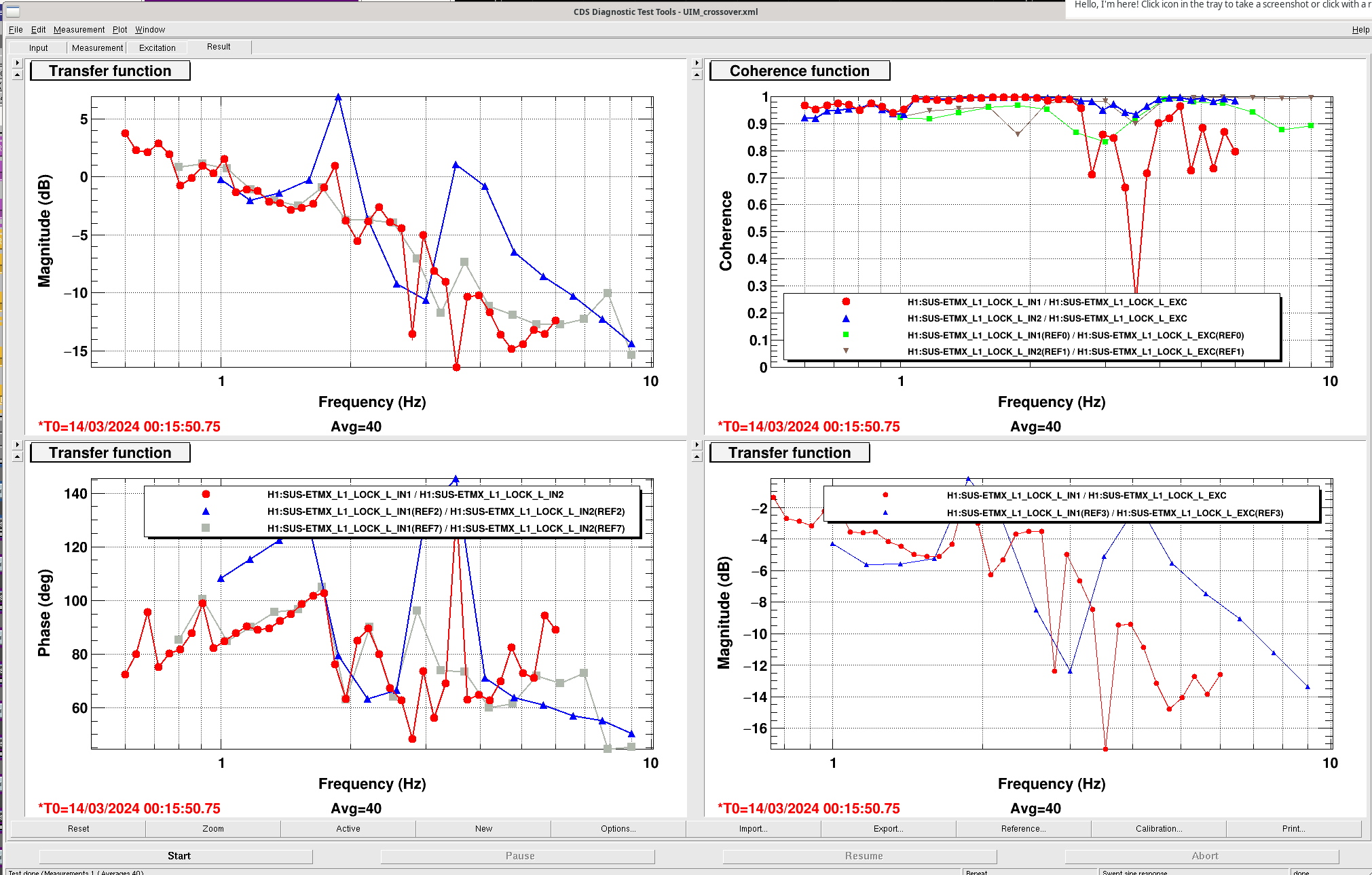
The new UGF is 70 Hz with 20° of phase margin. The crossover between L2 and L3 is at 18 Hz with probably about 40° of phase margin (low coherence due to interference with calibration lines). We have not measured the L1 to L2 crossover yet.

Images attached to this comment
Non-image files attached to this comment
louis.dartez@LIGO.ORG - 19:36, Wednesday 13 March 2024 (76365)
S. Dwyer, E. Capote, E. Hall, S. Pandey, L. Dartez


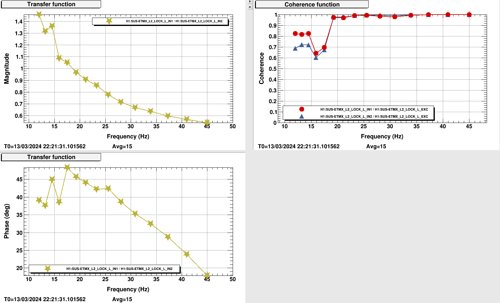
Here are some notes from our efforts to measure IN1/IN2 at the L1 LOCK L input.

- Sheila adjusted UIM measurement template for new darm config. This template is at /opt/rtcds/userapps/release/lsc/h1/templates/DARM/UIM_crossover.xml.
- Evan ran the template initially and saw that the UGF is near 1Hz. He adjusted the excitation amplitude along the way to improve coherence for the next time we run this measurement.
- Evan added a high pass filter in the L3 DRIVEALIGN bank with a cutoff frequency at at 5Hz
  - first filter attempt was at 8Hz; possibly caused a roll mode to excite near 13.75Hz
  - second filter attempt was at 5Hz; this seemed to improve the roll mode excitation

We ended up losing lock a shortly after the injection finished due to PRC activity.
Images attached to this comment
Non-image files attached to this comment
evan.hall@LIGO.ORG - 17:48, Friday 05 April 2024 (76995)

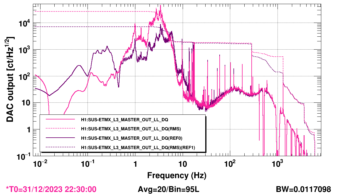
Comparison of DARM ESD drive from end of O4a versus a few days ago. The microseism was about 0.2 µm/s in both cases. The rms DAC drive from 0.1 Hz to 0.3 Hz is about 400 ct, so even in cases of exceptionally high microseism it will be subdominant to the 7000 ct rms that is accumulated above 1 Hz.

Images attached to this comment
H1 PSL
sheila.dwyer@LIGO.ORG - posted 15:21, Tuesday 12 March 2024 - last comment - 15:33, Wednesday 13 March 2024(76303)
attempt to pico ISS second loop, undid changes

Sheila, Camilla, Jennie W, Keita remote

Stefan and Daniel suspect that our excess noise around 100 Hz might be due to intensity noise, and we did have a large shift in alignment of the beam transmitted through IM4 (76291) 76241.  I moved pico 1, first to center the beam on the ISS QPD, which made the power on the ISS array PDs drop, and didn't improve the spectrum of the ISS Sum inner or outer channels (we did this with the loop open).  We reverted this, then looked at the QPD position in O4a when we had 60W input power, went to 60W input power and pico'd to bring the beam to the same location as O4a.  This also didn't improve the spectrum, so we brought the pico back to where we started.

Images attached to this report
Comments related to this report
jennifer.wright@LIGO.ORG - 16:13, Tuesday 12 March 2024 (76306)

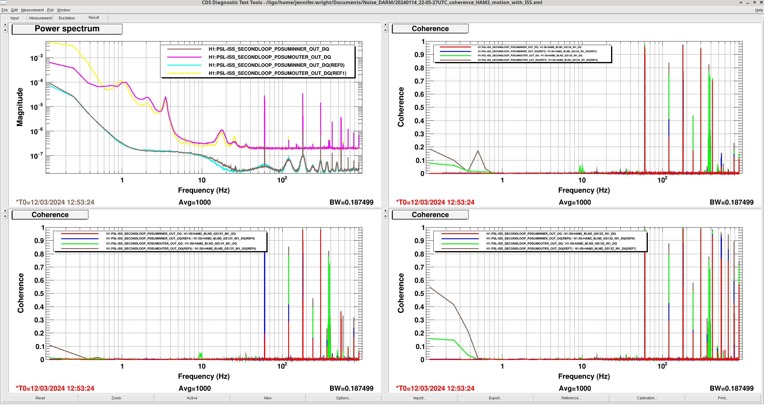
Sheila asked me to compare the ISS second loop outputs with from our recent NLN lock last night to that during O4a. The spectra doesn't show much difference in the noise (top left plot shows Jan 14th lock in cyan and yellow, last night's one in pink and brown).

The other three plots shows the coherence of ISS output with all three GS13s on the HAM2 optical table. There only seems to be coherence at the power lines.

So maybe the ISS is not causing intensity noise to couple into DARM differently pre and post vent.

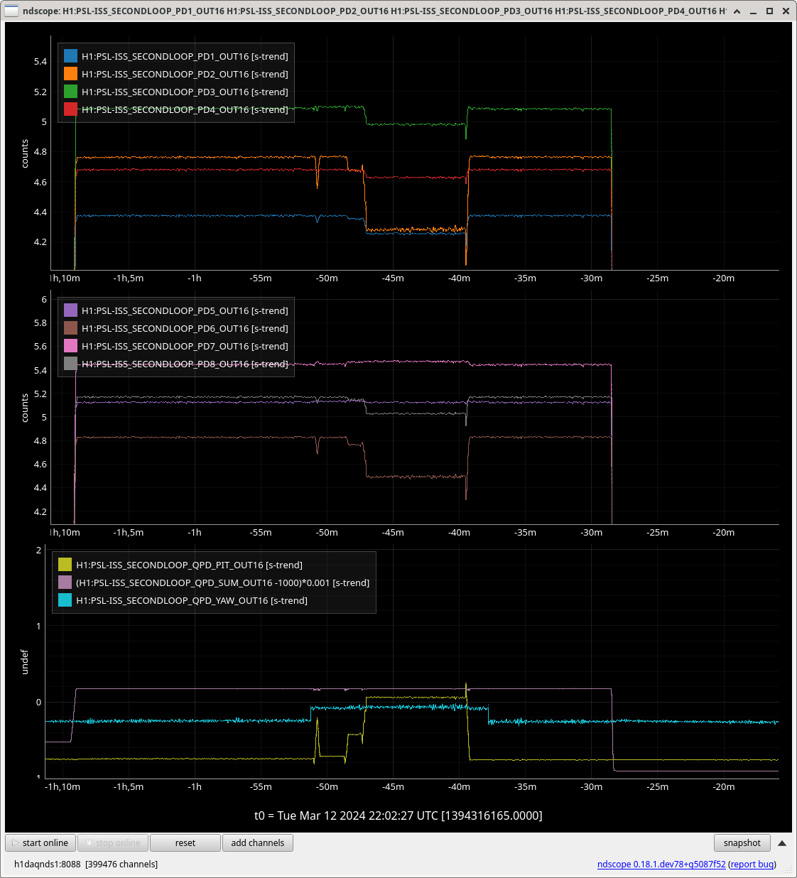
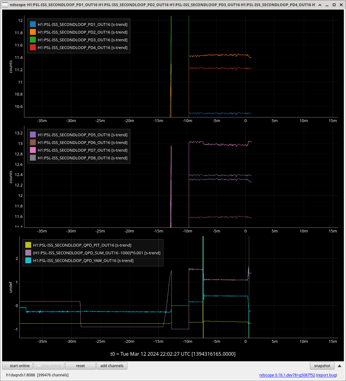
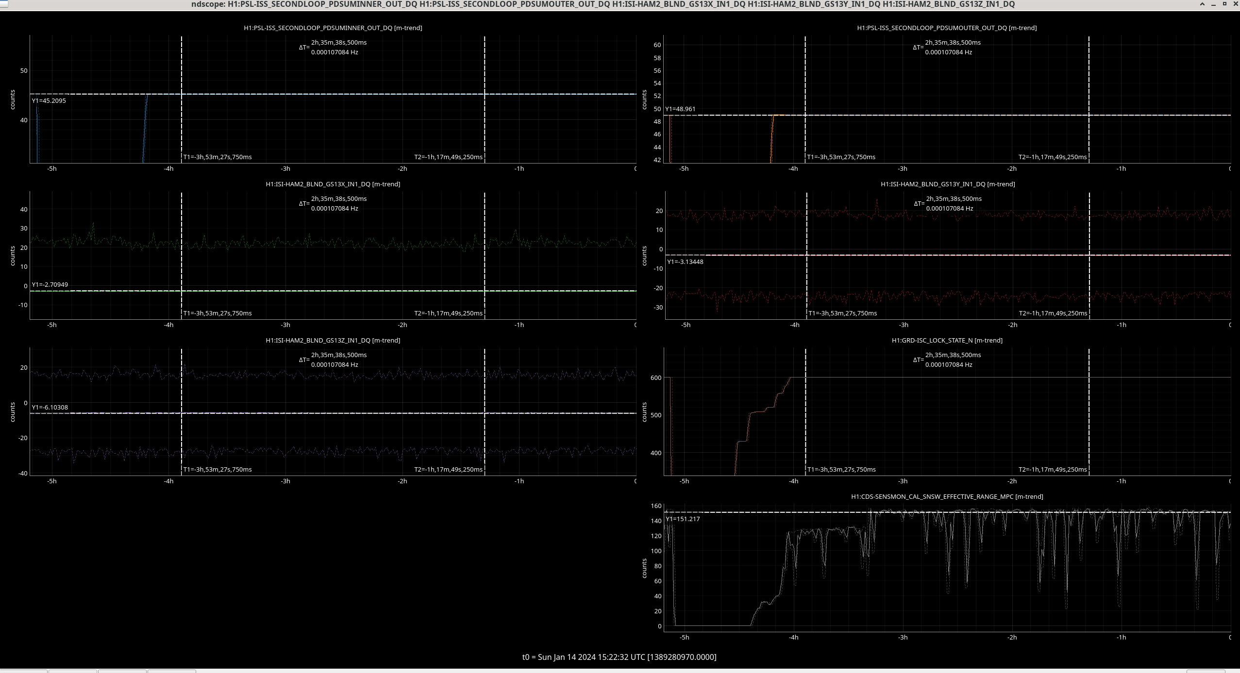
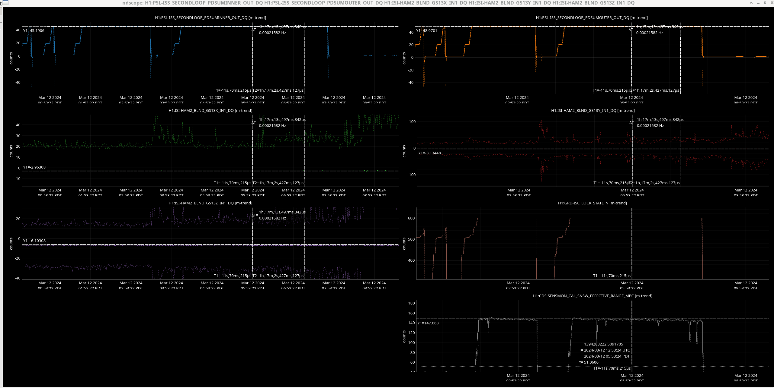
Images 2 and 3 attached shows the ndscope fro all channels I used around the two times I took spectra.

Time 1 = 2024-01-14 22:05:27 UTC

Time 2 = 2024-03-12 12:53:24 UTC

Channels for ISS:

H1:PSL-ISS_SECONDLOOP_PDSUMINNER_OUT_DQ

H1:PSL-ISS_SECONDLOOP_PDSUMOUTER_OUT_DQ

Channels for GS13s:

H1:ISI-HAM2_BLND_GS13X_IN1_DQ

H1:ISI-HAM2_BLND_GS13Y_IN1_DQ

H1:ISI-HAM2_BLND_GS13Z_IN1_DQ

Images attached to this comment
camilla.compton@LIGO.ORG - 15:33, Wednesday 13 March 2024 (76356)

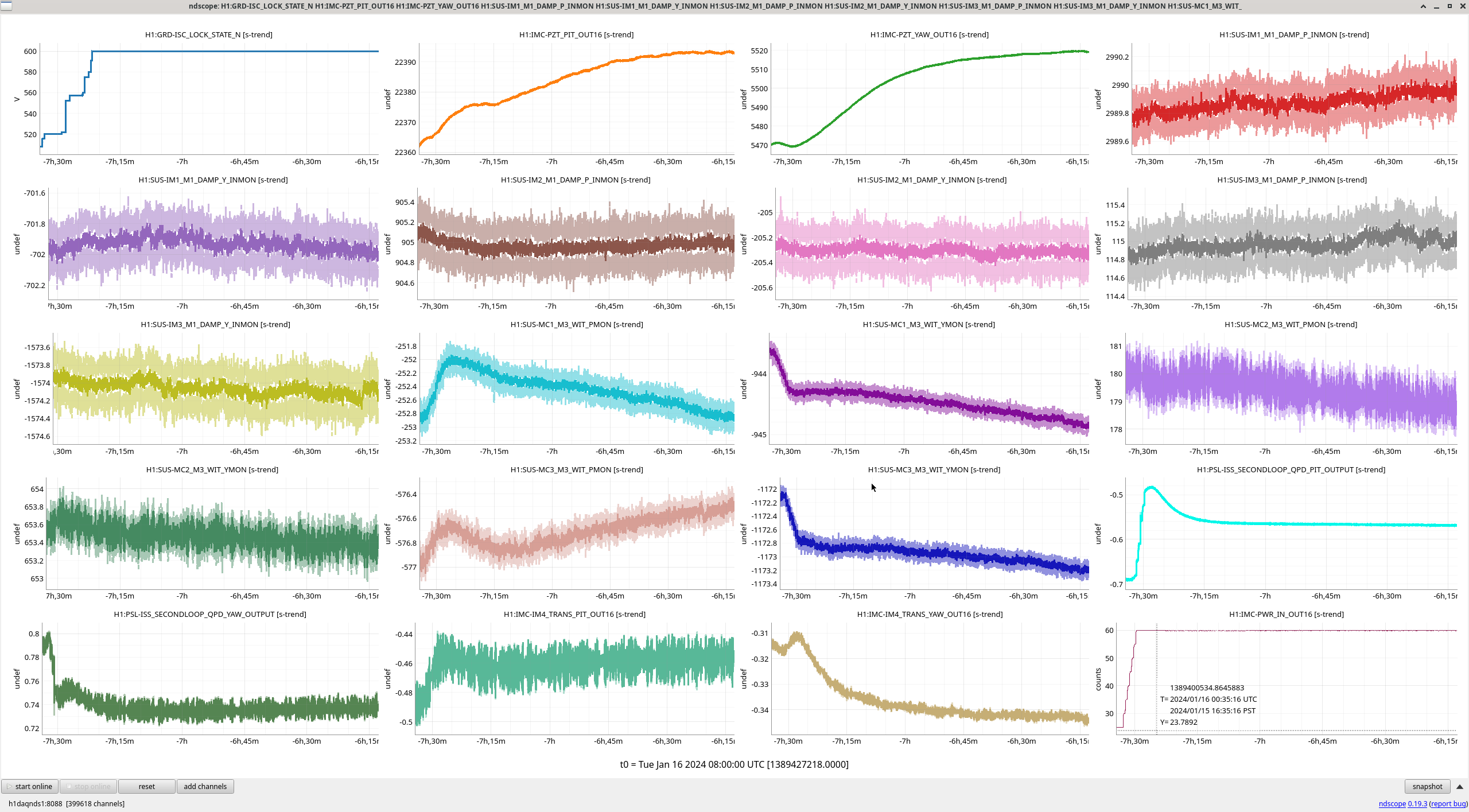
I looked at the pointing of the IMs and MCs from the start of a lock 16th Janary to now. As previously found, nothing seems to have changed much, IM1 P changed by ~100 counts, more than the other IMs, but it's unclear what these counts are calibrated to.

Images attached to this comment
H1 SQZ
naoki.aritomi@LIGO.ORG - posted 21:28, Friday 08 March 2024 - last comment - 09:33, Thursday 14 March 2024(76226)
4.5dB squeezing in IFO with 40 times more CLF power

Naoki, Vicky, Nutsinee, Matt

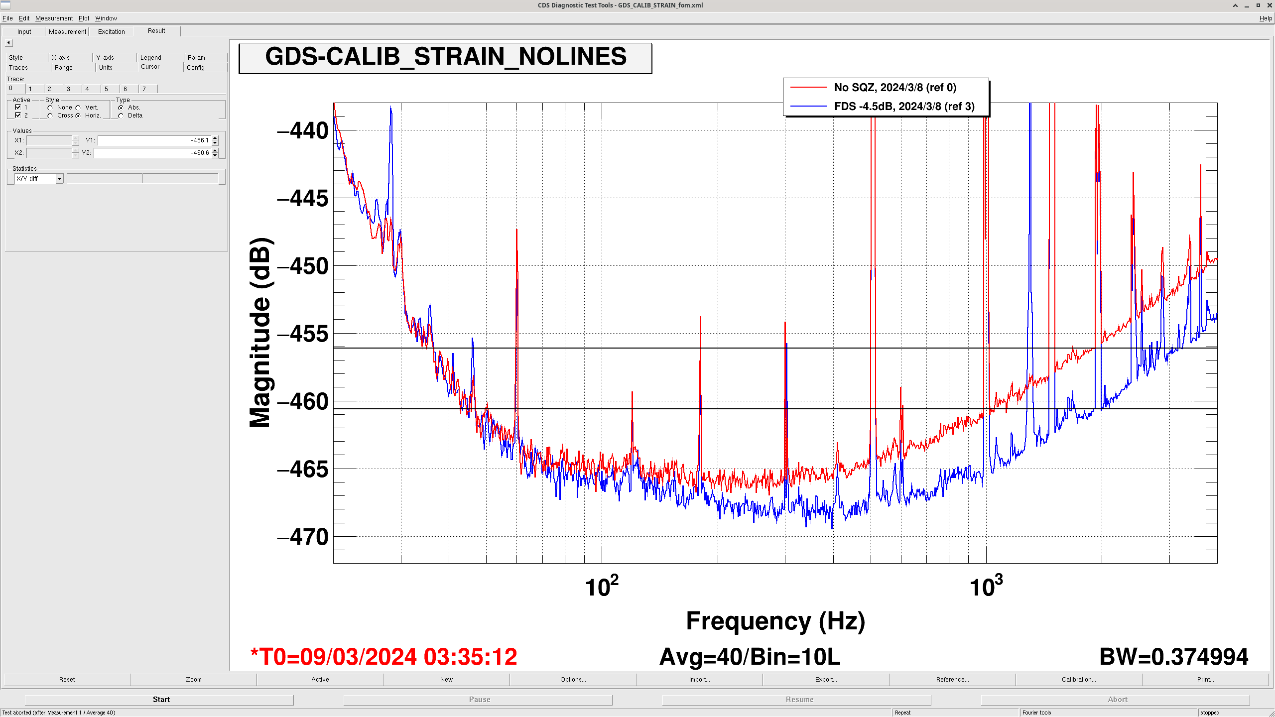
We recovered the FDS and got 4.5dB squeezing in IFO with 40 times more CLF power as shown in the attached figure. 

First we restored the ZM1/2/3 and FC1/2 OSEM positions to the values in O4a. Then we found the FC green trans in camera and PD. We aligned FC1 and FC2 and successfully locked the FC green. We went to SQZT8 and centered the green camera and green QPD.

Since we aligned the green QPD, the green QPD offset value is not valid anymore so we removed the beam spot control from FC ASC. We made a flag for the beam spot control in sqzparams and it is set to False now. We also set the ADF servo flag to False since the ADF demod phase might not be correct. After we figure out the optimal green QPD offset and ADF demod phase, we should revert them.

We reduced the FC IR gain from -3.5 to -0.1 and reduced the FC ASC gain from 0.1 to 0.005.

We have not done any PSAMS scan so we will do it next week.

Images attached to this report
Comments related to this report
naoki.aritomi@LIGO.ORG - 14:48, Monday 11 March 2024 (76267)

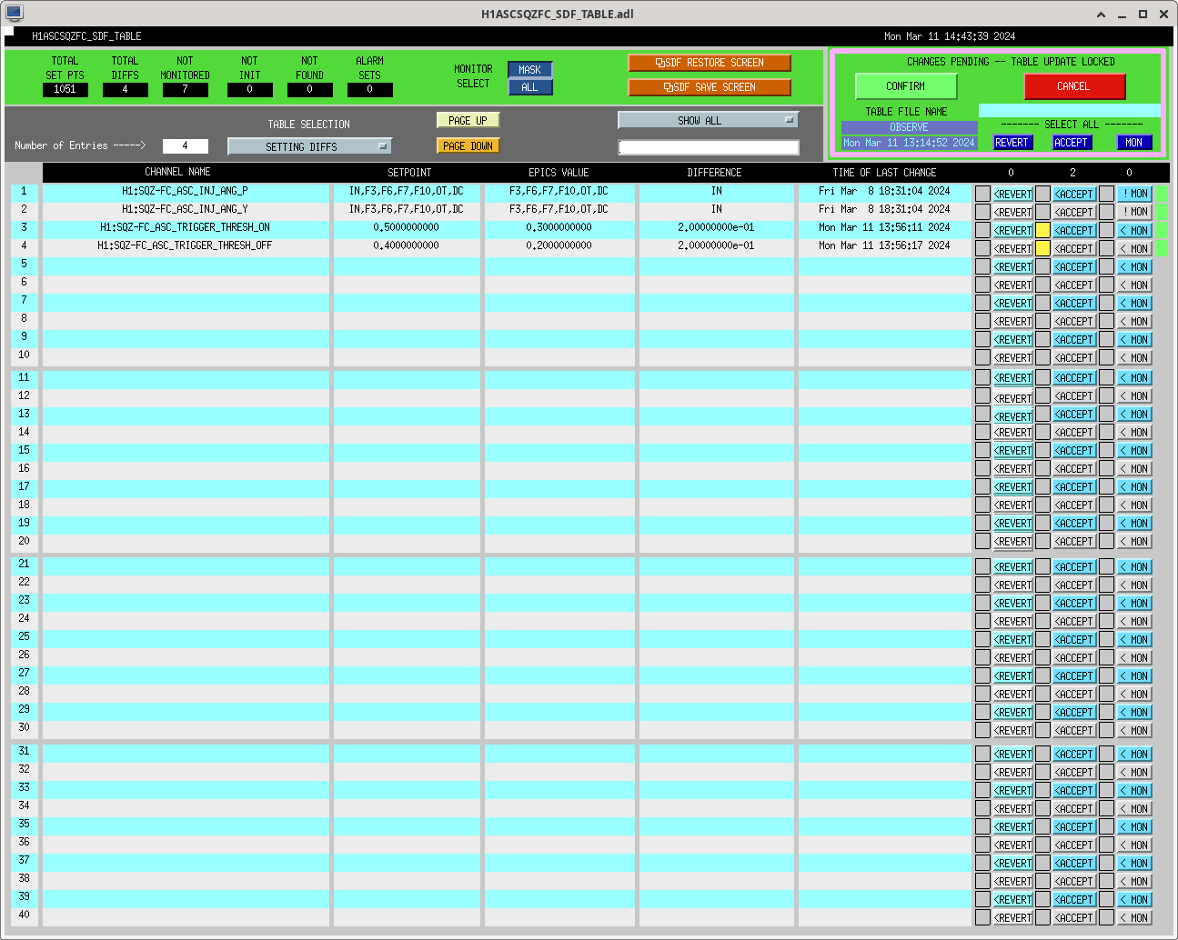
I reduced the FC ASC threshold as shown in the attachment. I also reduced the fcWFS_qDip_lock_threshold in sqzparams from 0 to -50000 although I am not sure if this is useful. 

Images attached to this comment
naoki.aritomi@LIGO.ORG - 13:34, Wednesday 13 March 2024 (76346)

The SQZ-CLF_REFL_LF_OUTPUT is 245uW now and was 5.7uW in O4a so the CLF power is 43 times more now.

camilla.compton@LIGO.ORG - 09:33, Thursday 14 March 2024 (76371)

Since the vent, we haven't recovered our squeeze in the region of  that really improves our range: See Yellow BLRMS around 350Hz.

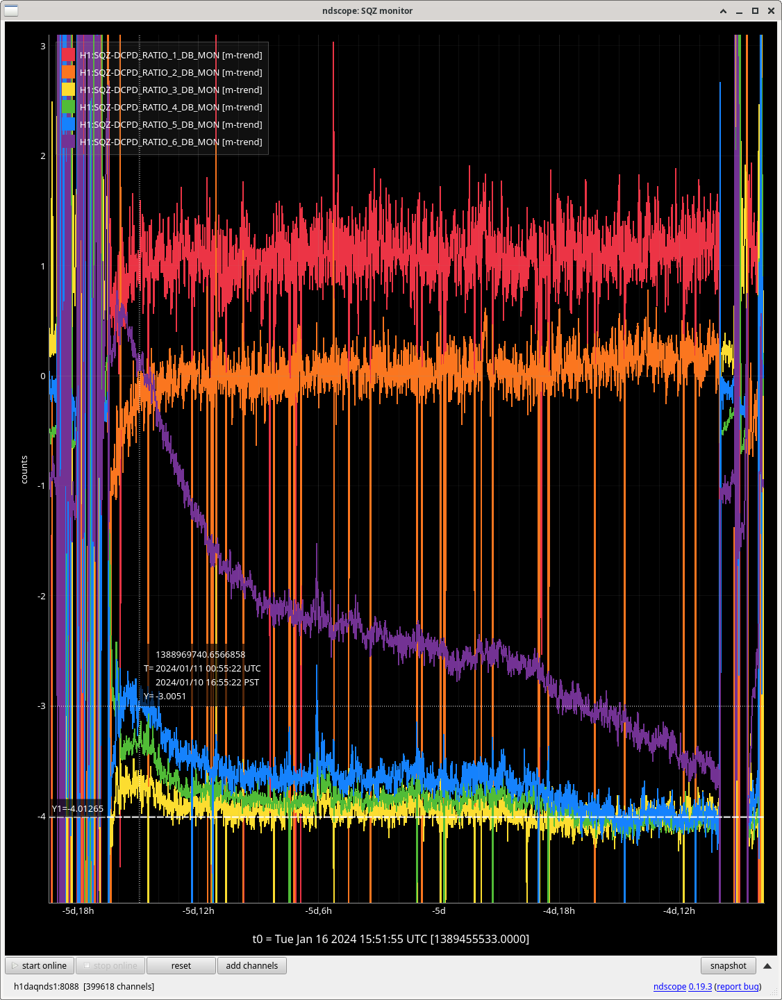
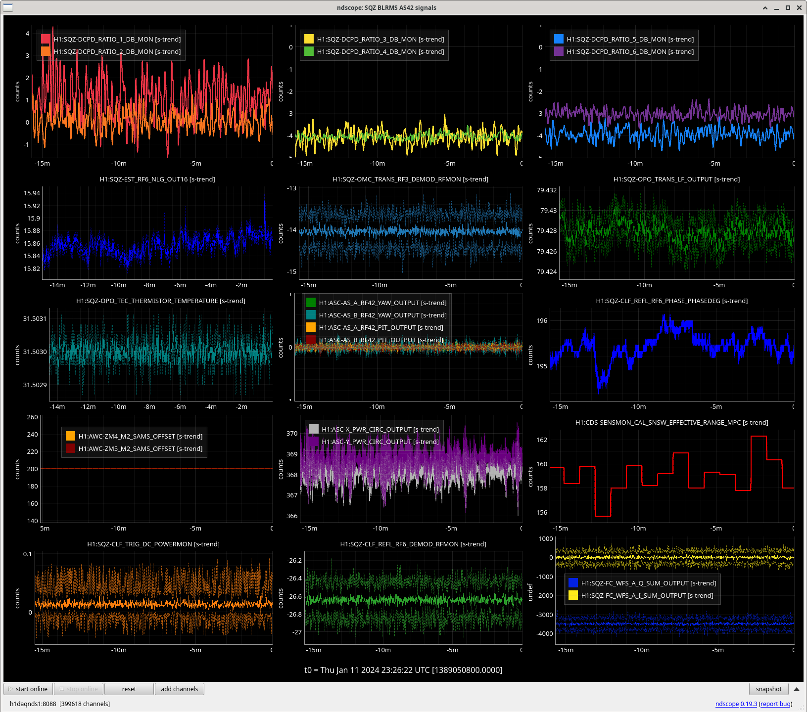
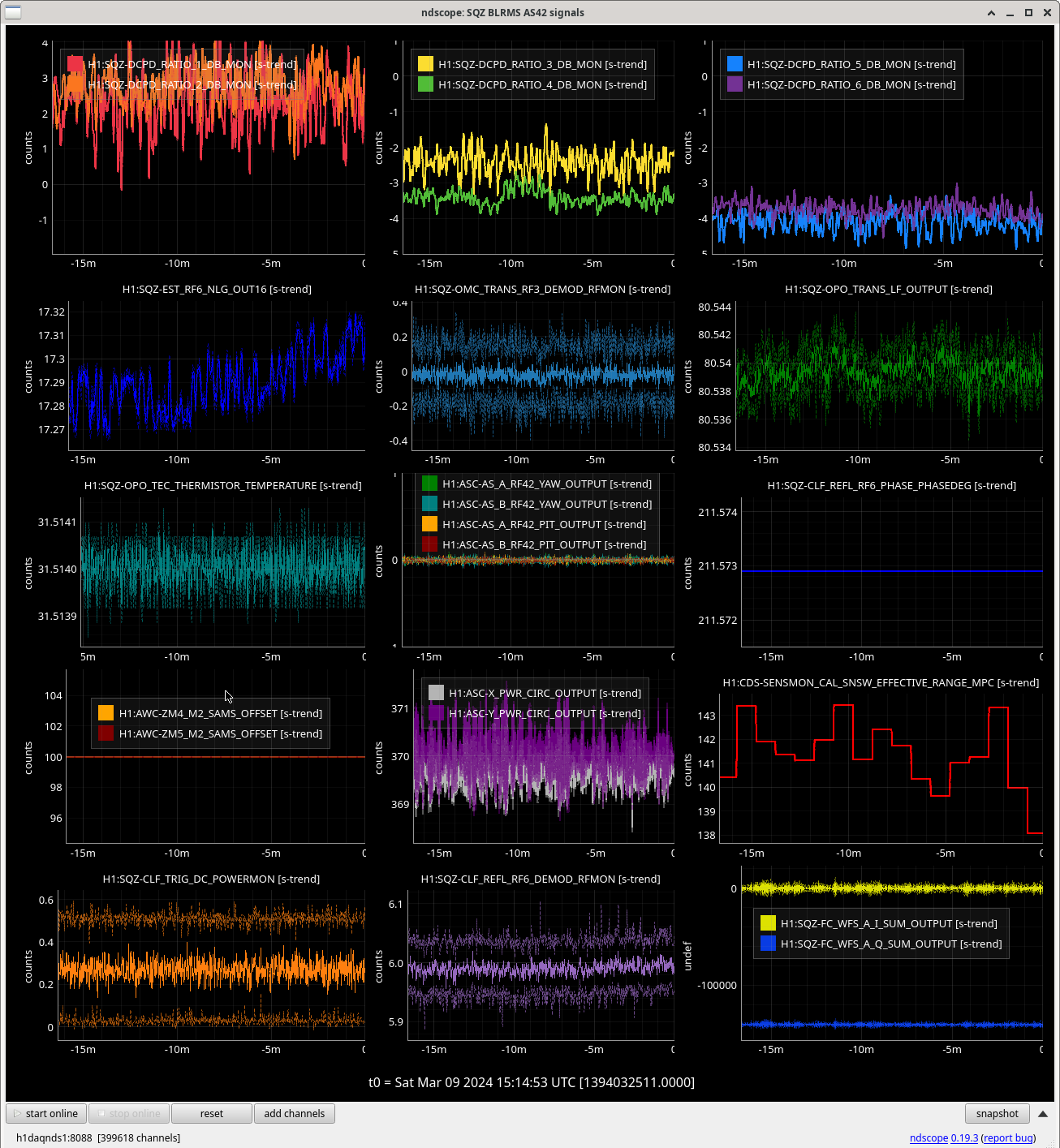
In O4a we had yellow (135Hz), green (broad 1kHz) and blue (1.7kHz)  around 4dB, plot of Jan 10th.  On March 8th we had good 4.5dB sqz above 1kHz but had  <3dB in the yellow bucket region, plot of Jan 9th.
We should focus on improving SQZ in the yellow BLRMs. Using: OPO temp, SQZ angle, ZM alignment. While optimizing BLRMs should watch ADF frequency, currently at 800, but notched in BLRMs at 1300Hz.

Checked SHG pump launch is ~20.5 - 21mW at both times and OPO green trans rejected is similar.

Trending our other signals, just see that OMC_TRANS_RF3 and CLF_REFL_RF6 and FC_WFS_A_ locking signal sare much larger, I think this is expected from increased CLF power. The NLG is simular 15.8  now, was 17.3. Plots of Jan 10th and March 9th.

Images attached to this comment
Displaying reports 15001-15020 of 89144.Go to page Start 747 748 749 750 751 752 753 754 755 End