TITLE: 01/13 Eve Shift: 00:00-08:00 UTC (16:00-00:00 PST), all times posted in UTC
STATE of H1: Lock Acquisition
INCOMING OPERATOR: Ryan S
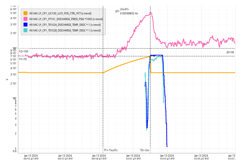
SHIFT SUMMARY: Lockloss early on in my shift due to an ETMX WD trip (75358), and after running an initial alignment and getting past all of the lower state locklosses, we've been sitting in OMC_WHITENING for three hours waiting for the DCPD values to lower.
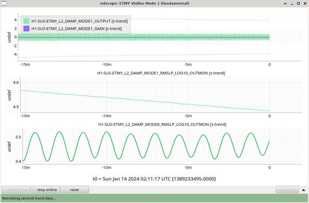
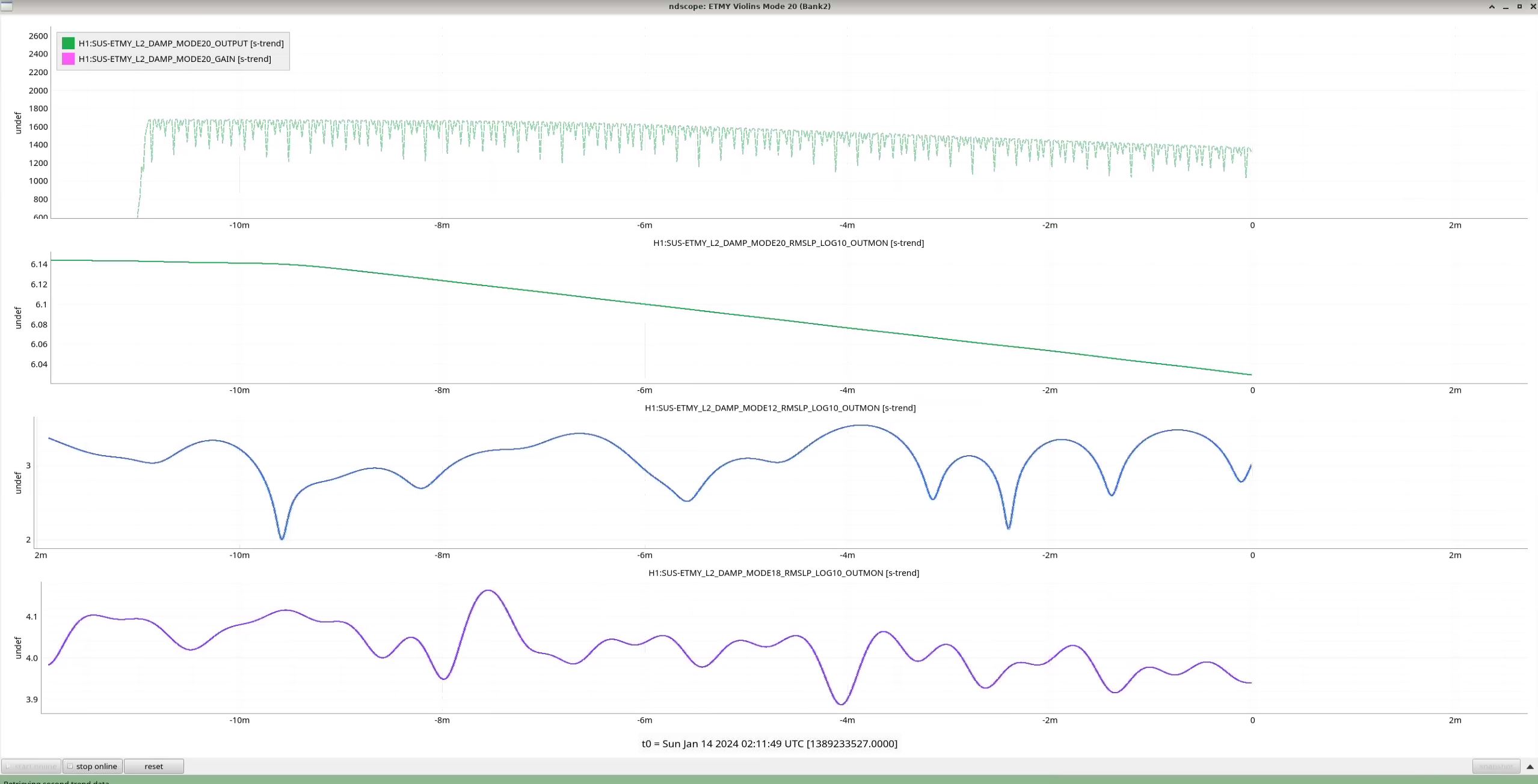
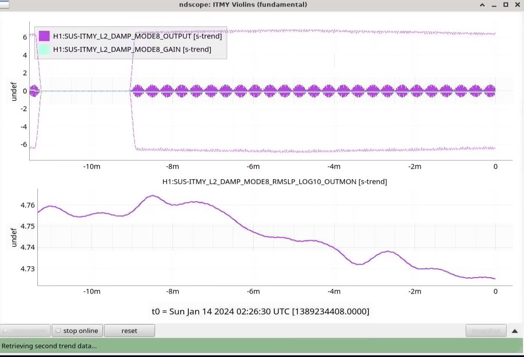
The violins are very high and ITMY5 and ETMY1 started rising, so I changed ITMY5 to be -0.02 (nominal = +0.01), which worked to lower IY5/6, and turned off the gain for ETMY1, which sort of worked only in that it made ETMY1 level off, but isn't damping.
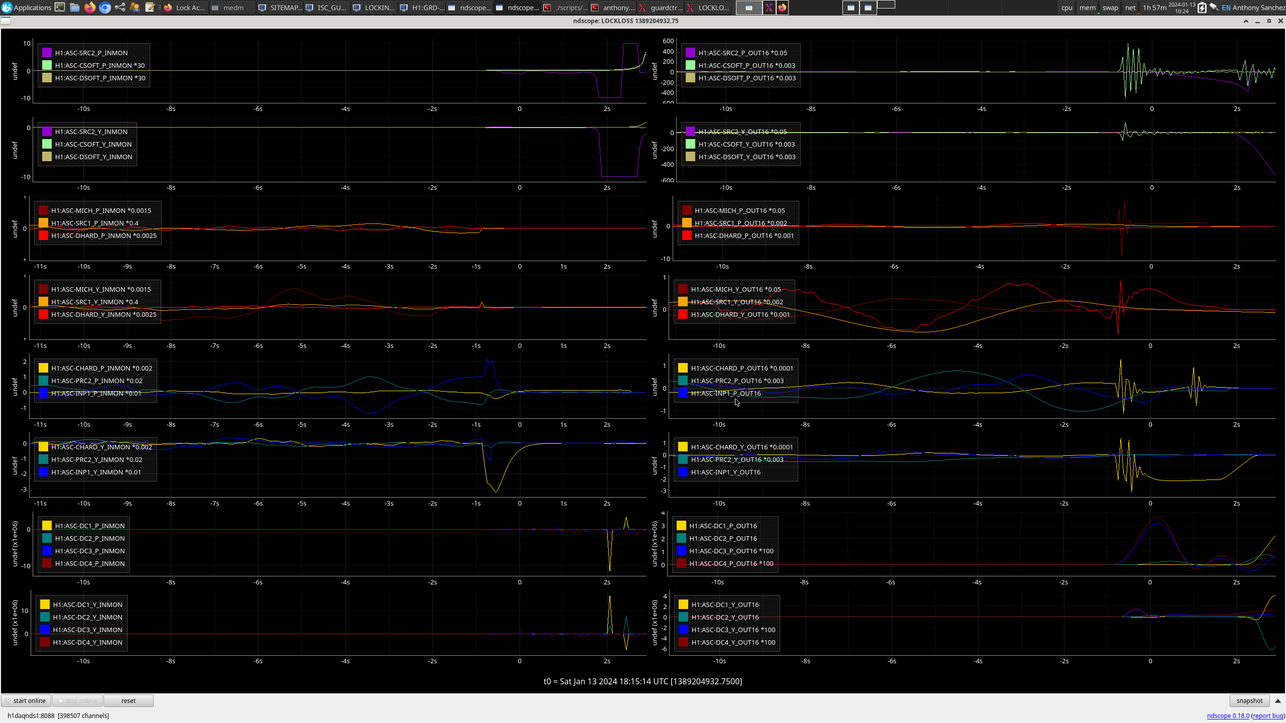
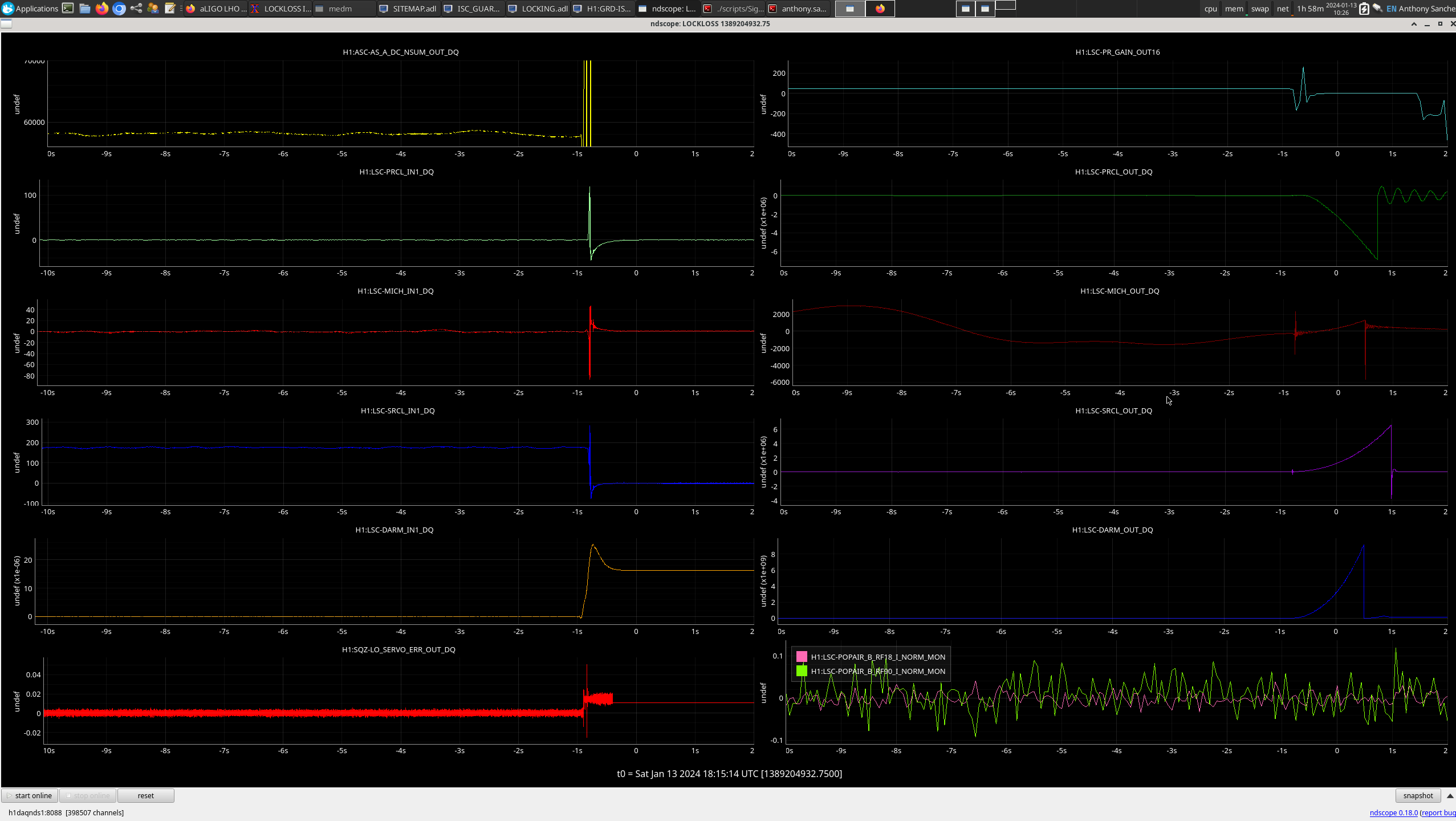
Right as I was about to post my alog, we lost lock due to watchdogs tripping for ITMX ISI, and for ETMX ISI, SUS, and HEPI. Currently have Ryan S on Teamspeak to pass the ifo over to him/troubleshoot.
LOG:
00:00UTC Detector Relocking and in LASER_NOISE_SUPPRESSION
00:09 Reached OMC_WHITENING
00:31 NOMINAL_LOW_NOISE - went into NLN during a low point in the DCPD's oscillation, so moving into NLN started causing saturations soon after
00:32 Started getting verbal warnings for PI 31, DCPD, and PI 24, and PI 28, so Jenne changed the OMC_LOCK state to REMOVE_WHITENING while we wait for the DCPDs to go down
01:20 Jenne fixed an error in the OMC_WHITENING waiting state that caused us to prematurely turn on whitening (75359)
- Jenne manualed us back to OMC_WHITENING
- Reloaded ISC_LOCK
01:31 Lockloss due to ETMX HEPI, SUS, and ISI WD trip (75358)
01:51 Started relocking by taking us to GREEN_ARMS_MANUAL
01:58 FMC-MY_AH_REHEAT_DEGF red alarm - FMC-MY_AH_REHEAT_DEG temp exceeded 119F
- Looks like MY AH had gone up to 128F 9hours ago, and Austin had already tagged FMCs then (75325)
02:33 Lockloss from FIND_IR
02:44 Lockloss from CHECK_MICH_FRINGES
02:48 I started an INITIAL_ALIGNMENT
03:13 INITIAL_ALIGNMENT completed, starting relocking
03:36 Lockloss from DRMI_LOCKED_CHECK_ASC
- We had been cycling through ACQUIRE_PRMI -> PRMI_LOCKED -> PRMI_ASC -> LOCKLOSS_PRMI -> back around to ACQUIRE_PRMI multiple times before getting through and locking DRMI, before losing lock a couple of seconds after getting into DRMI_LOCKED_CHECK_ASC
04:01 Paused at CHECK_VIOLINS_BEFORE_POWERUP to try damping the violins before increasing power
05:07 Reached OMC_WHITENING, waiting for violins/DCPD counts to lower
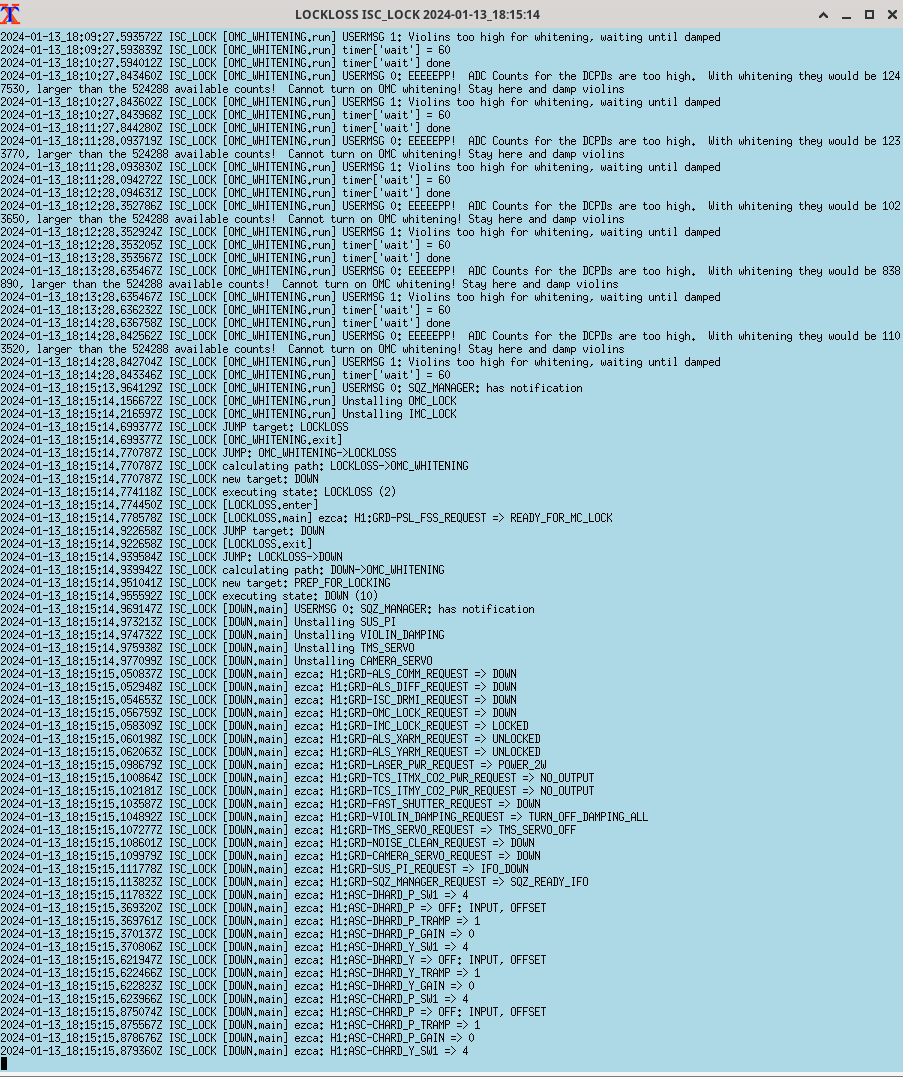
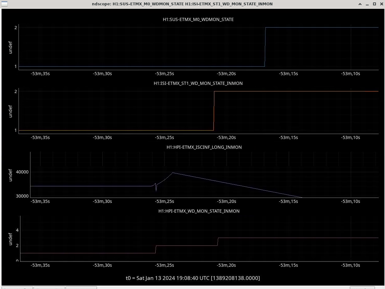
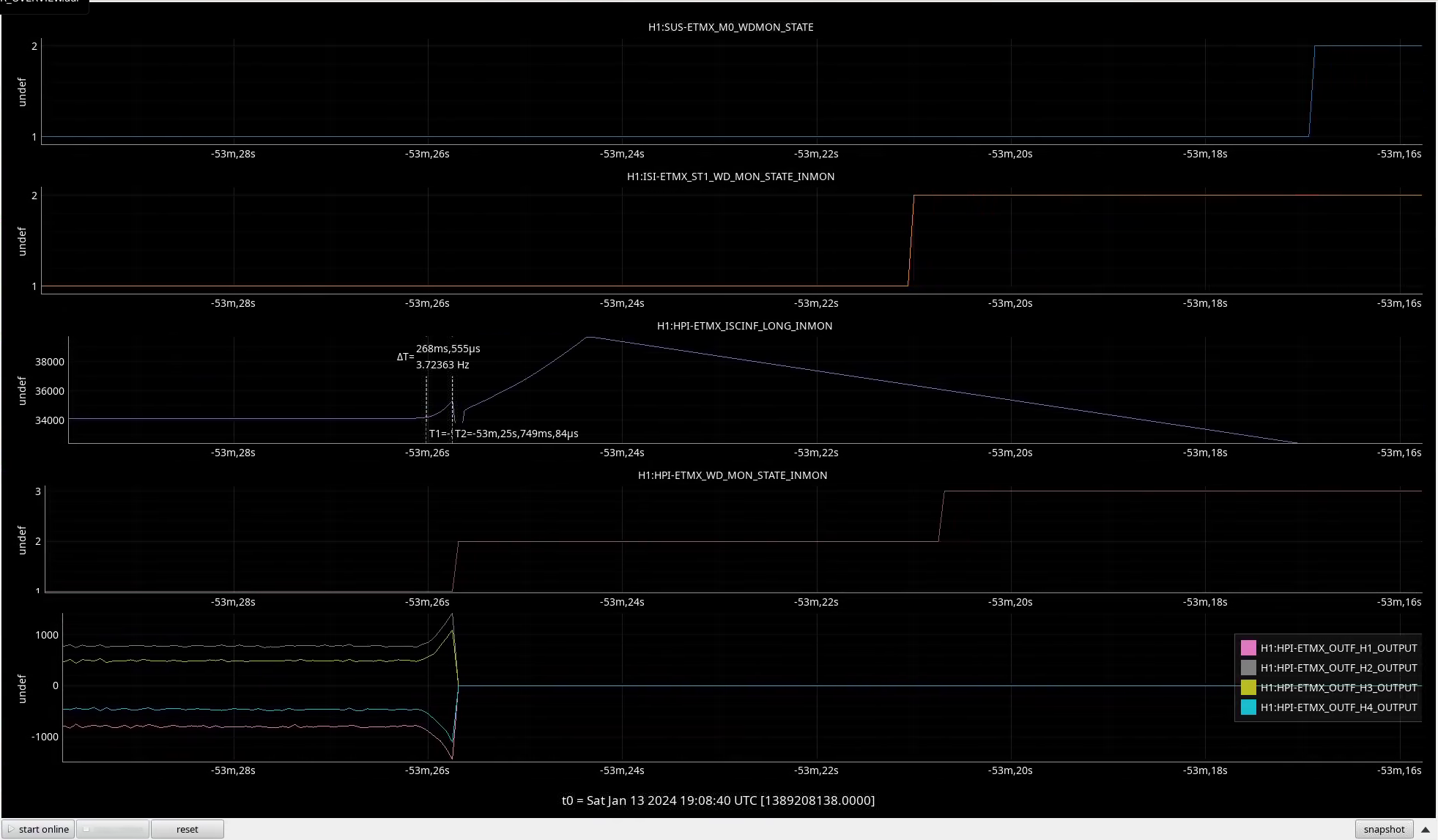
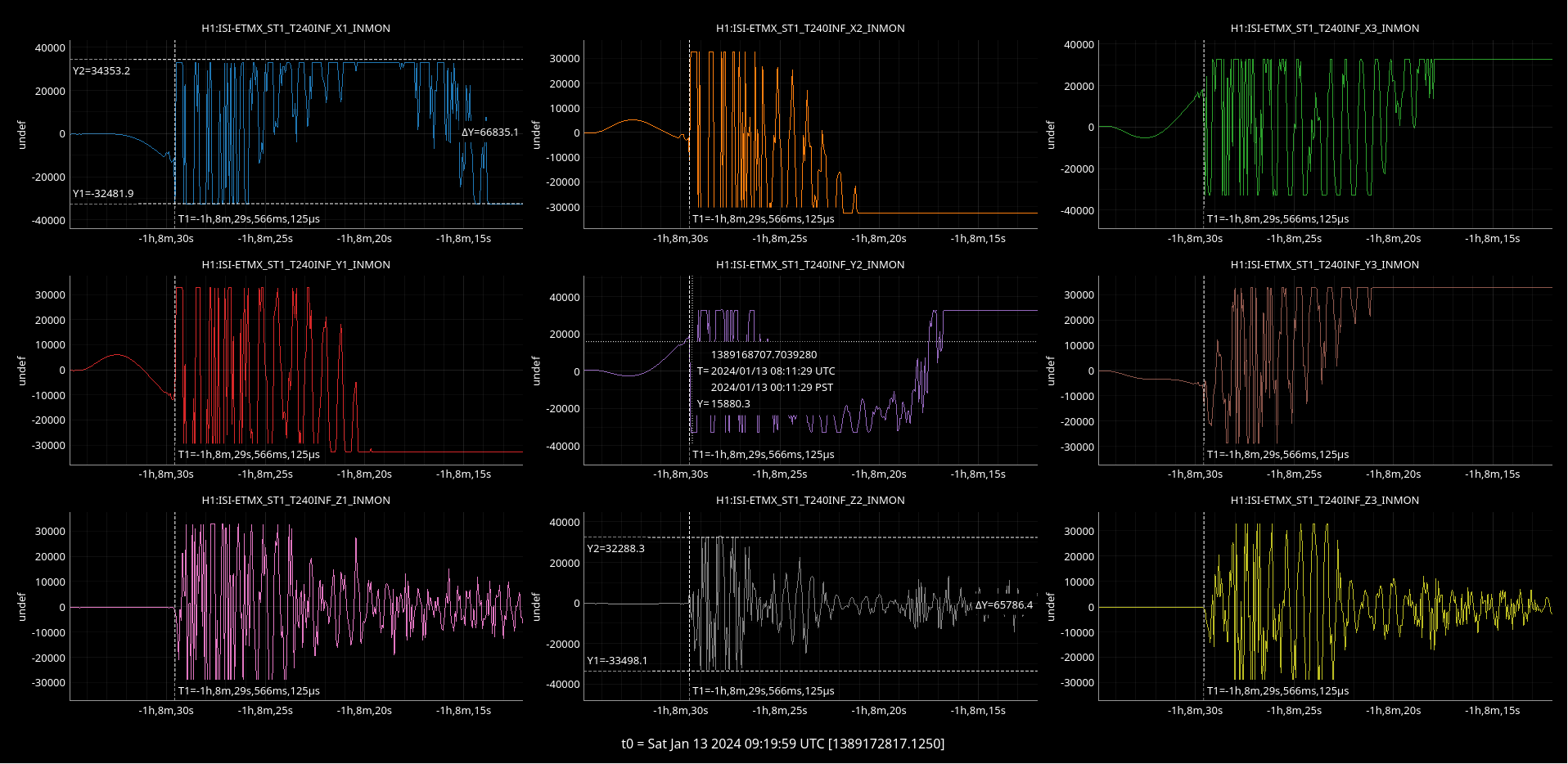
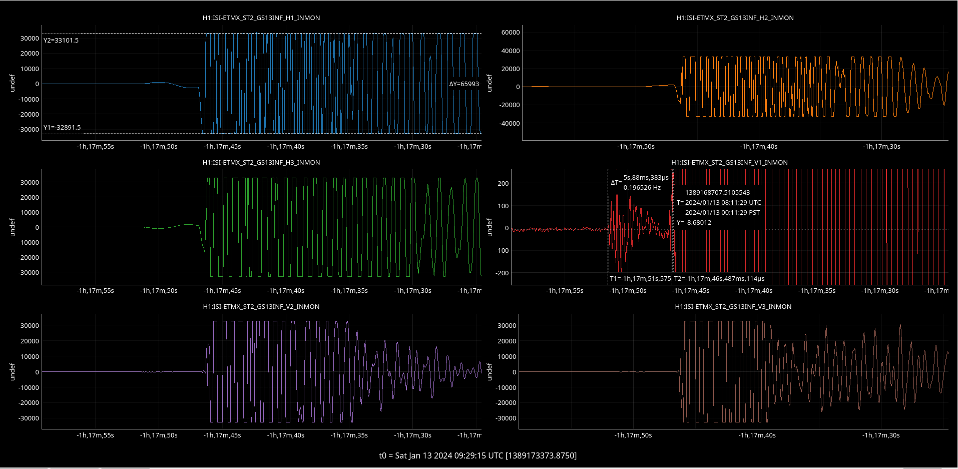
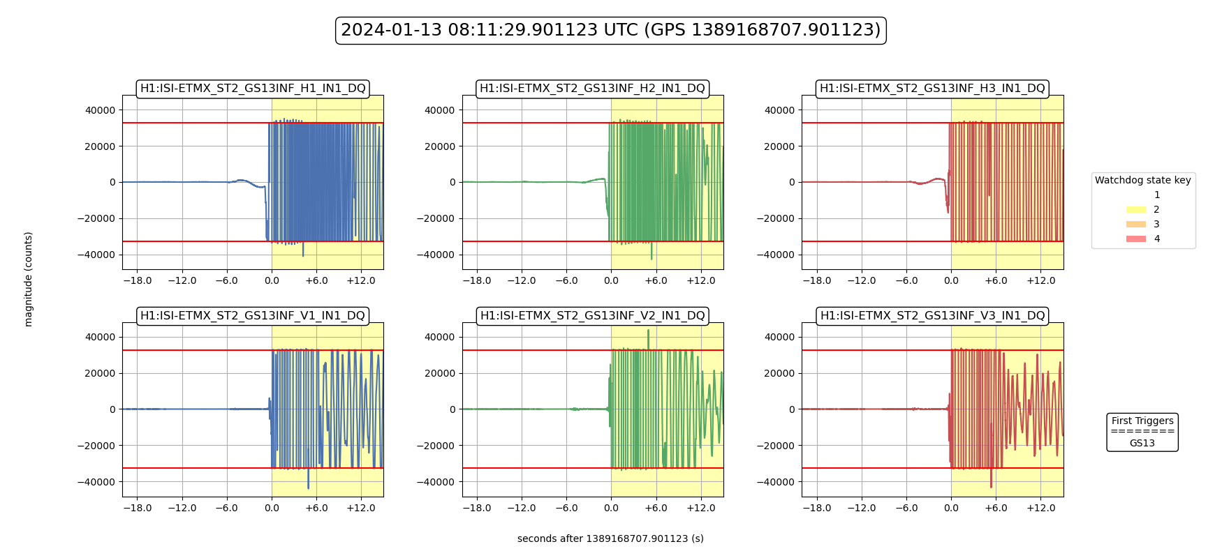
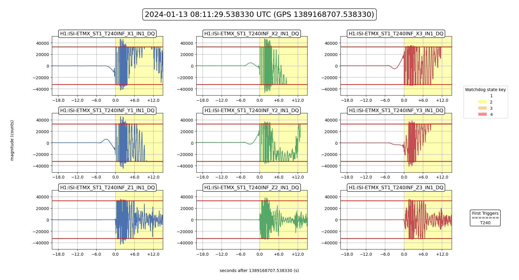
08:11 Lockloss due to WD trip for ITMX ISI, and for ETMX ISI, SUS, and HEPI