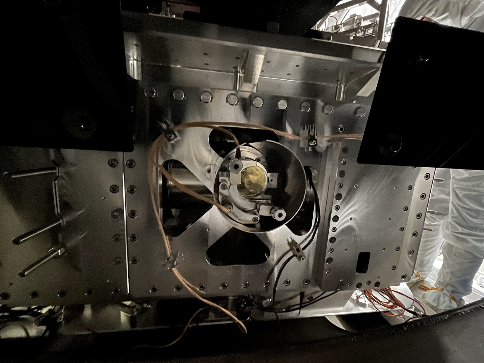
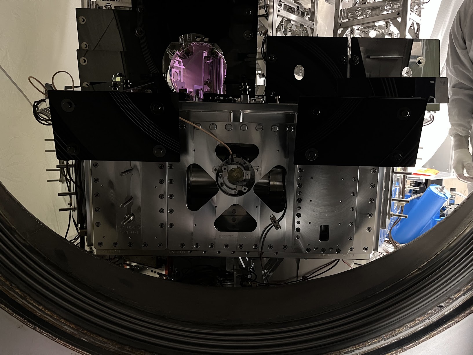
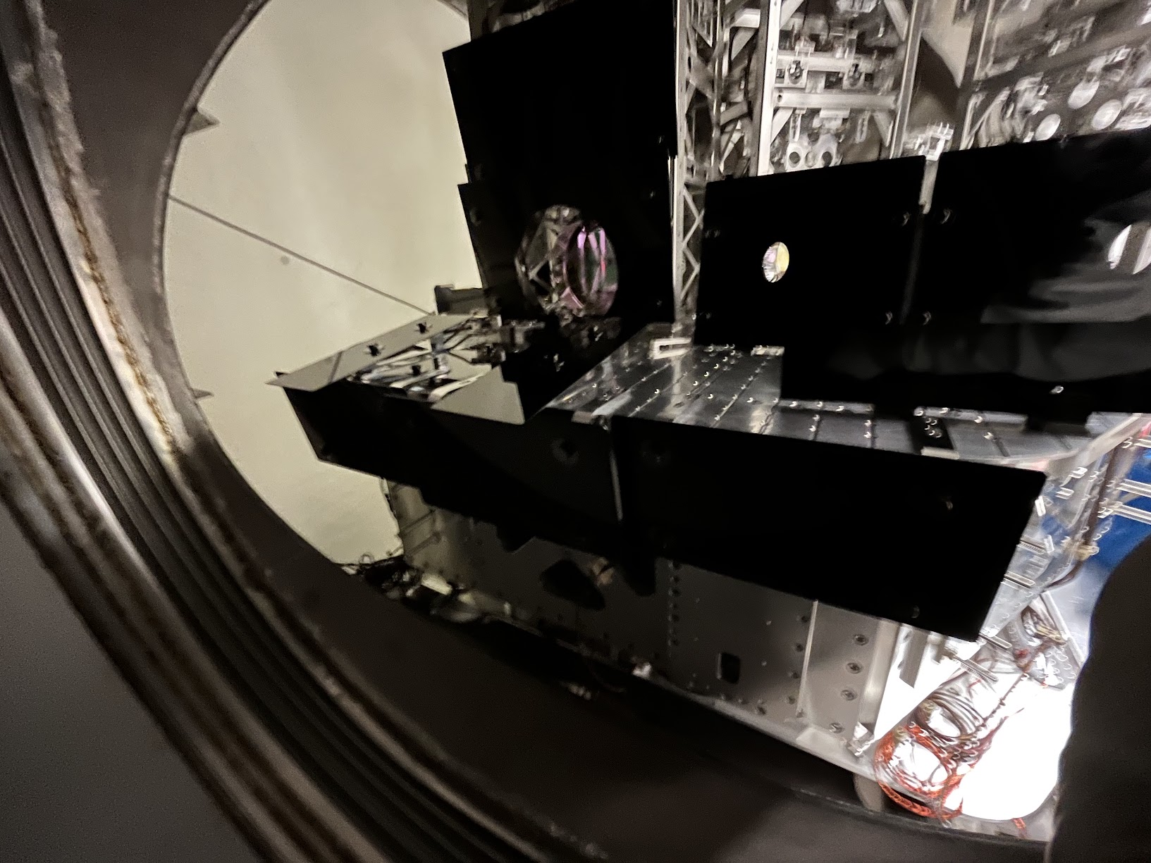
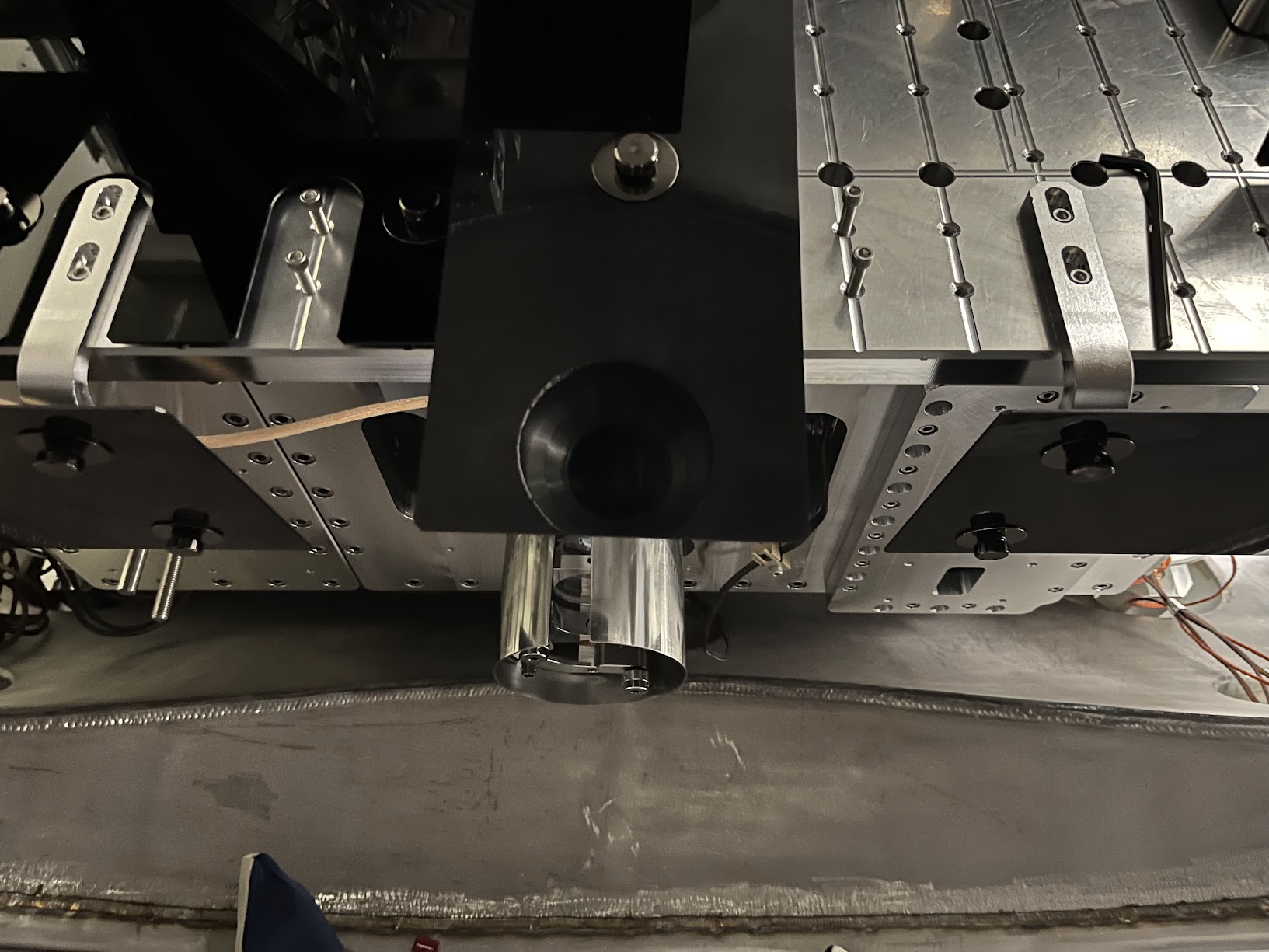
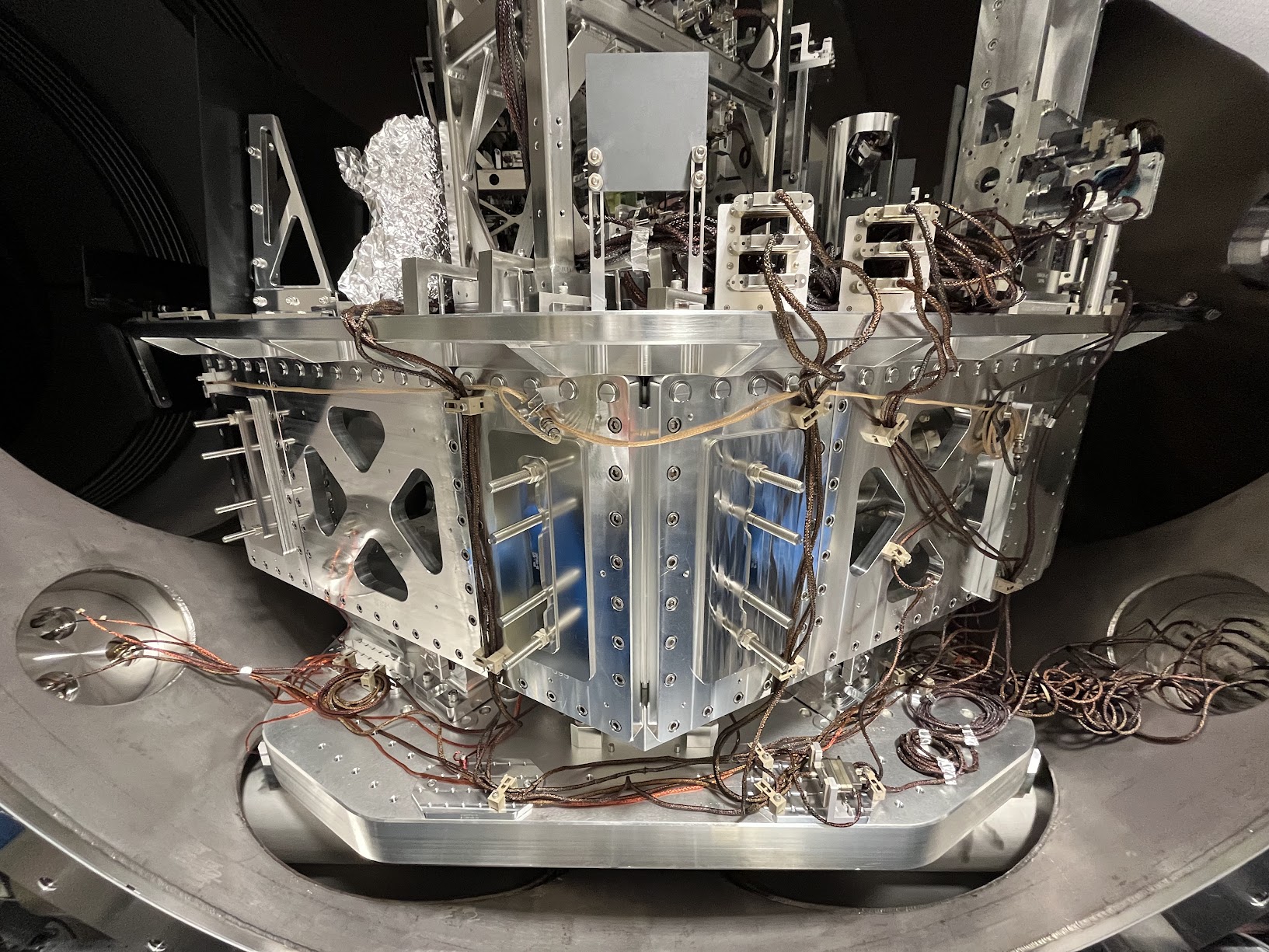
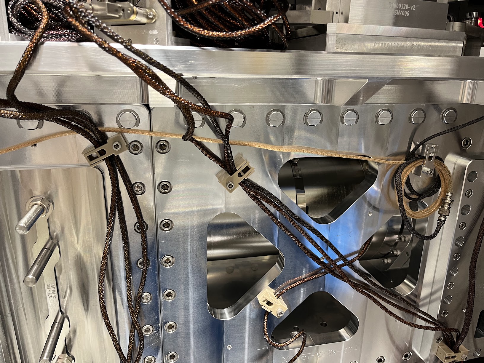
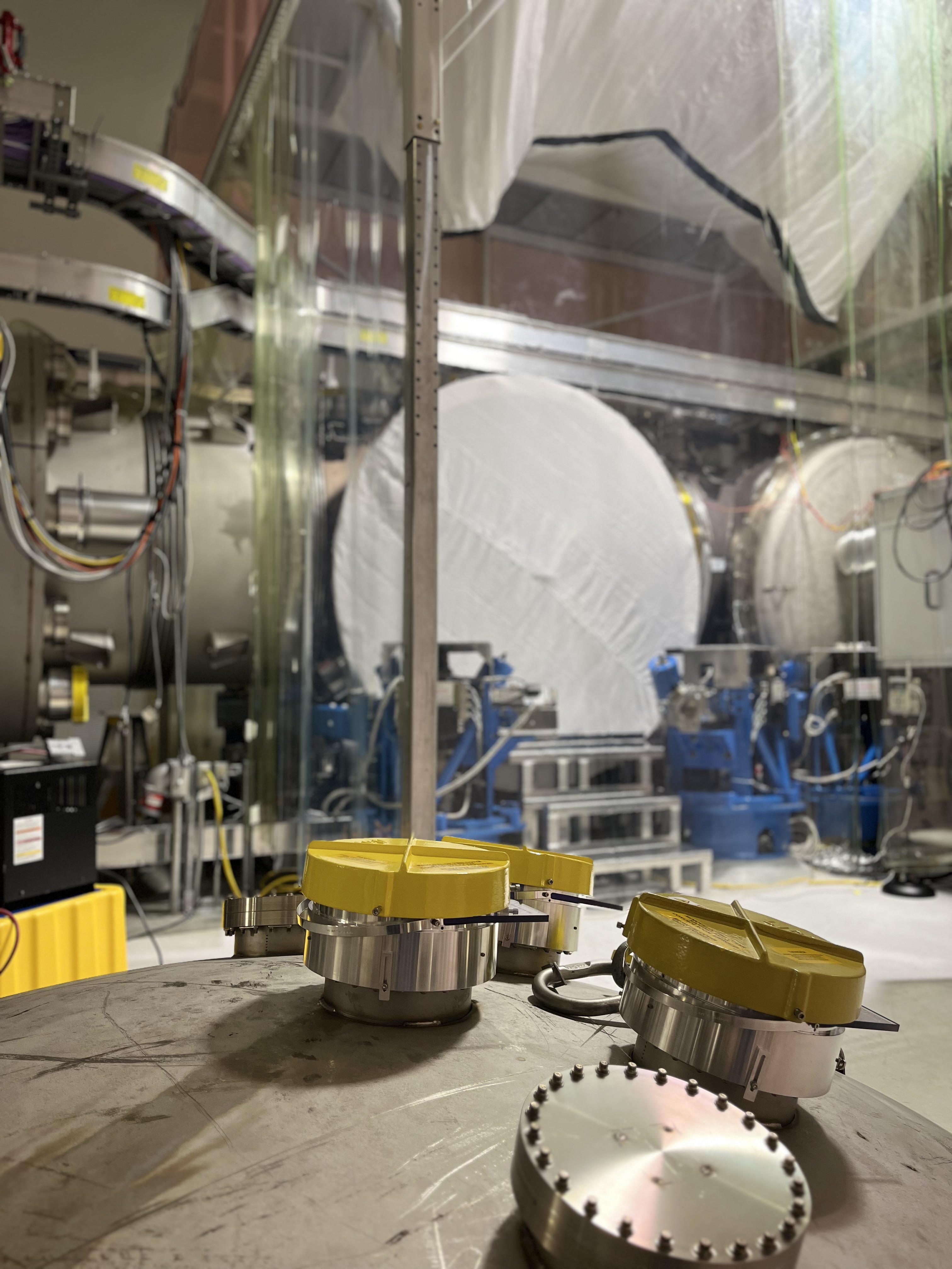
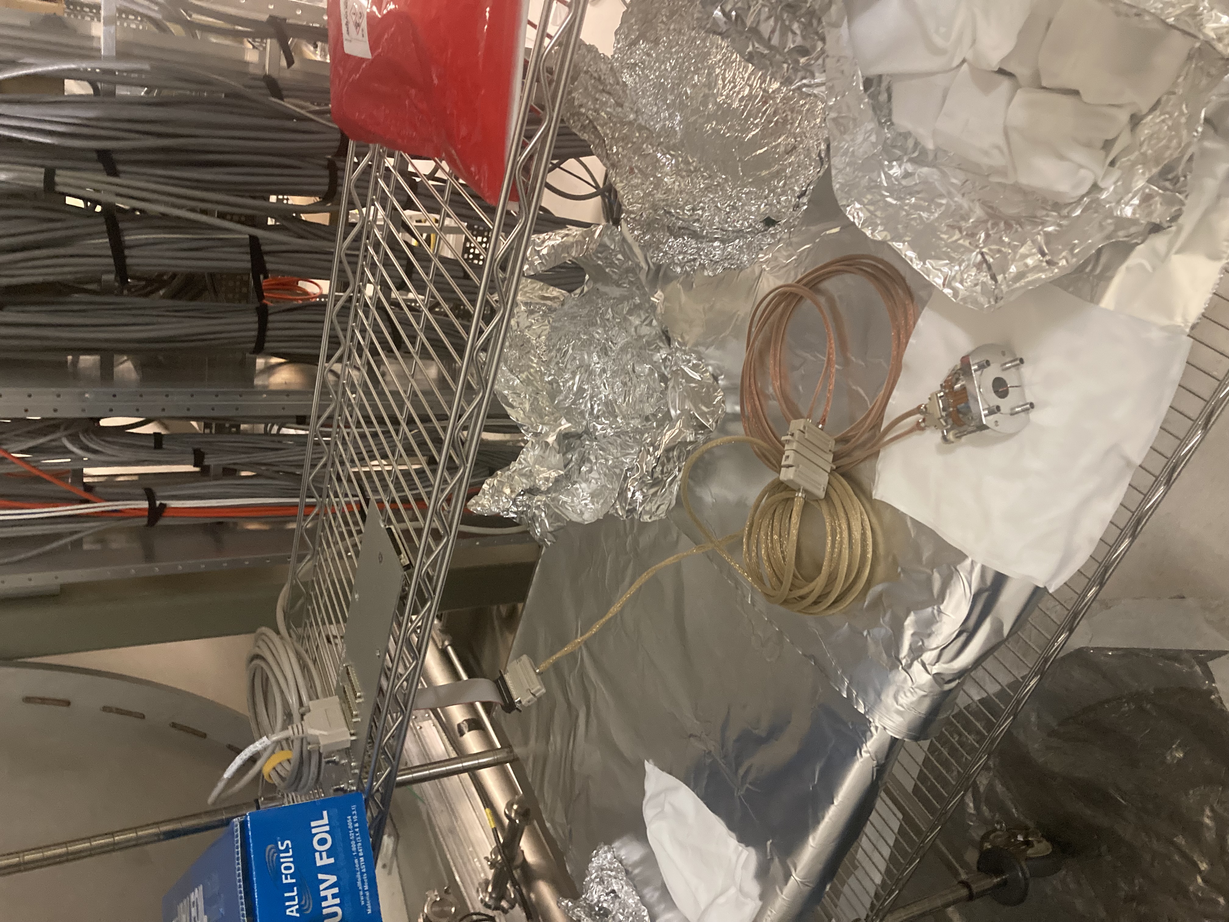
J. Kissel, J. Warner ECR: E2400026 WPs: 13237, LHO:13238 Final Design Doc: T2400145 Relevant Systems Level Drawings: . Mechanical Assemblies :: ISIJ Reflector D2400102 :: HAM Table Baffles D1700335 :: HAM2 Systems Layout D0901083 (not yet-inclusive-of-SPI) . Electronics Wiring Diagram . Cable Routing In-vac Cable Routing Plan from G2401479 (pages ) . Flange Layout D1002873-v11 Executive summary: - Removed ISIJ +X-side, center, HAM2 ISI table baffle from D1700265-v4 Type 2 :: Bracket mounting bolts left screwed into ISI optical table for this will eventually become a D1700265-v4 Type 3 and remounted. - Installed ISIJ Reflector + QPD Assembly D2400102 on +X ISI side wall (D071057-v2), with its shroud (D2500030) in place :: We didn't weigh it, but the SW Assembly predicts a mass of 1.96 [kg], which we can likely round up to 2.0 [kg] with the shroud installed. - Routed and connected QPD read-out cable system to D3 flange, F10 spigot. - Routed and connected picomotor cable system to existing D1101515 quadrupus leg Cable #3, J4 :: Cable #4, J5 is connected to IO PM5 mirror, Cables #2 J3 and #1 J2 were reset in neat coil with connectors floating to avoid electrical grounding as before. - Nudged make-shift baffle system using D1700261 ballast mass baffle mounted vertically on the +X / +Y / Beam Height corner of the chamber wall upon entry into beamtube. :: the will DEFINITELY need a technically-minded reset. In at 10:30a PT and out by 12:30a PT. It's so lovely when everything goes to plan! Pictures and further info to follow in the comments below.
Removing Center ISI Table Baffle Not much to say more here -- removal was easy. We tried "just" removing the panel using the the coated/capped screws, but these didn't budget upon several attempts with Jim's fingers and grunts. So, elected to fight that battle outside the chamber and removed the whole assembly at the table mounting point. The full assembly is wrapped in dry-wipes, foil, and ameristat bagged and in Mitch's office while it waits for the Type 03 version of the panel to come out of clean-n-bake.
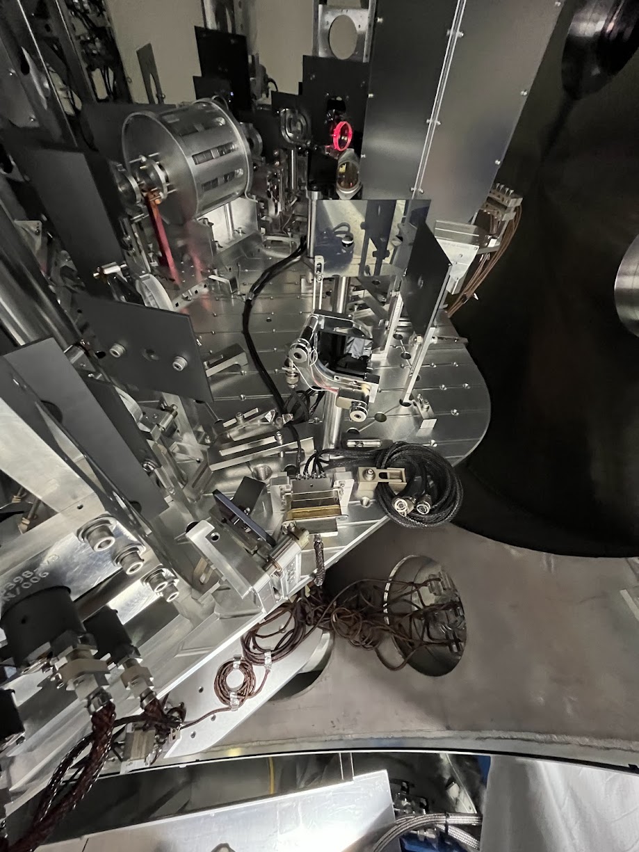
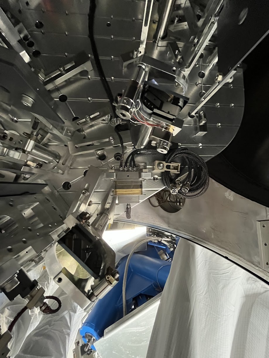
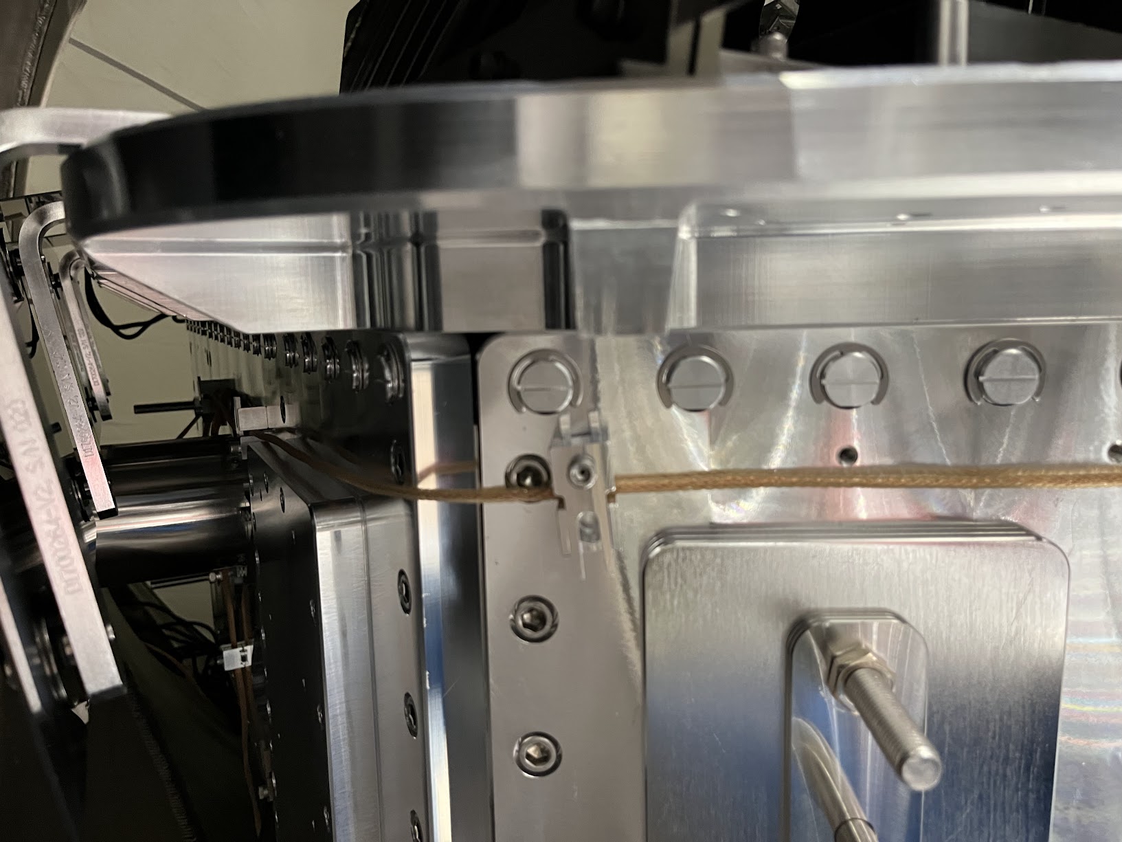
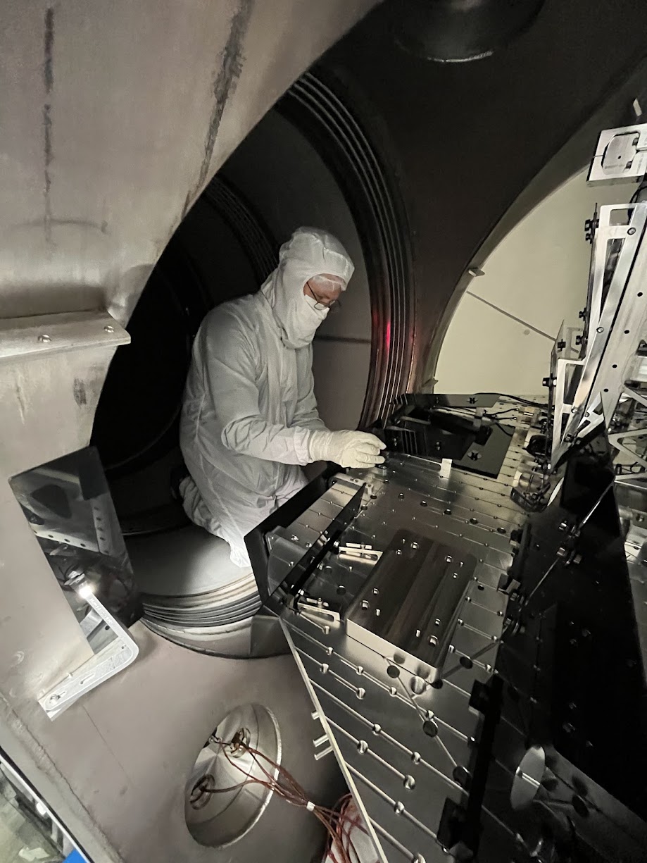
Installation of ISIJ Reflector itself Also not much to say, other than the great joy that the drawings of the D071057-v2 ISI Side Wall have the irregular positions of the 1/4-20 utility holes accurate enough that Bram's CAD-informed-only mounting holes for the ISIJ reflector's baseplate of the reflector lined up without issue. *phew* Also -- the D2400102 drawing doesn't highlight which length 1/4-20 bolt should be used for mounting, so we used 1/4"-20 x 0.625"L (5/8"), which was "just enough." Pictures from the main entry are the best "big picture" views, but here I attach a few more in case the need arises.
QPD Cable Routing
We didn't get dedicated pictures of this QPD cable routing but,
- it follows the plan on page 22 of In-vac Cable Routing Plan posted to G2401479-v3,
- You can see the ST1 portion of it well-enough in the above pictures,
- Jim did the routing, so I trust that there's a healthy loop in the jump from ST1 to ST0, and
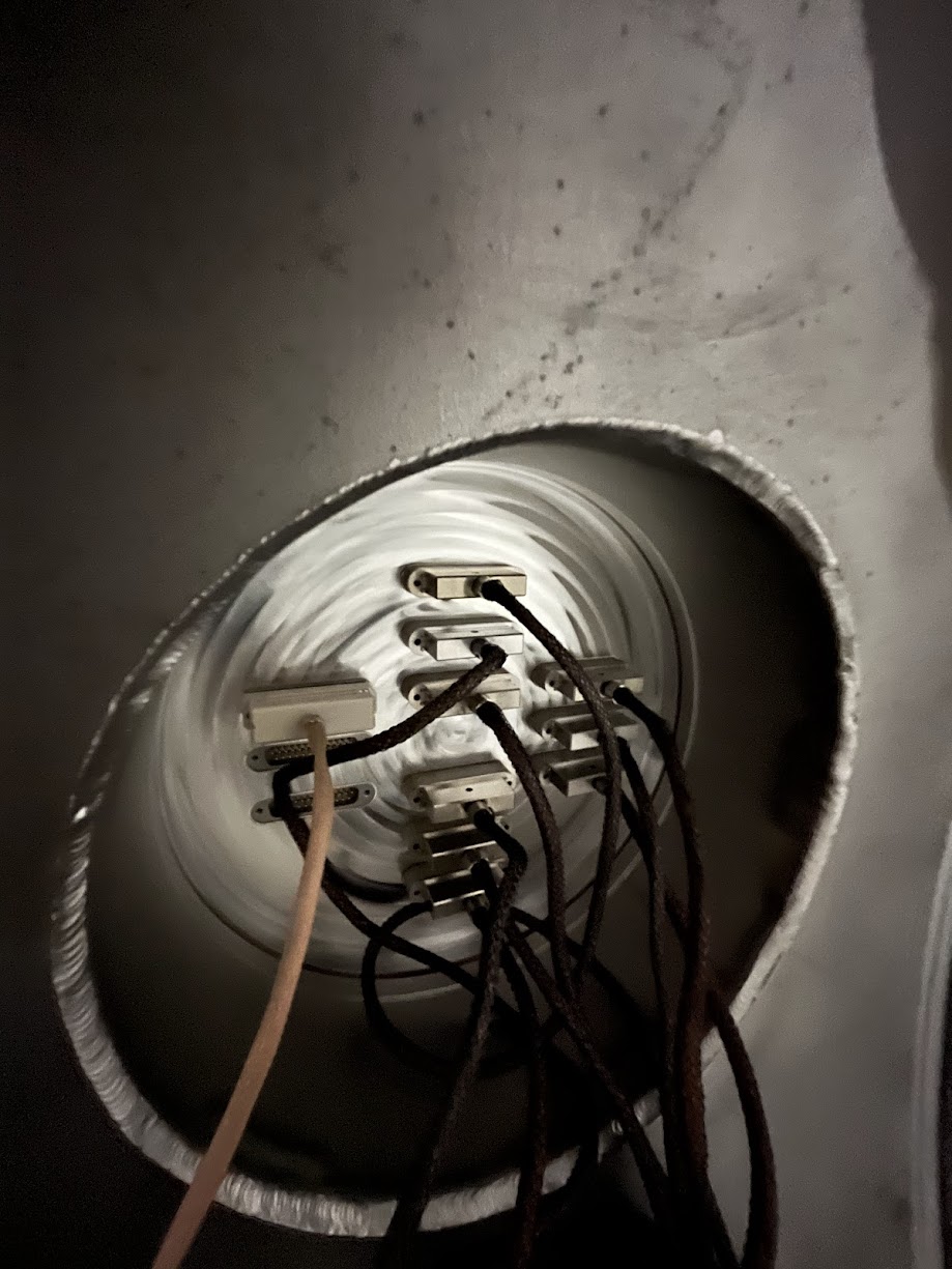
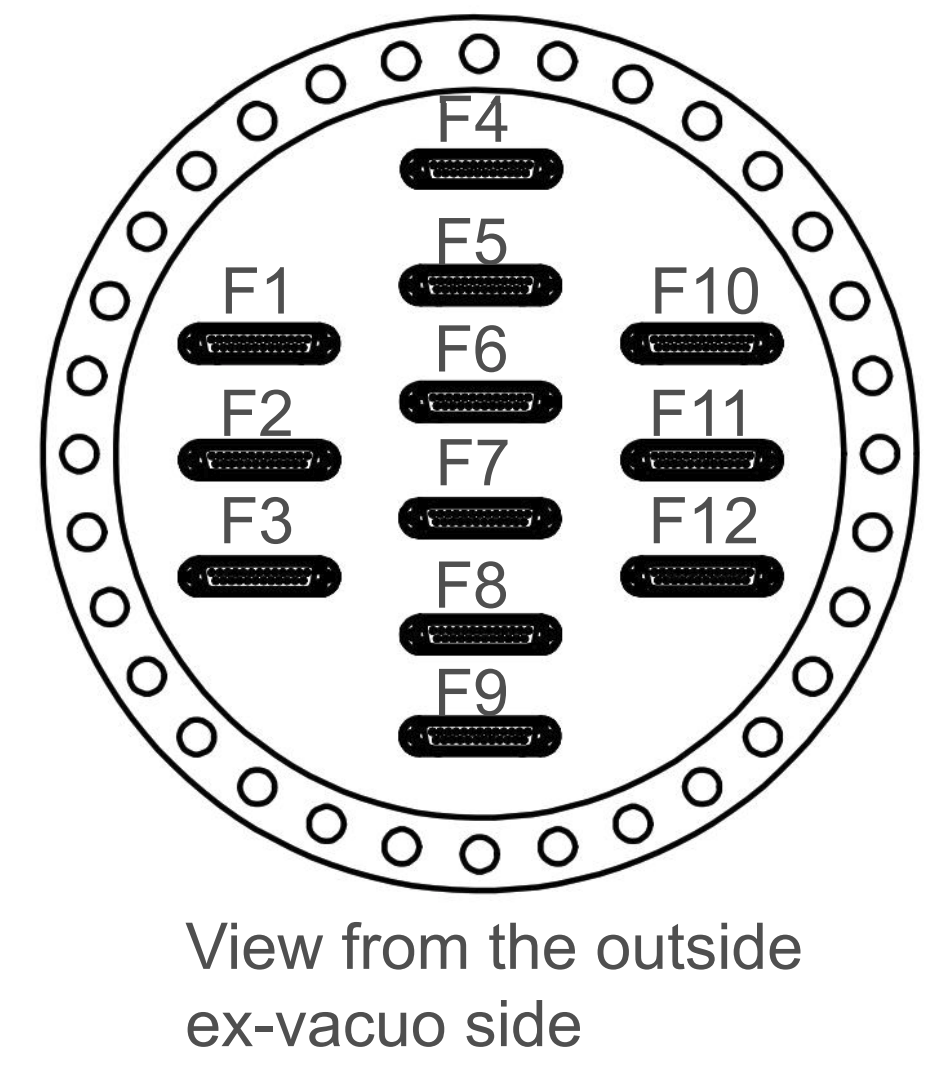
- I attach a picture here of the record that we've connected it to D3-F10, and a copy of the "F-Type" (D2000225-v1) counting from page 18 of the above mentioned cable routing plan.
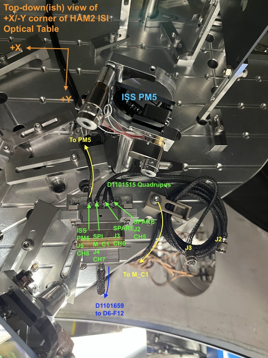
Picomotor Cable Routing BEFORE INSTALL Just because we knew little about the details of this cable system ahead of time given how ancient the PM5 picomotor actuated mirror system, I got a lot of good "before" pictures. Mostly, I confirm that PM5 does use the Cable #4 J5 leg of the D1101515 quadrupus, and all the other legs were neatly cable-tied up and away.
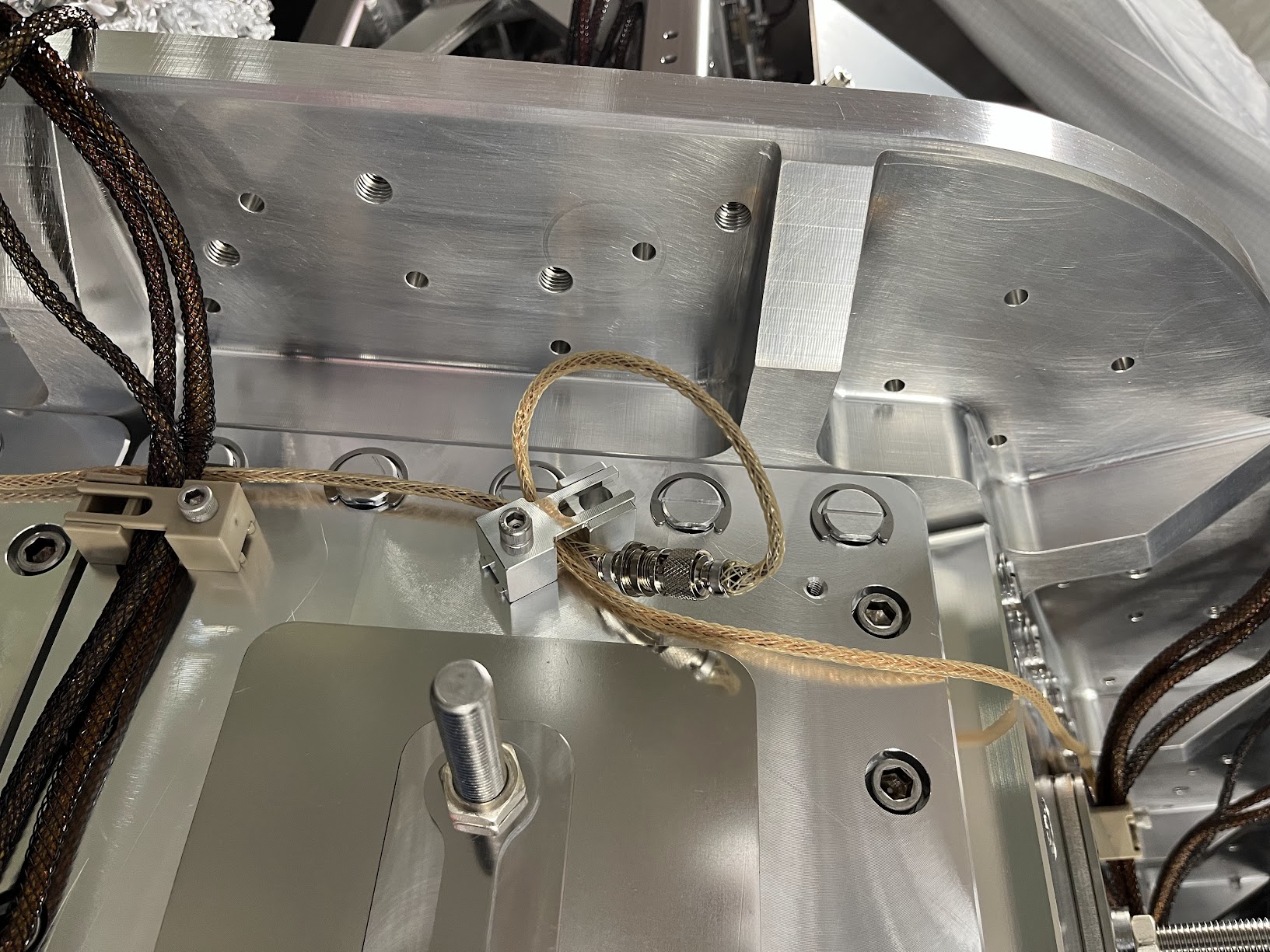
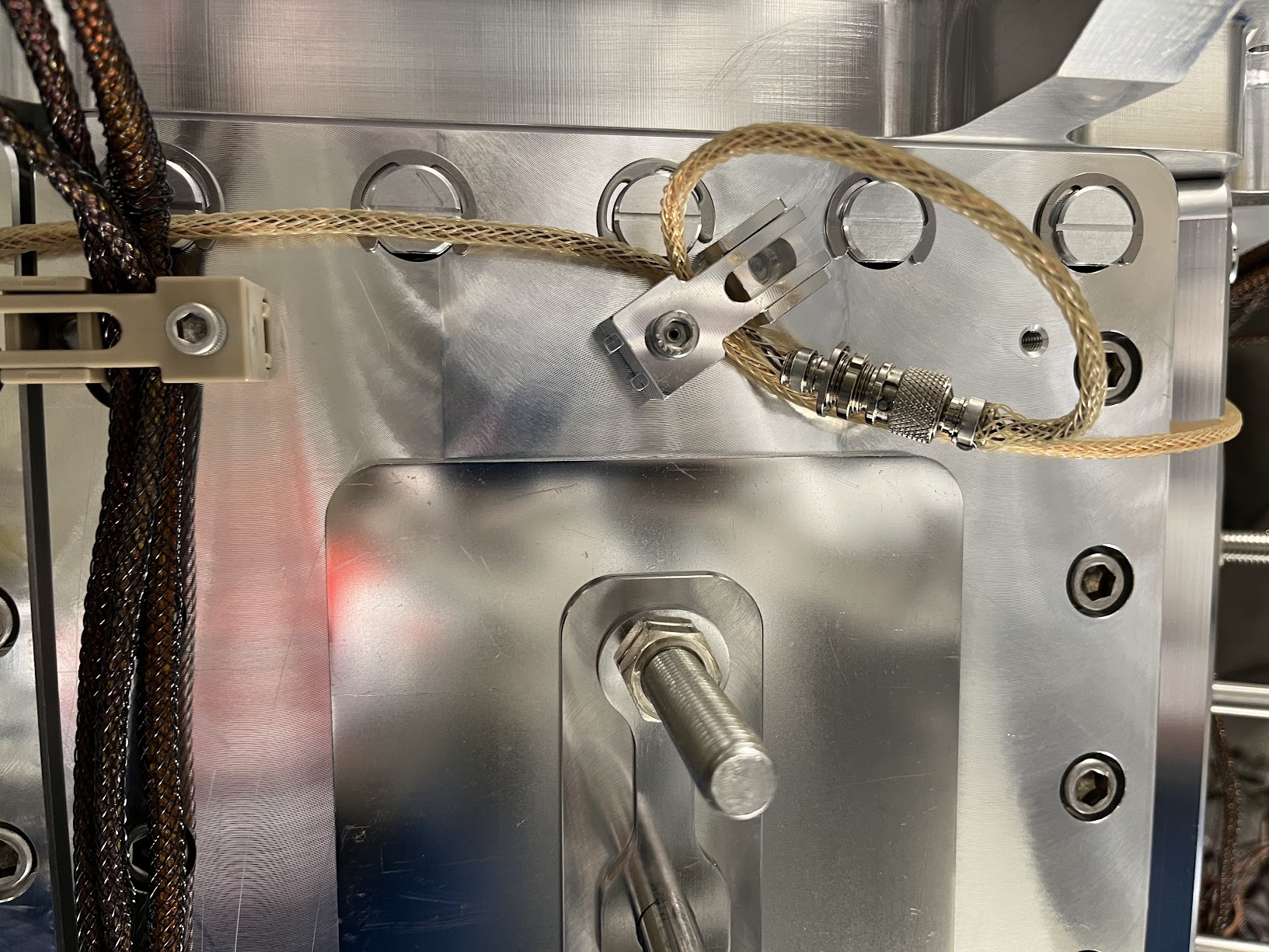
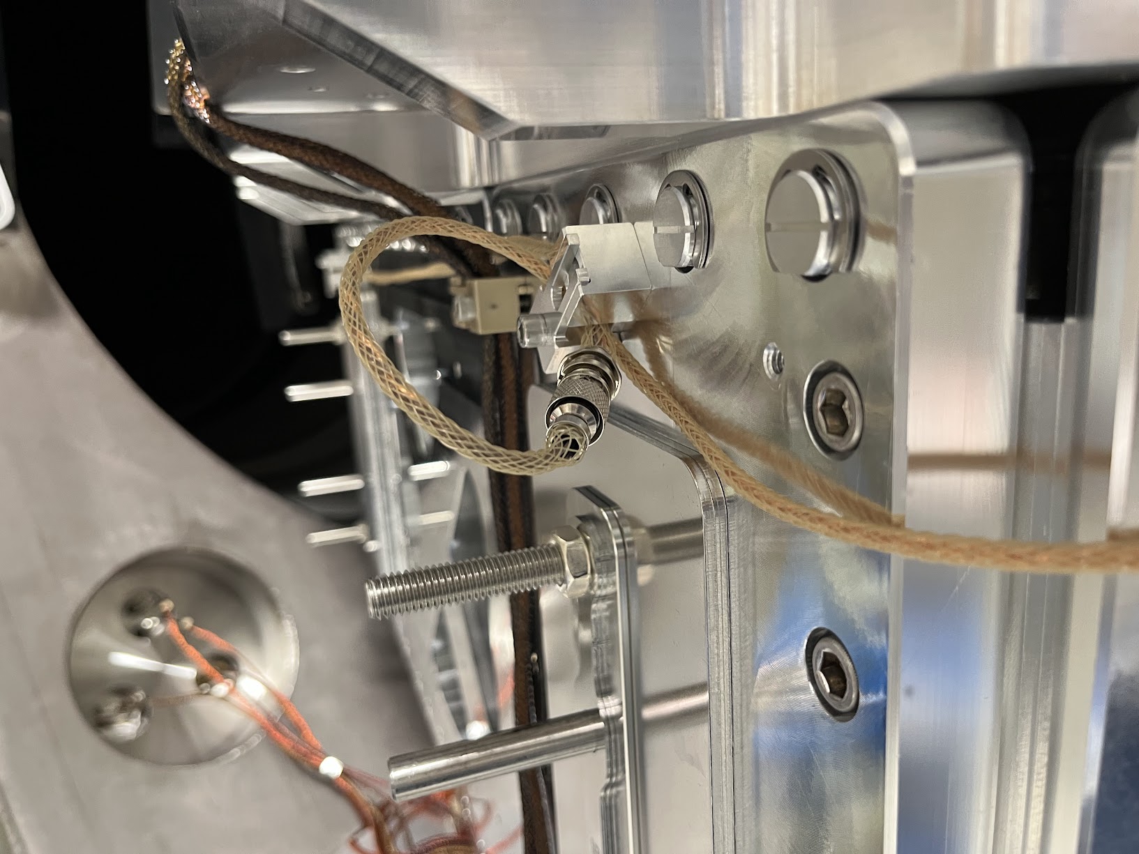
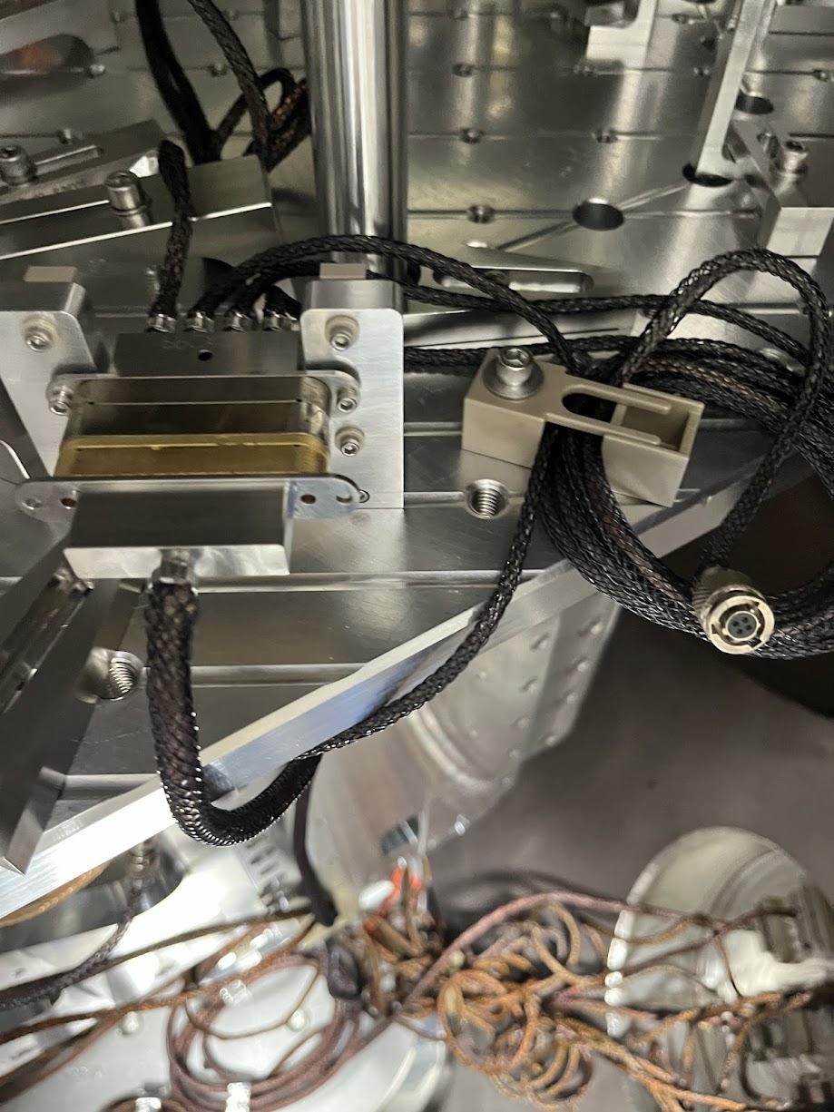
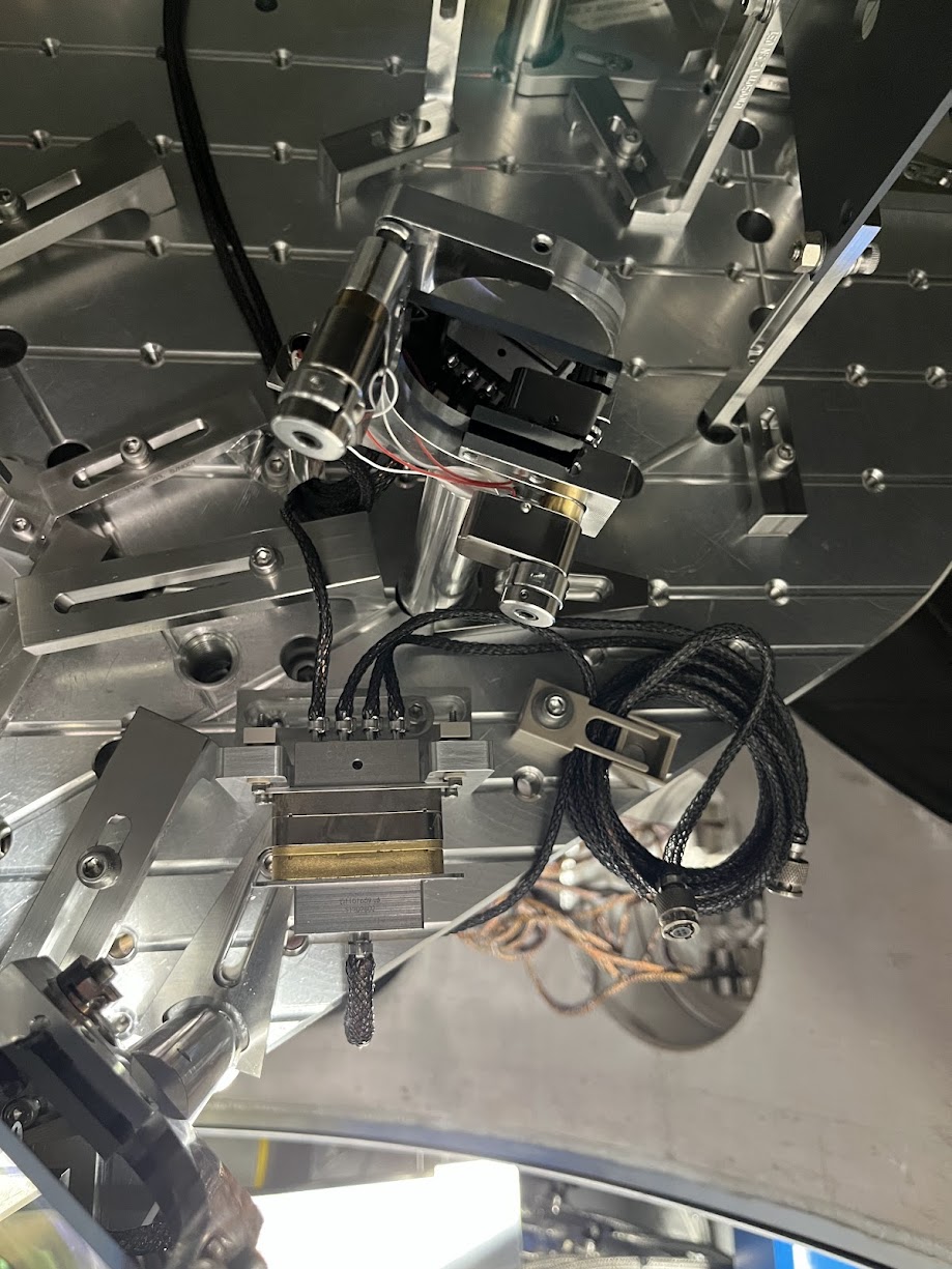
Picomotor Cable Routing AFTER INSTALL Here're photos of the routing of the two 72 [in] length D2400316 picomotor extension cables connected in series and routed to all the way around from the ISIJ reflector on the +X face to the -X / +Y corner of the table where CB-9 and the D1101515 quadrupus lives. I paid particular attention to the connectors and made sure they were left floating and not shorting to anything metal. I also re-bundled up Cable #2 J3 and Cable #1 J2 in coil similar to the before pictures, again ensuring that the connectors are floating in both space and electrical connection.
The Nudged Chamber Wall Baffle Some pictures of the baffle that we nudged that will likely need re-alignment.
tagging for photos.
On the new channel assignment of HAM2's SPI ISIJ picomotor, and why I'm confident it's CH7: Per D1000581-v13, page 13 and then D1900511-v12 page 17, I'm quite confident that the quadrupus cable and up in CH5-8 of the controller on IOT2L, called "PICOMOTOR 5" in D1900511, which I guess becomes "Picomotor B / Slot 2" on page 2 of the ECAT System Diagram D1100683-v11. This is corroborated with opening up the picomotor MEDM screen -- sitemap > LSC > picomotors > "HAM 2 + oplev" button (that has "controller 5" and "PICO B" next to it), and clicking through the channels and seeing that CH8 is called "PSL ISS QPD/PD (PM5)." Here's a labeled picture that makes things more clear.
Belated aLOG on in-vac cable routing of the ISIJ QPD A PD and serial number assignments:
Path PD Name PD SN Monopus D9-to-D25 Monopus
|----------D2600002--------|
D1600083 Type 3 D2400340 D2300128
OL ISIJ QPD A S2401092 S2500517 S2500511
Robert, Mitchell
During HAM3 chamber work yesterday the lower panel of the MCB2 panel was removed. This was needed for a clear path for the SPI. There were concerns that the removal would be difficult. The tolerence on the holes in the panels put strain and binding pressure on the screws going into the gussets. A few of the screws needed to gentle coaxing with patience and some Isopropal alcohol. Eventually they all came out without breaking or seizing. No pictures of the removal process were taken.
Pictures of the baffles added to HAM3 will be documented in a different alog.
The chillers have been turned on at the mid stations for the season.
FAMIS 28773
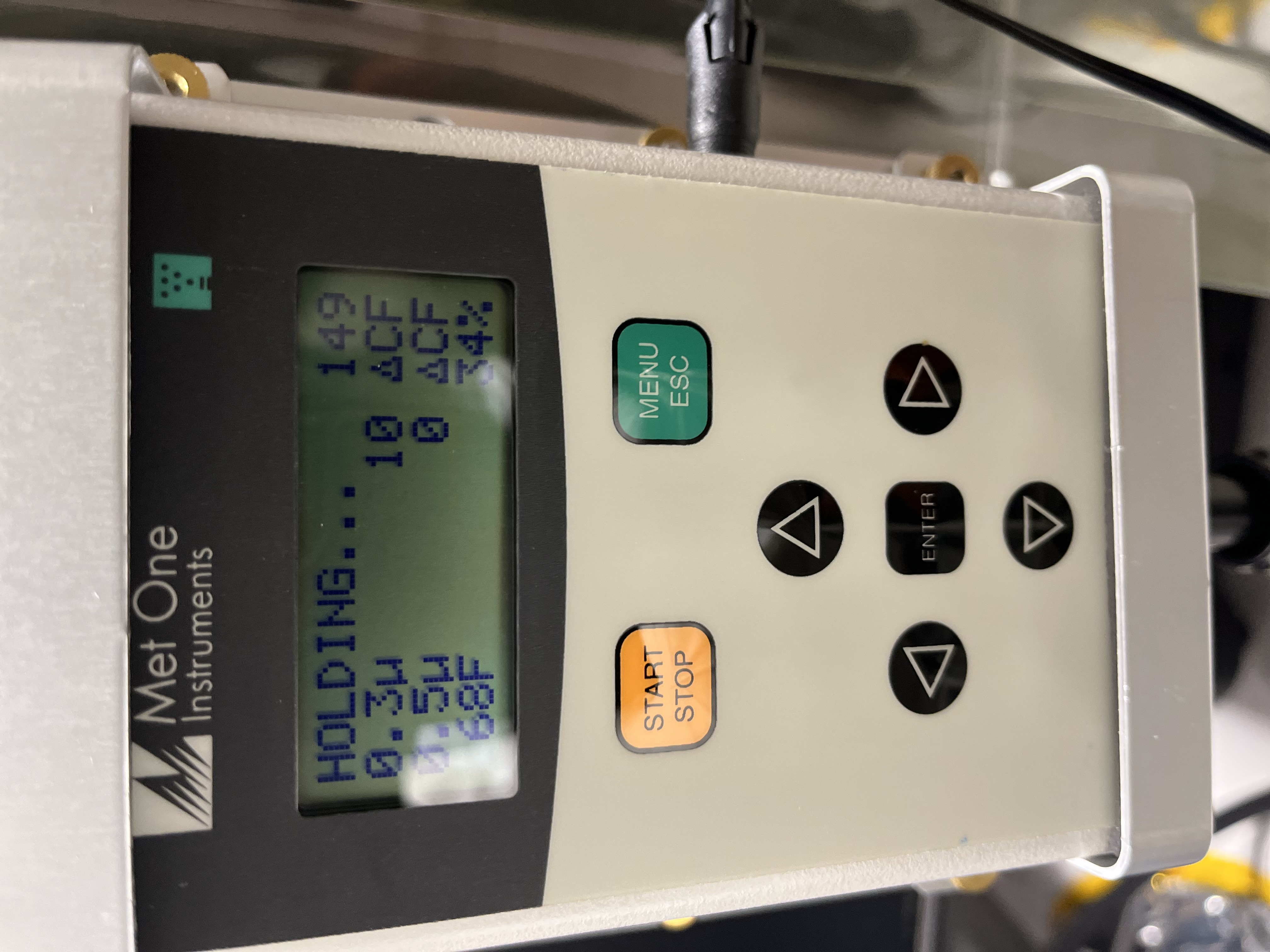
pH of PSL chiller water was measured to be between 10.0 and 10.5 according to the color of the test strip.
The MC2 SW WD tripped due to chamber activity, but not the sus WD. Oli let me know that the SWWD threshold is set a bit too low, and that the suspension itself looks ok, so I've bypassed the SWWD for now so we can keep the suspension damped if possible.
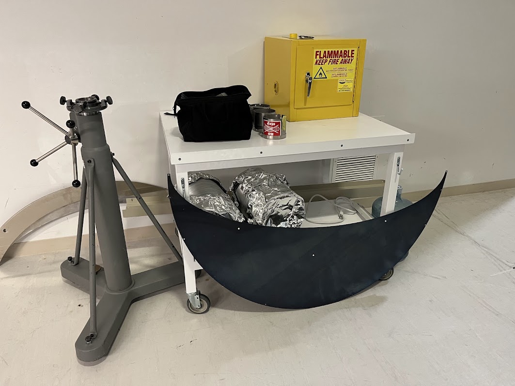
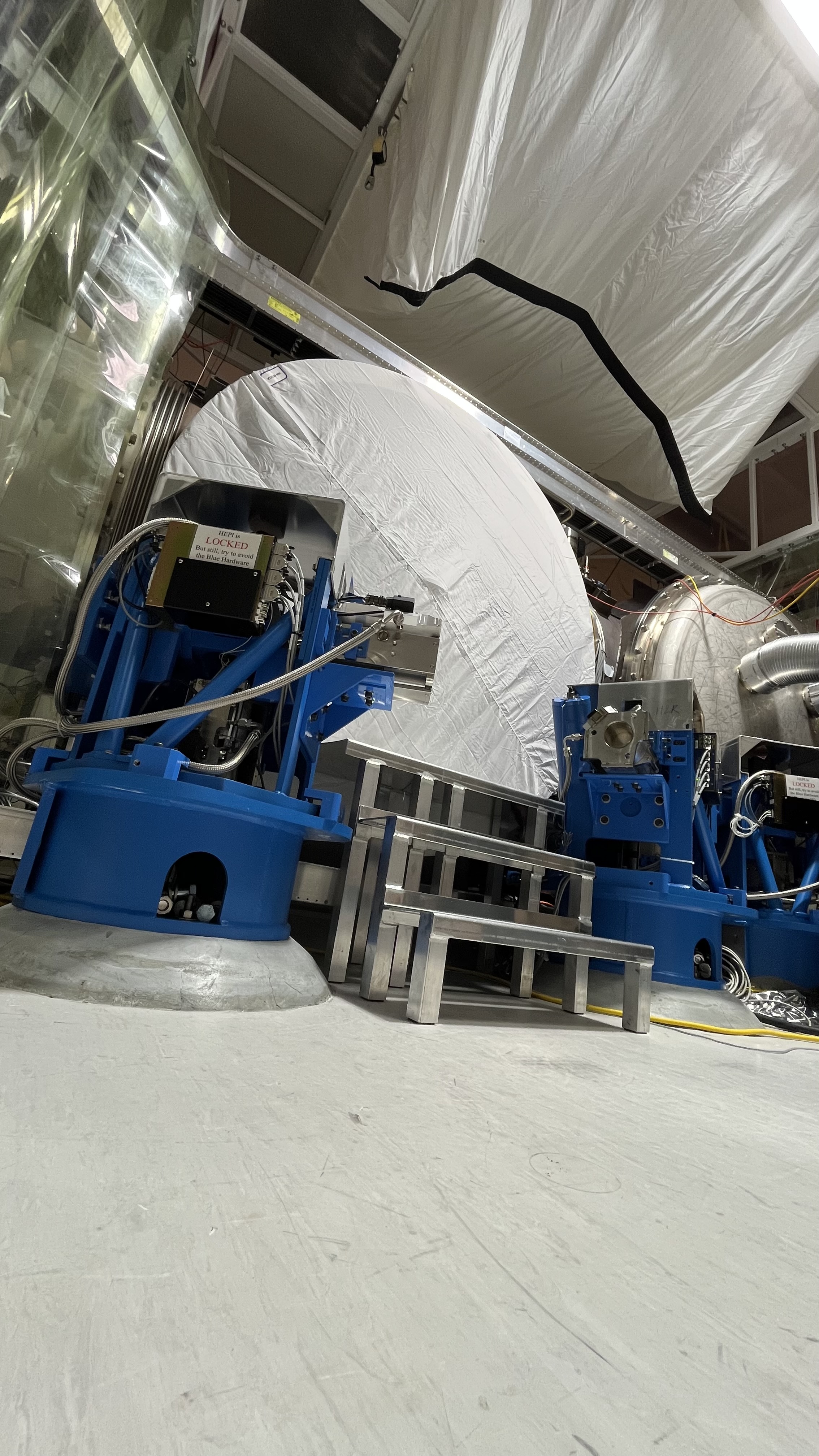
Just before lunch yesterday, vac told me doors were off HAM2. I then went out and locked the ISI and added steps to the chamber.
TITLE: 05/06 Day Shift: 1430-2330 UTC (0730-1630 PST), all times posted in UTC
STATE of H1: Planned Engineering
OUTGOING OPERATOR: None
CURRENT ENVIRONMENT:
SEI_ENV state: MAINTENANCE
Wind: 4mph Gusts, 2mph 3min avg
Primary useism: 0.18 μm/s
Secondary useism: 0.23 μm/s
QUICK SUMMARY: Currently riding out a 5.8 earthquake from the Aleutians. No new alarms, CDS overview has expected errors in: h1iopsusb2h34, h1suslo12-bbss, h1iopseib2. and h1seiproc has an IPC error.
(Jordan, Travis, Randy, Mitchell, Gerardo)
The +Y and -Y doors are off HAM2. The removal of the doors was made easy by removing most of the bolts the prior day by Travis and myself.
+ Y Door we had both O-rings get stuck to the door, we used the O-ring tools to set the O-ring back into their groove without problems. No further issues.
- Y Door had similar issues as the +Y door, when the door separated from the HAM chamber the O-rings were stuck to the door, same fix as the other door. Something to note, this door's chamber flange has lots of oxide residue on the outside of the outer O-ring, as if it was sprayed heavily with alcohol.
To be able to remove the doors for this chamber as well as HAM1, both chambers are under the same cleanroom, we need to shift the cleanroom along the Y axis to accommodate the forklift mast height when removing the doors, any door. Maybe this cleanroom should get longer legs and maybe that way keep a permanent position.
A big "thank you" to those that helped move the cleanroom.
Betsy, Ibrahim
Today we:
Madi, Camilla
Yesterday Camilla and I went down to EX to measure the return-from-vacuum ALS beam
We placed a pellicle beamsplitter between the PBS and the LPM to pick off the ALS return beam and observe its shape and size
We put the pellicle in two different locations
Multiple measurements taken at each location, photos attached. The beam was quite large, and has two bumps on the peak. It was also too bright to take an image on a CCD. Looks better than former 'mickey mouse' shape observed, but still very far from a nicely shaped beam.
TITLE: 05/05 Day Shift: 1430-2330 UTC (0730-1630 PST), all times posted in UTC
STATE of H1: Planned Engineering
INCOMING OPERATOR: None
SHIFT SUMMARY: Both doors are now off of HAM2 and the ISI is locked. The new BBS has also been delivered and is being prepped near the test stand. Baffle installation in HAM3 continueds today as well, and the TCSY table water lines started to be replaced.
LOG:
| Start Time | System | Name | Location | Lazer_Haz | Task | Time End |
|---|---|---|---|---|---|---|
| 14:54 | VAC | Jordan | LVEA | - | Checking pumps (CP1) | 15:02 |
| 15:14 | FAC | Kim | LVEA | - | Technical cleaning | 16:45 |
| 15:33 | EE | Fil | MY | - | Picking up cables | 16:03 |
| 15:40 | FAC | Randy | LVEA | - | Prep for HAM2 door removal | 16:08 |
| 16:00 | SPI | Jeff | Opt Lab | - | Part spelunking | 16:08 |
| 16:02 | IAS | Jason, Stephen | LVEA | - | BS FARO surveying | 18:59 |
| 16:08 | VAC | Gerardo, Jordan, Randy | LVEA | - | HAM2 door removal | 18:43 |
| 16:09 | PEM | Robert | LVEA | - | HAM3 baffle installation | 19:13 |
| 16:16 | IAS | Ryan C | LVEA | - | BS FARO surveying | 18:59 |
| 16:19 | CAL | Tony, Dripta | PCal Lab | - | Prepping for measurement | 16:45 |
| 16:26 | PEM | Mitchell | LVEA | - | HAM3 baffle installation | 19:25 |
| 16:46 | CAL | Tony, Dripta | EX | YES | PCal measurement | 18:49 |
| 16:50 | FAC | Chris | LVEA | - | FAMIS checks | 17:23 |
| 17:01 | EE | Fil | MER | - | BHD electronics cabling | 18:39 |
| 17:24 | FAC | Chris | Ends, Mids | - | FAMIS checks | 18:37 |
| 17:25 | FAC | Kim | LVEA | - | Technical cleaning | 18:13 |
| 17:27 | VAC | Travis | LVEA | - | HAM2 door removal | 18:44 |
| 17:37 | SUS | Betsy, Ibrahim | LVEA | - | Many tasks (Betsy out @ 18:22) | 18:37 |
| 18:13 | FAC | Kim | FCES | - | Technical cleaning | 18:59 |
| 18:23 | SUS | Betsy | EX | - | Looking for ergo arm part | 19:06 |
| 18:43 | SEI | Jim | LVEA | - | Locking HAM2 ISI | 19:06 |
| 19:18 | FAC | Randy | LVEA | - | Craning in West bay | 20:03 |
| 20:14 | VAC | Jordan | LVEA | - | HAM6 RGA | 20:23 |
| 20:15 | FAC | Randy | LVEA | - | Moving scaffolding, BBS staging | 22:13 |
| 20:15 | SUS | Betsy | LVEA | - | BBS staging | Ongoing |
| 20:19 | IAS | Jason, Ryan C, Stephen | LVEA | - | BS FARO surveying | Ongoing |
| 20:33 | SUS | Ibrahim | LVEA | - | BBS staging | Ongoing |
| 20:36 | SAF | Richard | LVEA | - | Checks | 21:09 |
| 20:39 | CAL | Tony | PCal Lab | - | Checking part number | 21:30 |
| 20:52 | SEI | Jim | LVEA | - | HAM3 table masses | 22:37 |
| 20:59 | TCS | TJ, Camilla, Madi | LVEA | - | TCSY table water lines | 23:30 |
| 22:07 | SUS | Tom | LVEA | - | Delivering cables | 22:13 |
| 22:10 | VAC | Jordan | LVEA | - | HAM6 RGA | 22:18 |
| 22:47 | SLIC | Robert | LVEA | - | HAM3 baffle installation | Ongoing |
| 22:55 | VAC | Jordan, Gerardo | LVEA | - | Bringing pump to CP1 | 23:50 |
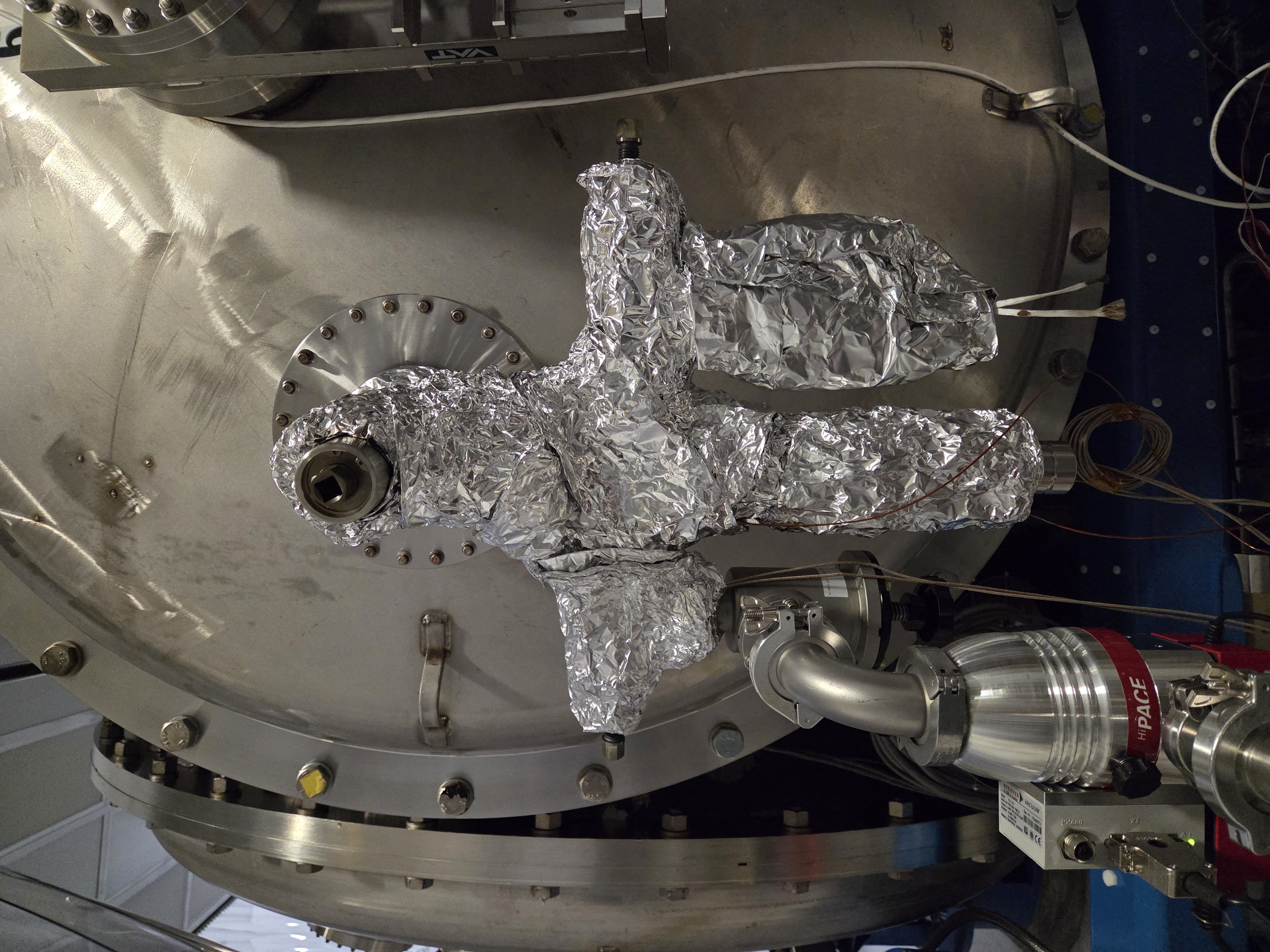
The HAM6 RGA tree had a known leak coming from the needle valve on the calibrated leak, so the calibrated leaks were removed from the system and the tree now only consists of the RGA, 10 l/s Ion Pump and a pump out port.
The tree was re-wrapped with heat tape and is currently baking at high temp using an aux cart and 80 l/s turbopump. Caution tape has been installed around the -Y door of HAM6, please avoid the area.
WP13221 Add BBSS Fast Channels to DAQ
Tom, Oli, Erik, Dave:
18 BBSS_OSEMINF (SUM, X, Y) DQ channels were added to the DAQ, all at 256Hz. DAQ retstart was required.
WP13223 Add PT100A VACSTAT slow channels to DAQ
Dave:
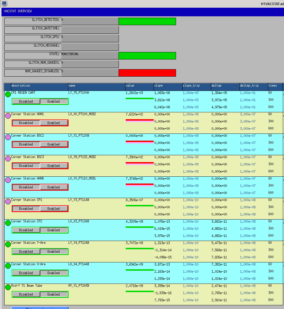
A new H1EPICS_VACSTAT.ini was generated adding PT100A. An EDC+DAQ restart was required.
WP13228 Add FW2 slow channels to DAQ
Erik, Jonathan, Dave:
Puppet was changed to add three channels unique to FW2 (STATE_0, STATE_1, NUM_WRITERS). An EDC+DAQ restart was required.
WP13235 h1sush6 IO Chassis Install
Fil, Dave:
Fil moved the IO Chassis for h1sush6 from its temporary location in an adjacent rack into the SUSH6 rack on the MER. h1sush6 front end was powered down for the duration of this work.
DAQ Restart
Erik, Jonathan, Dave:
The DAQ and EDC were restarted.
FW2 stopped at the time puppet was upgraded due to a file creation race condition.
For the DAQ restart itself, the main issue was two spontaneous restarts of FW1, both after running for 10 minutes but not synced to the writing of the second trend frame files.
11:23:13 h1susb2h34 h1suslo12 <<< New model, add DQ chans to DAQ
11:26:44 h1daqgds0 [DAQ] <<< 0-leg restart, susl012, vacstat, fw2 additions
11:26:48 h1daqfw0 [DAQ]
11:26:48 h1daqtw0 [DAQ]
11:26:49 h1daqnds0 [DAQ]
11:27:39 h1susauxb13 h1edc[DAQ] <<< EDC for vacstat, fw2
11:30:49 h1daqdc1 [DAQ] <<< 1-leg restart
11:30:58 h1daqfw1 [DAQ]
11:31:00 h1daqtw1 [DAQ]
11:31:03 h1daqnds1 [DAQ]
11:31:11 h1daqgds1 [DAQ]
11:32:13 h1daqgds1 [DAQ] <<< gds1 needed a restart
11:40:28 h1sush6 ***REBOOT*** <<< Power up after IO Chassis work
11:41:23 h1daqfw1 [DAQ] <<< First FW1 spontaneous restart, suspiciously close to start of sush6
11:41:30 h1sush6 h1iopsush6
11:41:43 h1sush6 h1susom0
11:41:56 h1sush6 h1susobs
11:42:09 h1sush6 h1susam
11:42:22 h1sush6 h1susomcab
11:42:35 h1sush6 h1susom1ab
11:42:48 h1sush6 h1susom2ab
11:43:01 h1sush6 h1susom3ab
11:51:41 h1daqfw1 [DAQ] <<< Second FW1 spontaneous restart, roughly +10mins
12:02:32 h1daqfw1 [DAQ] <<< Third FW1 spontaneous restart, again roughly +10mins
WP 13235
WP 13169
Drawing O5 SUS HAM6 (sush6) System Wiring Diagrams - D2300379
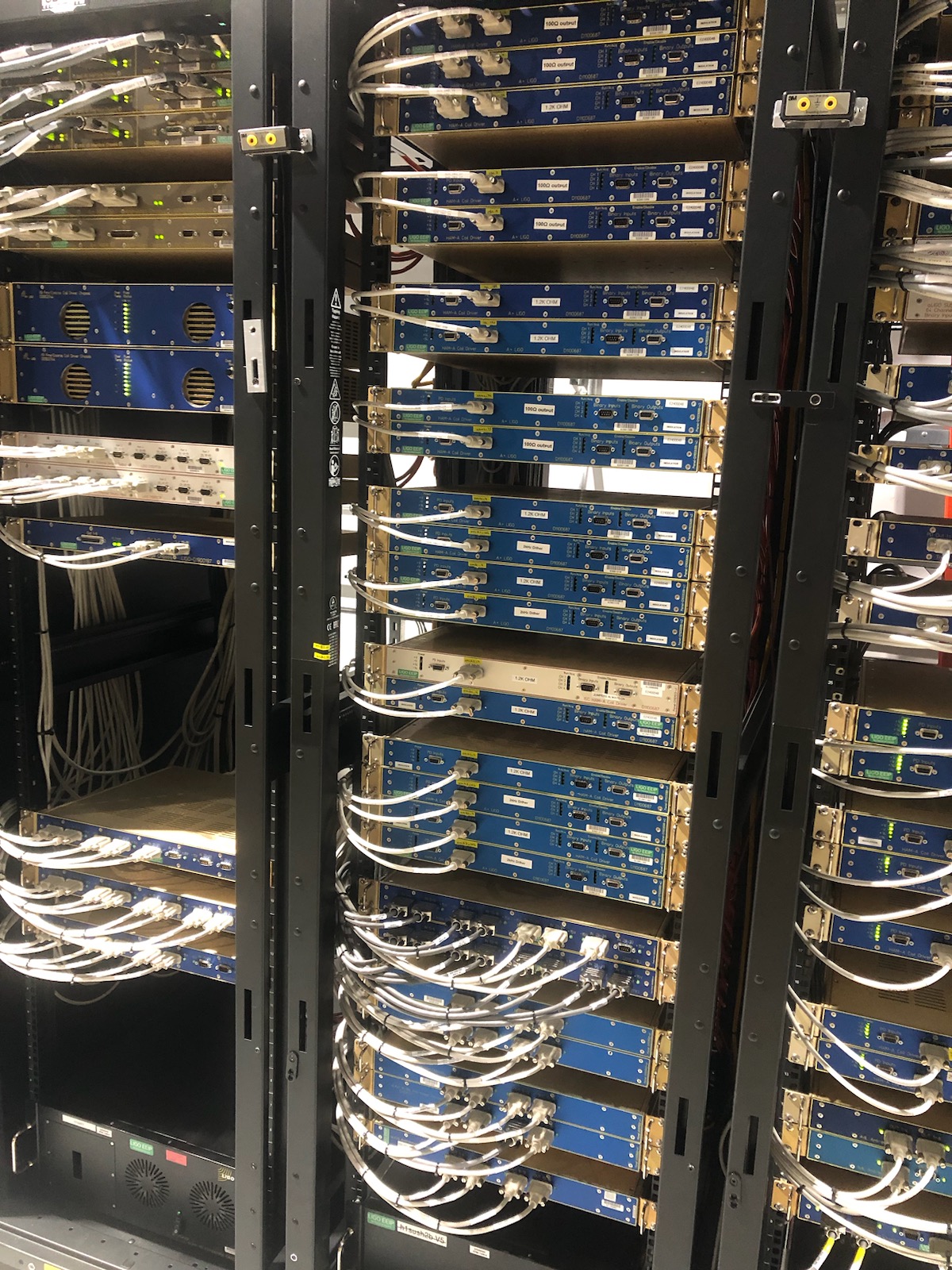
The O5 SUS HAM6 electronics and in-rack cabling installation in the MER is complete. System wiring diagrams D2300379 will need to be updated to show no IO h1susauxh6 was installed. New ADC cards (SUS AUX) were installed in the h1seih7 IO chassis.
IO chassis h1sush6 and h1sush7 share a 24V power supply. A dual Kepco power supply was installed to power the ±18V for SUS-M2. New electronics except the h1sush6 IO chassis were left powered off.
Status of the SUS-R7 rack is ongoing. All electronics installed. All long cables from MER and CER pulled and dressed. Rack requires ±18V and 200V for PSAMS. Depending on loads, plan is to use the SUS-R4 power supplies for the ±18V. The HV power supply will need to be placed on the HAM6 vacuum gauge interlock.
Fil, Erik, Dave:
we have powered down h1sush6 front end in preparation for Fil's move of the IO Chassis into the SUSH6 rack on the MER. Reminder that this front end is not connected to the Dolphin switch, so there is no risk of a corner station Dolphin glitch.
Gerardo, Jordan, Jonathan, Dave:
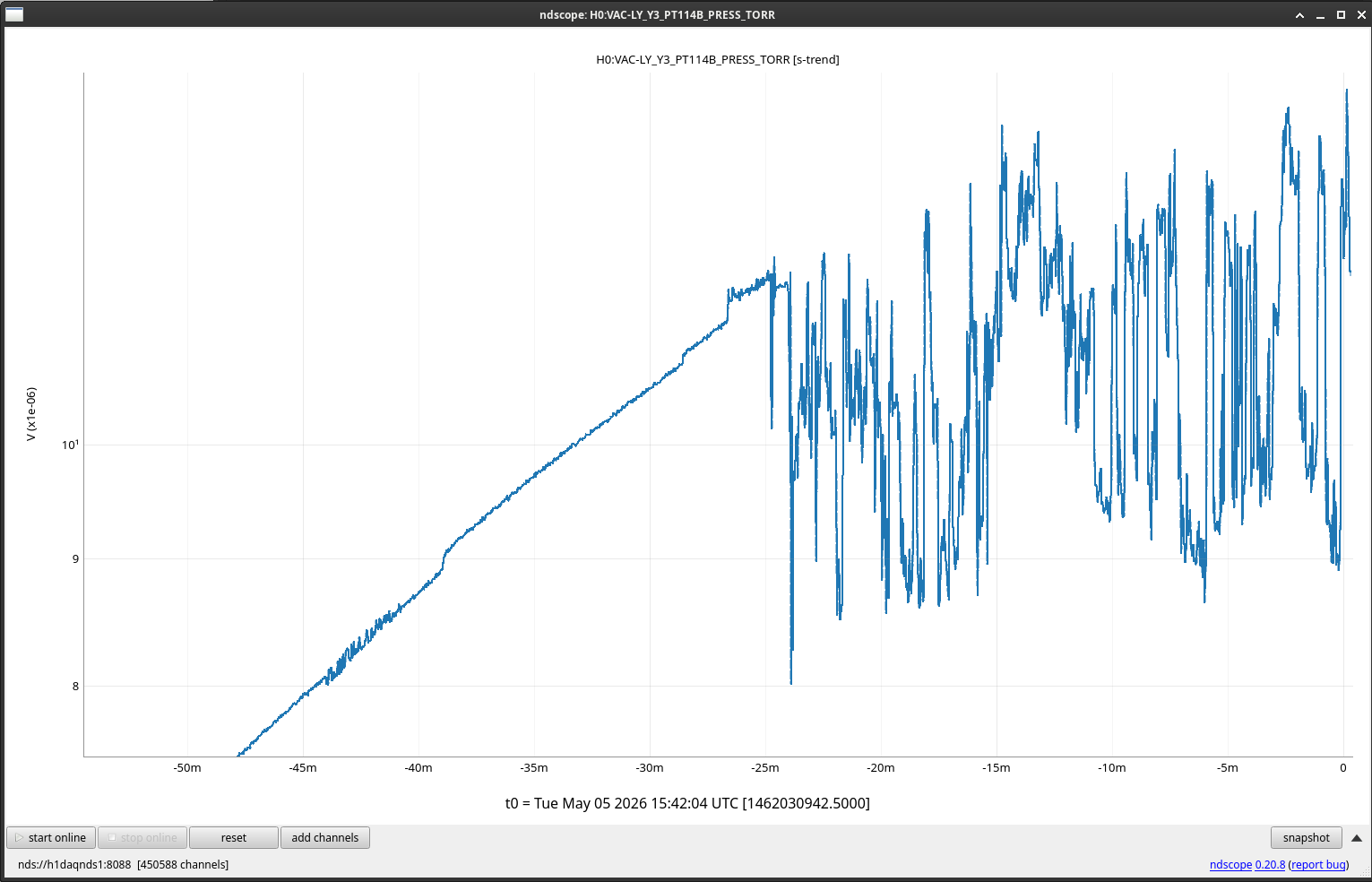
PT114 has started to rise rapidly. At 16:50 I changed its alarm high from 2.0e-08 to 5.0e-04.
Later PT114B's VACSTAT continued to trip due to the large delta-P. After clearing the alarms I have disabled PT114B in VACSTAT (but its level alarms remain active).
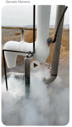
As mentioned by Gerardo CP1's outside discharge line pipe is now completely free of ice (Nov 2025 image added for comparison).
The pressure at PT114 has continued to rise this morning and mostly leveled out, but it's bouncing around the channel's low-level alarm threshold at 1e-5 Torr. This is triggering Verbal Alarms and the CR alarm handler computer every time the pressure goes above 1e-5 Torr, which is on average a few times per minute.
I've commented out PT114 from the Verbal Alarms vacuum channel list to reduce redundant alarms and will look into modifying the thresholds somehow for the alarm handler.
[Tom Roocke, Oli]
Summary: The 6 QOSEMs and their signal chain for the BBSS are operational with the final sat amp, CER wiring, CDS mapping, in vac DB25 extension cables. All that remains to test before SUS installation is the duopus cables, which are in C&B currently.
In continuation from yesterday, we are testing out the QOSEM signal chain prior to installation of the BBSS. Yesterday we verified the sat amp was still functional and the readouts were showing up in CDS appropriately. See LHO:90072. Today we checked both the DB25 to DB25 extension cables, and the QOSEMs. To come is testing of the duopus cables, which are still in C&B.
DB25 Extension Testing:
Using a known functional Duopus cable (S2600215), and inair DB25, we tested the three DB25 extension cables by reading for the QOSEM coil resistance and diode drops at the in air DB25, where it connects to the sat amp. See the signal continuity test section in T2600170 for more information on this. All 3 cables are functional.
S2001548: DB25 working
S2100358: DB25 working
S2100410: DB25 working
QOSEM CDS Readout Testing:
Using a known functional Duopus Cable (S2600215), DB25 Extension (S2100410) and in air DB25, we checked for the open sum voltage in the CDS readout. This is the voltage seen on the sum channel of the QPD with no lens installed. Seeing a nonzero voltage here indicates that the QOSEM LED, QPD and signal chain are functional, but will be far lower than the operational sum level when the lens flag is appropriately focusing light onto the QPD. We tested the open sum voltage for all 6 QOSEMs designated for the BBSS. All QOSEMs and there signal chain are functional.
S2600008: working with open sum of 13910
S2600009: working with open sum of 14755
S2600010: working with open sum of 15550
S2600011: working with open sum of 15470
S2600012: working with open sum of 15348
S2600013: working with Open Sum of 14380
Today the QOSEM Duopus cable finished C&B, so I unbagged and tested them in the triples lab. I checked for continuty and any shorted pins with a multimeter, and all 4 cables passed. With this all parts of the QOSEM signal chain have been tested and ready to go for on suspension testing