louis.dartez@LIGO.ORG - posted 01:05, Wednesday 13 December 2023 - last comment - 09:04, Wednesday 13 December 2023(74771)
Follow up to LHO DARM modeling efforts
Gabriele, Sheila, Artem, Louis
Since Gabriele found low frequency noise (~4 Hz) non-linearly coupling into DARM at higher frequencies (~15-25 Hz) (see LHO:73937), Sheila & I have been working to prop up a dependable model of the DARM loop that can be used to estimate stability margins and offload actuation from ETMX L3 to L2 and L1. N.B. we're not 100% certain that the noise we're chasing is due to the ETMX ESD.
1. The DARM Model
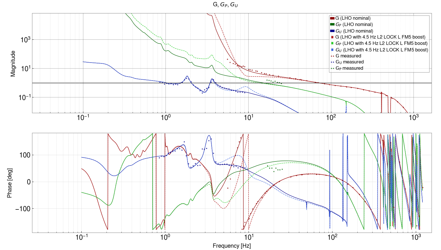
To estimate DARM loop stability, we've been primarily looking at modeling and directly measuring IN1/IN2 at the input to each stage's LOCK bank filter. IN1/IN2 at the input to the L3 LOCK bank filter (often measured as (IN1/EXC)/(IN2/EXC) so as to not be biased towards 1) is the open loop gain, G, of the DARM loop. We've been calling IN1/IN2 measured at the input to the L2 and L3 LOCK banks Gp and Gu, respectively. This is because they each behave somewhat like an effective open loop gain as measured at those points in the offloaded DARM loop. Similar to G, Gp, and Gu (the "OLGs"), we calculate the loop suppression, 1/(1-G), and the closed loop gain, G/(1-G), for each our three test points (G, Gp, and Gu) at the input of each ETMX LOCK bank filter.
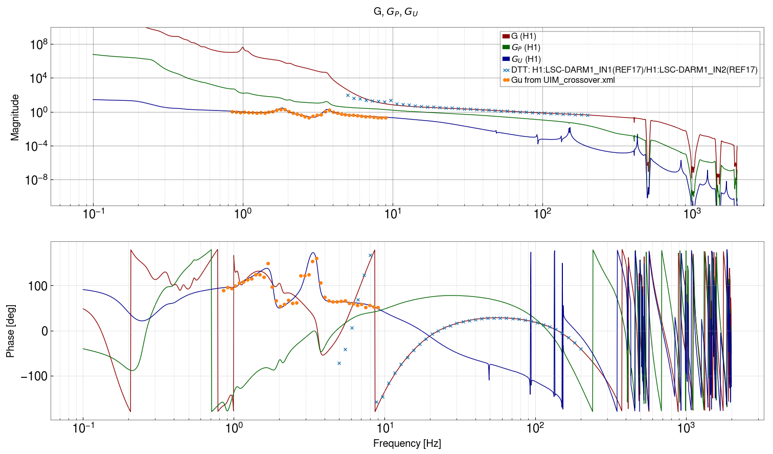
Figure 1 above is a Bode plot of G, Gp, and Gu for the LHO DARM loop overlaid with measurements taken for G and Gu. The OLG, G, measurement was taken from a recent calibration swept sine and the measurement of Gu is courtesy of Sheila from LHO:74226. The two measurements shown for G and Gu match the model pretty well. There is some noise in the Gu measurement but the structure is in pretty good agreement between the model and the data. The measurement of G also matches pretty well but begins to deviate below 10 Hz. This is likely in large part due to error in fitting the sensing function, C, at low frequencies. It's worth noting that the UIM stage has multiple UGFs just below 2 Hz and 4 Hz; this is okay but not ideal.
We tried taking a measurement of Gp but we've been unable to get good agreement between the current DARM loop model and these measurements (this is mentioned in LHO:74264). We've only tried relatively low coherence measurements so far in this current sprint so we plan to get some better measurements of this soon to compare against the model. However, it's worth noting that the PUM has been a bear to model properly for a while (see for example the PUM discussion in LHO:63450). A few years ago Jenne successfully modeled length-to-pitch-to-length cross-coupling that matched data taken at the PUM stage (LHO:48738). In light of the recent modeling push, Sheila and I are have begun working to follow up on this work to include yaw in the hopes of modeling and suppressing this effect from coupling to DARM. More on that later as our current major goal is to reduce ETMX actuation as introduced at the top.
The Gu points in Figure 1 were calculated from a measurement of IN1/EXC at the input of the L2 stage LOCK bank filter. Direct measurement of Gu = IN1/IN2 was difficult due to low coherence. The relationship between Gu and IN1/IN2 is Gu = (IN1/EXC)/(1+(IN1/EXC)). See Section 4 of DCC:LIGO-T2300436 for a discussion on that relationship.
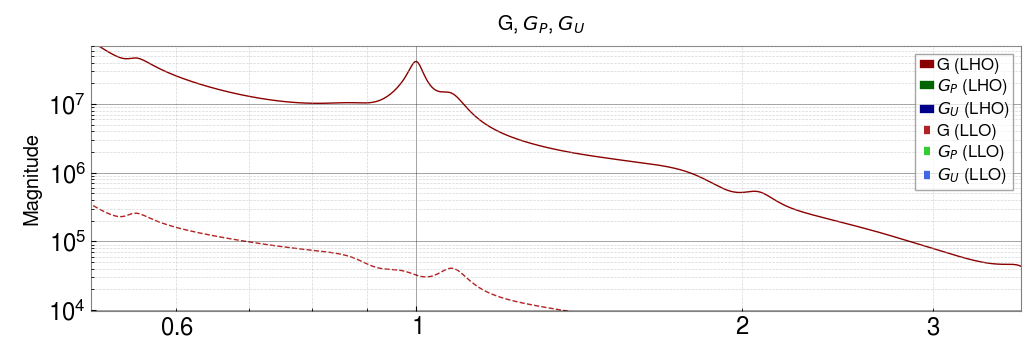
2. Comparison of LHO and LLO DARM Models
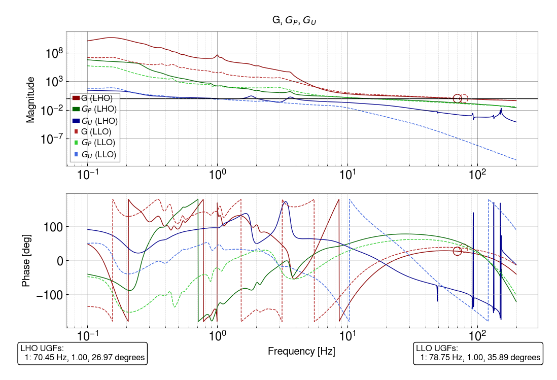
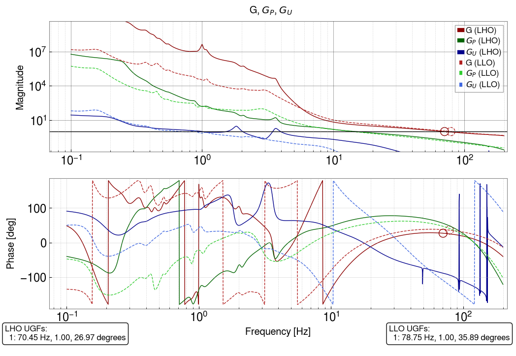
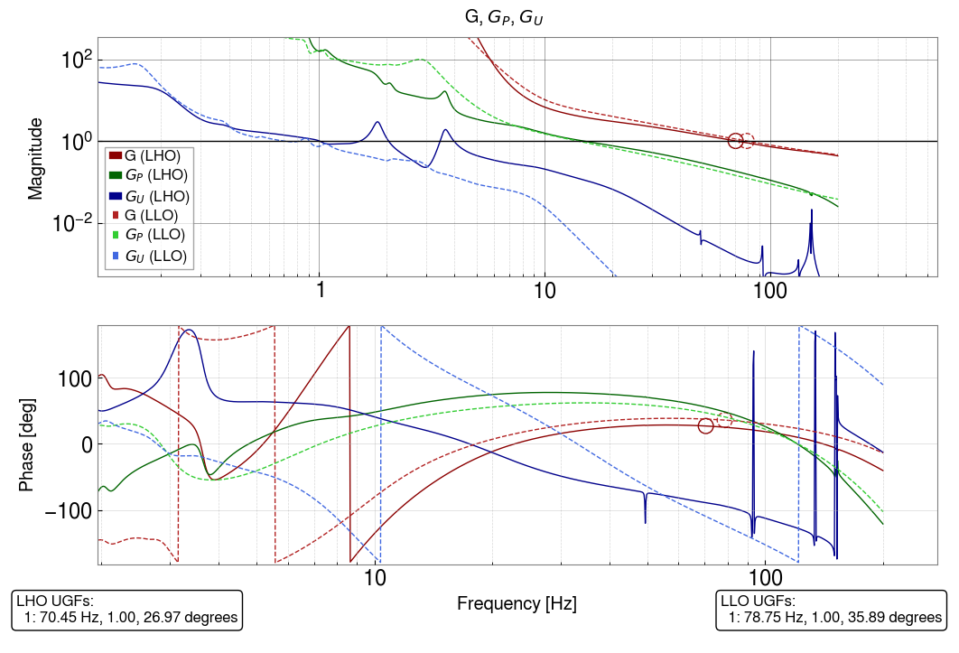
Here is a quick comparison of recent DARM loop models for LHO and LLO.
For searching purposes I'm writing their modeled OLG UGFs:
LHO UGFs:
1: 70.45 Hz, 26.97 degrees
LLO UGFs:
1: 78.75 Hz, 35.89 degrees
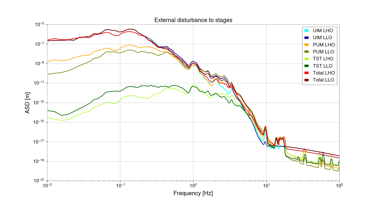
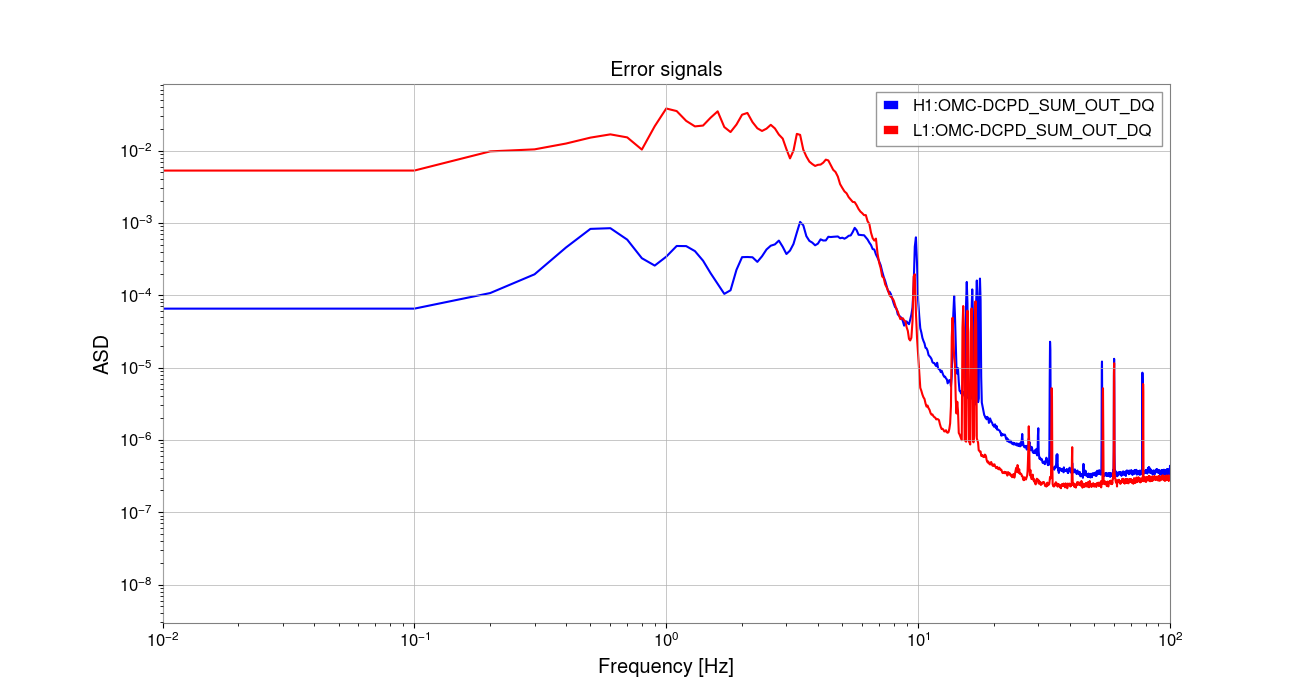
The DARM OLG magnitudes between LLO and LHO differ at low frequencies by roughly 3 orders of magnitude near 1Hz. Here's an even higher zoom near 1Hz: LHO_LLO_comparison_OLG_super_zoom_low_freq.png. As an independent check into whether that makes sense, Artem pulled up the external disturbance sent to each actuation stage at both sites using CAL-DELTAL_CTRL_{UIM,PUM,TST}_DBL_DQ and saw that they're similar between LLO and LHO (direct link to this plot). Then he looked at the LHO and LLO error signals and found a discrepancy of 2 orders of magnitude in the expected direction (direct link to this plot). So that all seems to roughly track, which is great news. See LHO:74744 for Artem's discussion.
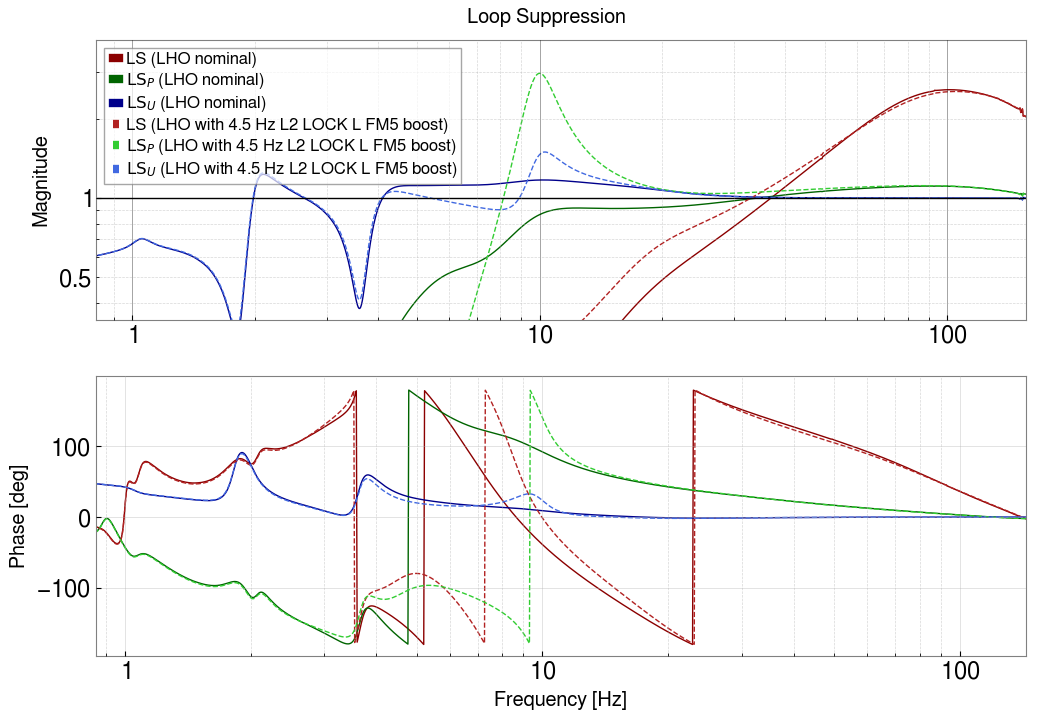
3. Instability of 4.5Hz boost filter not predicted by DARM model
In LHO:74226, Sheila tried engaging a L2 LOCKL FM2, "boost4.5", which caused a lockloss. She successfully engaged the boost without a lockloss the day before just before the Tuesday maintenance period.
Here is a comparison of the LHO model with and without this boost engaged.
The hope was that we would look at the model with the boost included and be able to confirm that the resultant loop configuration is unstable. However, we aren't able to point to anything that obviously indicates that that's the case. The corresponding loop suppression plot shows some peaking near 10Hz but nothing that would have us consider it a smoking gun.
=====
So the DARM modeling efforts are progressing but there is still much to do..
Images attached to this report
Comments related to this report
louis.dartez@LIGO.ORG - 09:04, Wednesday 13 December 2023 (74780)
after discussing a bit with Gabriele this morning and taking a closer look at the scenario with the 4.5Hz boost applied, I think I was too quick to suggest that the instability disagrees with the model.

1. There is some minor gain peaking the TST stage near 10Hz with the boost applied compared to the nominal state.
2. Gp inches closer to unity at 10Hz. Given that we already don't trust the Gp model right now, this could put us close enough to unity to cause issues at 10Hz, which is also where the phase goes to 0.
3. OLG also starts to dip to unity near 10Hz.

all this together may actually suggest that the loop with the 4.5Hz boost engaged, or the transition from the nominal state to the new state with the boost engaged, could be unstable. So perhaps Sheila's experience with having the boost be fine one day and cause a lockloss the next day is consistent with the model afterall.
anthony.sanchez@LIGO.ORG - posted 00:05, Wednesday 13 December 2023 (74773)
Tuesday EVE End Shift
TITLE: 12/13 Eve Shift: 00:00-08:00 UTC (16:00-00:00 PST), all times posted in UTC STATE of H1: Observing at 158Mpc INCOMING OPERATOR: TJ SHIFT SUMMARY:
00:27 UTC HWS was restarted and took us out of Observing by making SF changes for a minute. The HWS Engineer making the changes was still in the control room and managed to handle the SDF changes which allowed us to get back to Observing. See Alog : https://alog.ligo-wa.caltech.edu/aLOG/index.php?callRep=74770
00:29 UTC OBSERVING was reached again.
After this a small earthquake rolled through which we survived, but otherwise the night was quite.
Everthing went smooth like butter.
anthony.sanchez@LIGO.ORG - posted 16:11, Tuesday 12 December 2023 (74768)
Tuesday EVE Shift Start
TITLE: 12/13 Day Shift: 16:00-00:00 UTC (08:00-16:00 PST), all times posted in UTC STATE of H1: Observing at 156Mpc OUTGOING OPERATOR: Corey CURRENT ENVIRONMENT:
SEI_ENV state: CALM
Wind: 5mph Gusts, 3mph 5min avg
Primary useism: 0.02 μm/s
Secondary useism: 0.33 μm/s QUICK SUMMARY:
H1 Is locked at NOMINAL_LOW_NOISE and OBSERVING for the past hour.
Violins lookin great!
ryan.short@LIGO.ORG - posted 16:04, Tuesday 12 December 2023 (74765)
Ops Day Shift Summary
TITLE: 12/12 Day Shift: 16:00-00:00 UTC (08:00-16:00 PST), all times posted in UTC STATE of H1: Preventive Maintenance INCOMING OPERATOR: Tony SHIFT SUMMARY: Relatively light maintenance day followed by some trouble getting locked, but after adjusting thresholds in ALS Guardians, was able to lock without much issue.
16:07 Lockloss from commissioning test, ISC_LOCK to IDLE
thomas.shaffer@LIGO.ORG - posted 15:34, Tuesday 12 December 2023 (74766)
ALS green transmission threshold lowered
Ryan S, Jenne D, Sheila
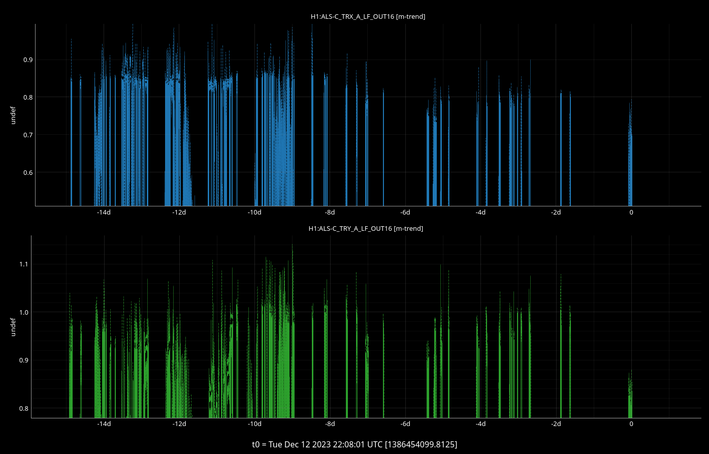
The ALS_COMM and DIFF nodes will check on the green arm transmission when finding IR to ensure that the arms are aligned well enough to move on. This threshold has been set to 0.75 but I lowered it to 0.65 since we've ran into this threshold as few times in the last week and have been unable to improve the arm transmission.
Last week this happened on Thursday (alog74655) and I just manualed around the state to continue locking. It worked for that lock to get us back up, and then it wasn't a problem with future locks until today. Today, the arm transmission was low for both arms so we went to confirm that there was no PR3 movement, and then we restored optics back to the start of the previous lock. This also didn't help. Looking at the arm power over the last few weeks (attachment 1), after the PR3 and table work from last Tuesday (alog74618) it has been lower than before then but as low as we were seeing today. The current thinking is that the PR3 move last week brought our powers lower, and while the table work improved the COMM beatnote, it did nothing for the arm powers. Once the IFO gets to a better full lock alignment, this alignment tends to give us better ALS power next lock acquisition, so lowering this threshold should help us get to that point and hopefully help sequential locks.
The long term solution would be to go back on table to realign the rest of the COMM path to camera, then renormalize the arm powers so that 1 is actually our max power, then bring this threshold back to the 0.75 that it was*. Going on that table always carries rick of making things worse, so we definitely don't want to be doing this right before the holidays. We will reconvene in 2024 on this issue if it's still an issue.
*There's a comment in the guardian code that it was 0.85 from Aug 12, 2020.
jordan.vanosky@LIGO.ORG - posted 13:36, Tuesday 12 December 2023 (74763)
Functionality Test Performed on EX/MX Turbo Pumps
Jordan, Janos
We ran the functionality test on the main turbopumps in MX and EX during Tuesday Maintenance (12/12/23). The scroll pump is started to take pressure down to low 10^-02 Torr, at which time the turbo pump is started, the system reaches low 10^-08 Torr after a few minutes, then the turbo pump system is left ON for about 1 hour, after the hour the system goes through a shut down sequence.
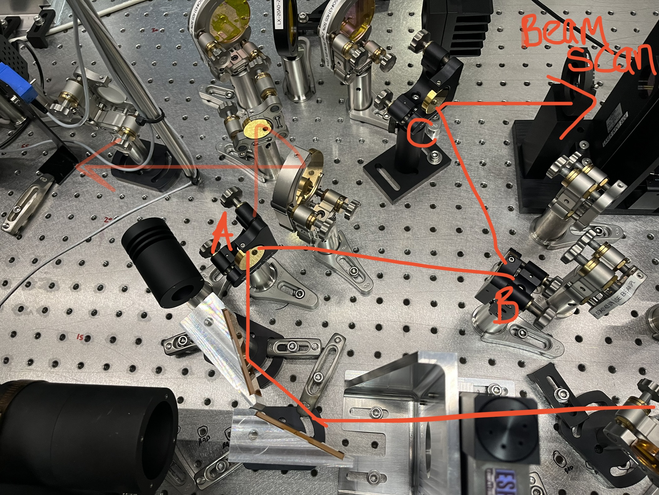
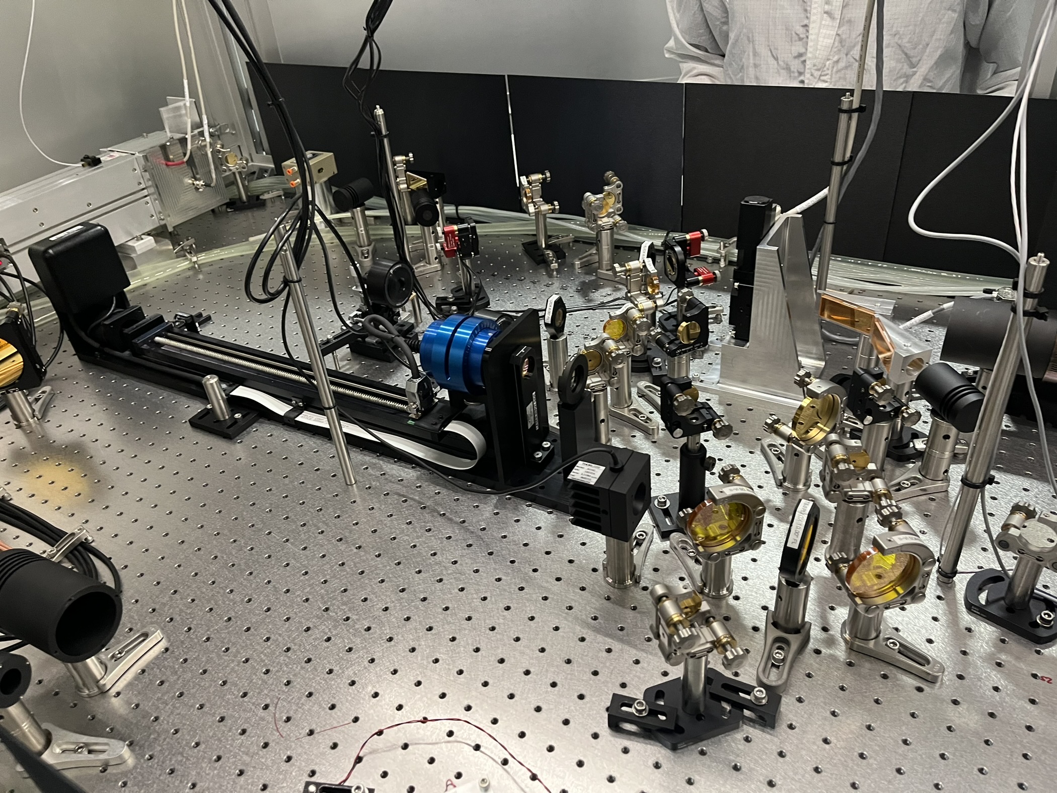
We borrowed the Ophir PH00235 USB MSP-NS-Pyro 9/5 bean scanner from CIT. It has a PH00092 removable 7.5" FL lens on the front and is on a 500mm rail. WE checked the scanner and rail worked in the lab using our Nanoscan laptop and the Nanoscan v1 software.
On CO2X (layout T1200007) we added three Gold coated steering mirrors just after the power control waveplate. Added a beam block panel on the back of the table. While aligning we kept ther CO2 power requested at 0.1W. Started aligning the beam to the beamscan but didn't finish before the end of maintenance.
We left the beanscan and the three mirrors on the table, we moved the mirror that was in the path ("A" on photo) out of the path. Plan to finish aligning and take data next Tuesday. The cables and driver boxes are in a tote labeled "nanoscan" in the TCS cabinet and the laptop is back in the optics lab cabinet. Photos of table and beampath (nominal lighter red) attached.
david.barker@LIGO.ORG - posted 11:01, Tuesday 12 December 2023 - last comment - 13:17, Wednesday 13 December 2023(74755)
WP11568 TW0 raw minute trends offload
As the first part of the TW0 raw minute trend file offload, tw0 is now writing to a new area freeing up the old files for transfer.
nds0 was restarted at 10:44 PST to serve the past 6 months of data from their temporary location as the files are being transferred to h1daqframes-0. The file copy takes about 30 hours.
Comments related to this report
david.barker@LIGO.ORG - 16:22, Tuesday 12 December 2023 (74769)
camilla.compton@LIGO.ORG - posted 08:26, Tuesday 12 December 2023 - last comment - 13:12, Wednesday 13 December 2023(74750)
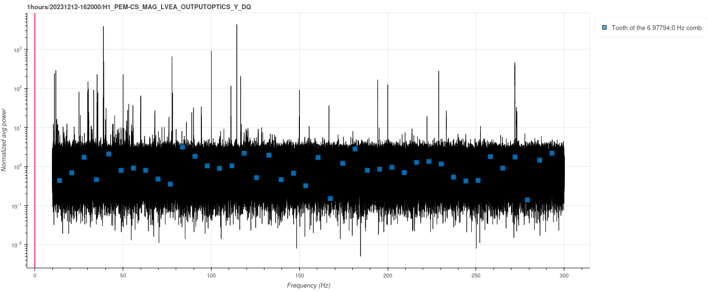
ITM HWS Camera's Powered off at 16:15UTC, search for cause of DARM Comb
This morning at 8:15am (16:15UTC) I turned off the external power supply that powered both ITM HWS CCD cameras (Dalsa 1M60), located on the floor under the HWS table. We'll plan to check the magnetometer data to see if the 74738 comb is still present.
After we stopped HWS code and remotely turned off camera's in 74738, the DARM comb still remained. Dan, Daniel, Nutsinee expect this could be the framegrabber in the HWS computer still sending a 7Hz signal. We can troubleshoot this and how the camera's are grounded to the optics table later.
Comments related to this report
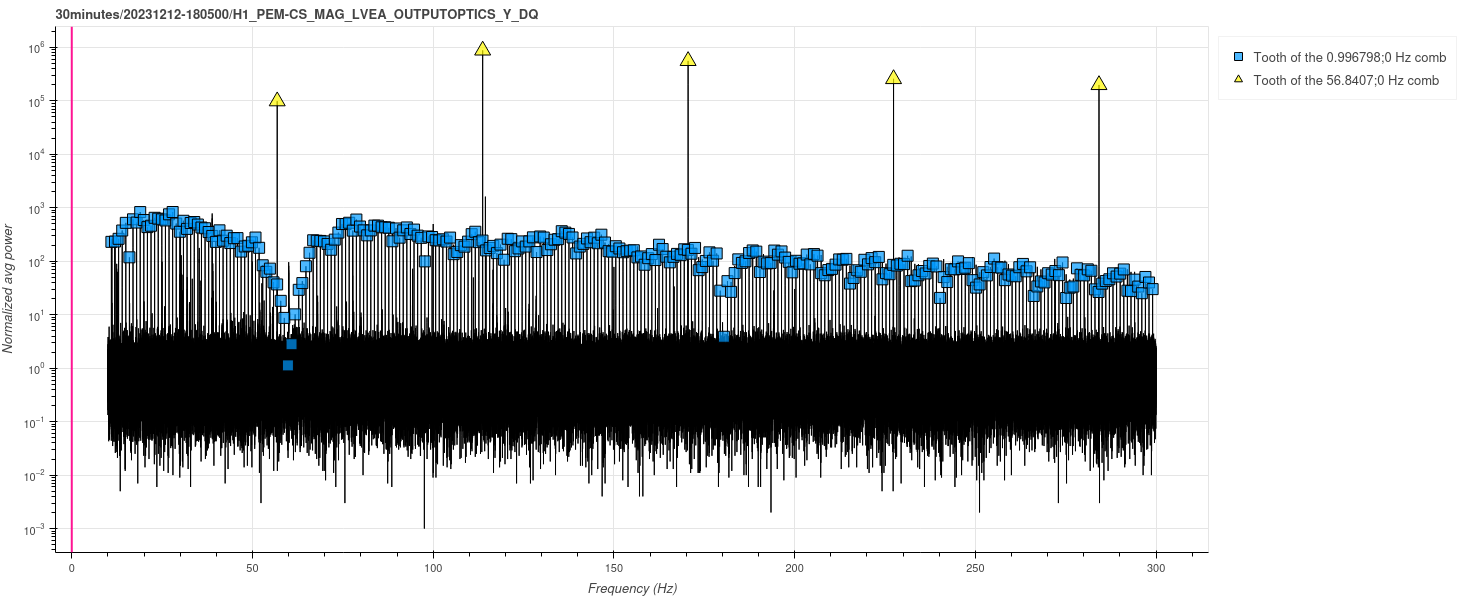
ansel.neunzert@LIGO.ORG - 09:29, Tuesday 12 December 2023 (74752)
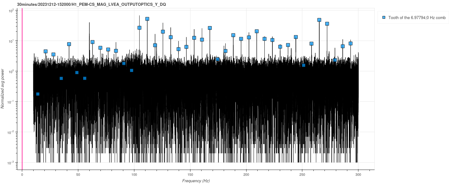
Camilla says the camera was turned on but not initialized at 10:03 Pacific / 18:03 UTC. Took a 30m spectrum starting 18:05 utc, attached. There is a strong near-1Hz comb and a strong near-57 Hz comb.
Images attached to this comment
camilla.compton@LIGO.ORG - 12:44, Tuesday 12 December 2023 (74759)
At 20:40UTC (12:40PT) we powered off both ITM computers h1hwsmsr and h1hwsmsr1. Dave has been notified. In 30 minutes we can try power cycling the cameras to see if the computers are off whether they re-initalize causing a comb.
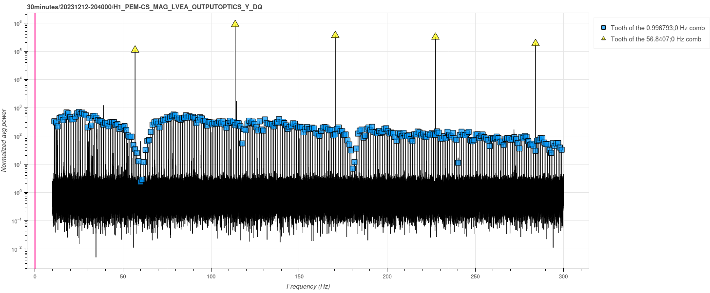
ansel.neunzert@LIGO.ORG - 13:34, Tuesday 12 December 2023 (74762)
Combs are still there with ITM computers off. Looks pretty much identical to the previous spectrum (very tiny frequency shift in the near-1Hz comb, though).
Images attached to this comment
camilla.compton@LIGO.ORG - 13:44, Tuesday 12 December 2023 (74764)
At 21:30UTC Erik unplugged the fiber connections that run from the back of the computers to the HWS cameras. Computers still off.
At 21:37UTC I power cycled the external supply to the cameras, to test if the cameras still turn on with a comb with no computer/frame grabber connection.
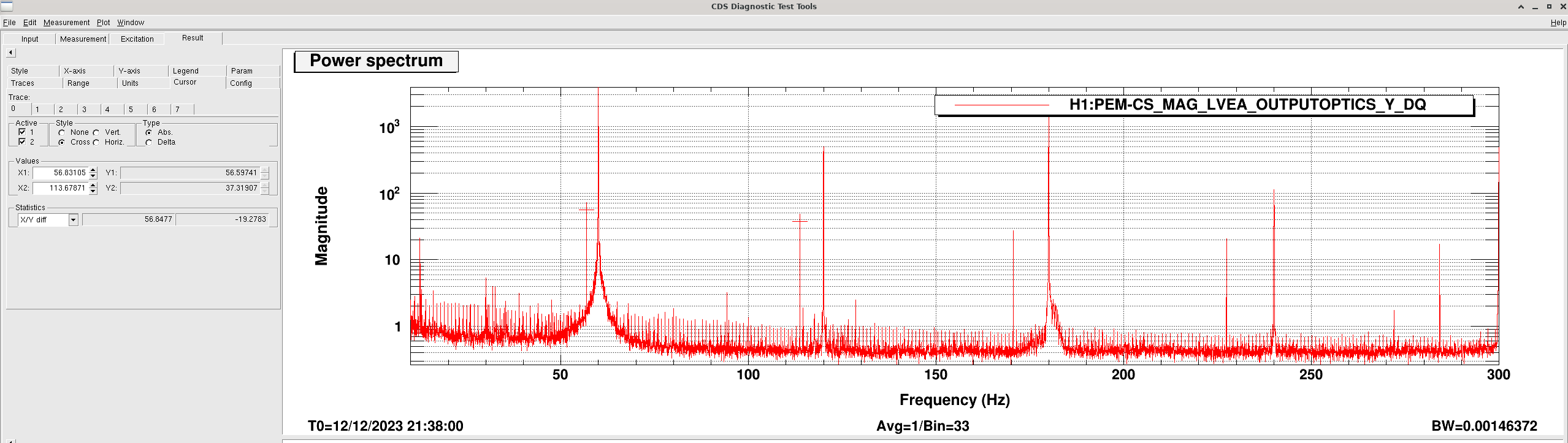
camilla.compton@LIGO.ORG - 16:37, Tuesday 12 December 2023 (74770)
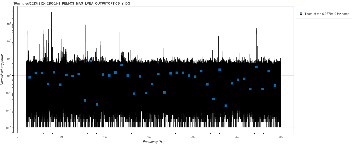
When the camera's restanted with the fiber link to the computers disconneted, we again saw the 1Hz and 57Hz combs, plot attached. It appears default for ITMX is 57Hz and ITMY is 1Hz. We should check if the camera software allows us to to put these to zero/ off.
For now we've replugged in the fiber connections, turned on the computers and restarted the hws code, both at 7Hz (this created some sdf diffs from the H1:TCS-ITMY_HWS_{}_POS_{X,Y} channels restarting with default values that kicked us out of observing, sorry)
Lasers still off, will turn lasers on tomorrow during commissioning to avoid sdf diffs.
Images attached to this comment
camilla.compton@LIGO.ORG - 13:12, Wednesday 13 December 2023 (74785)
vladimir.bossilkov@LIGO.ORG - posted 08:29, Friday 28 July 2023 - last comment - 12:31, Tuesday 12 December 2023(71787)
H1 Systematic Uncertainty Patch due to misapplication of calibration model in GDS
First observed as a persistent mis-calibration in systematic error monitoring Pcal lines which measure PCAL / GDS-CALIB_STRAIN affecting both LLO and LHO, [LLO Link] [LHO Link], characterised by these measurements consistently disagreeing with the uncertainty envelope.
It us presently understood that this arises from bugs in the code producing the GDS FIR filters there exists a sizeable discrepancy, which Joseph Betzwieser is spear-heading a thorough investigation to correct,
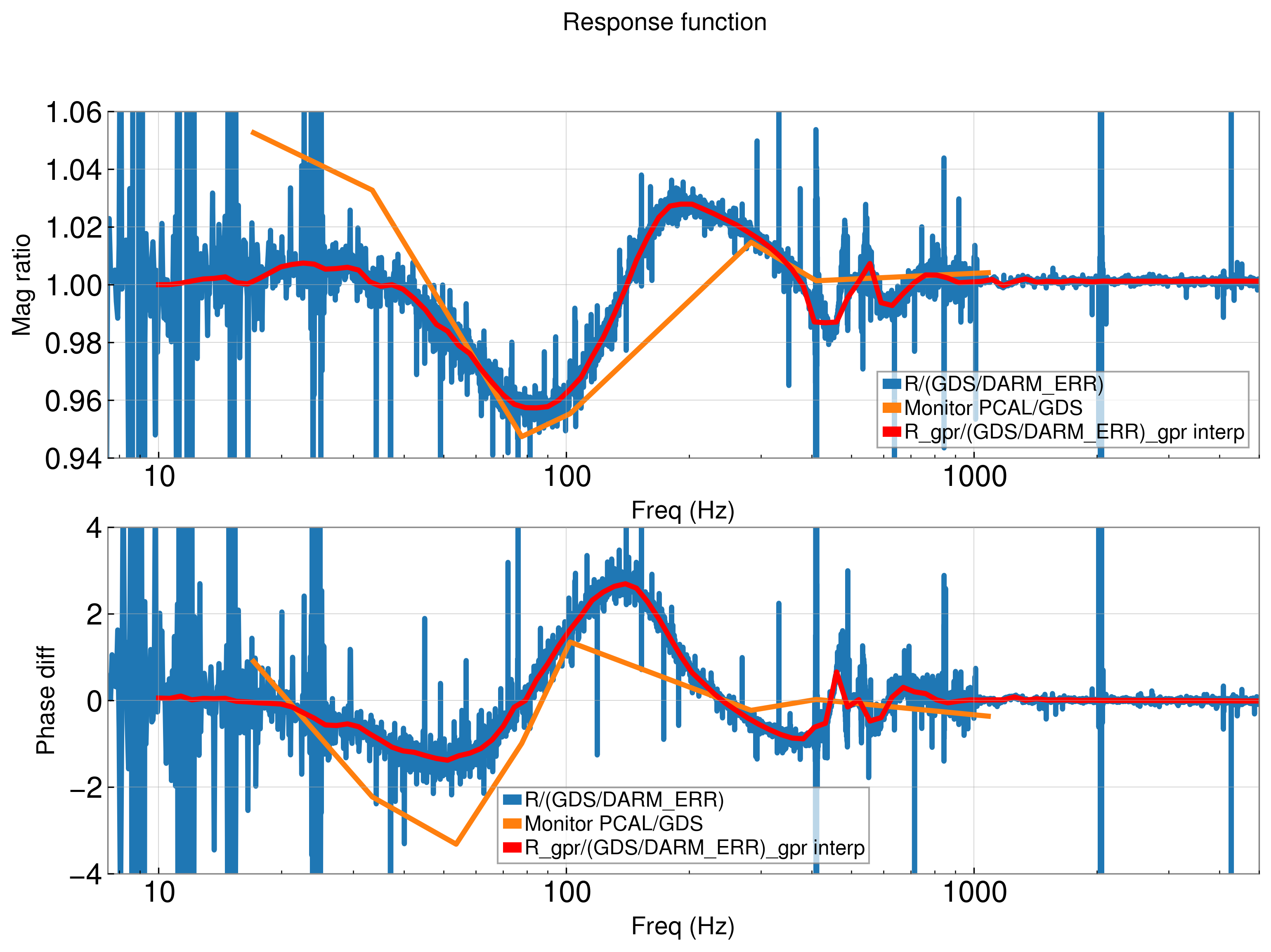
I make a direct measurement of this systematic error by dividing CAL-DARM_ERR_DBL_DQ / GDS-CALIB_STRAIN , where the numerator is further corrected for kappa values of the sensing, cavity pole, and the 3 actuation stages (GDS does the same corrections internally). This gives a transfer function of the difference induced from errors in the GDS filters.
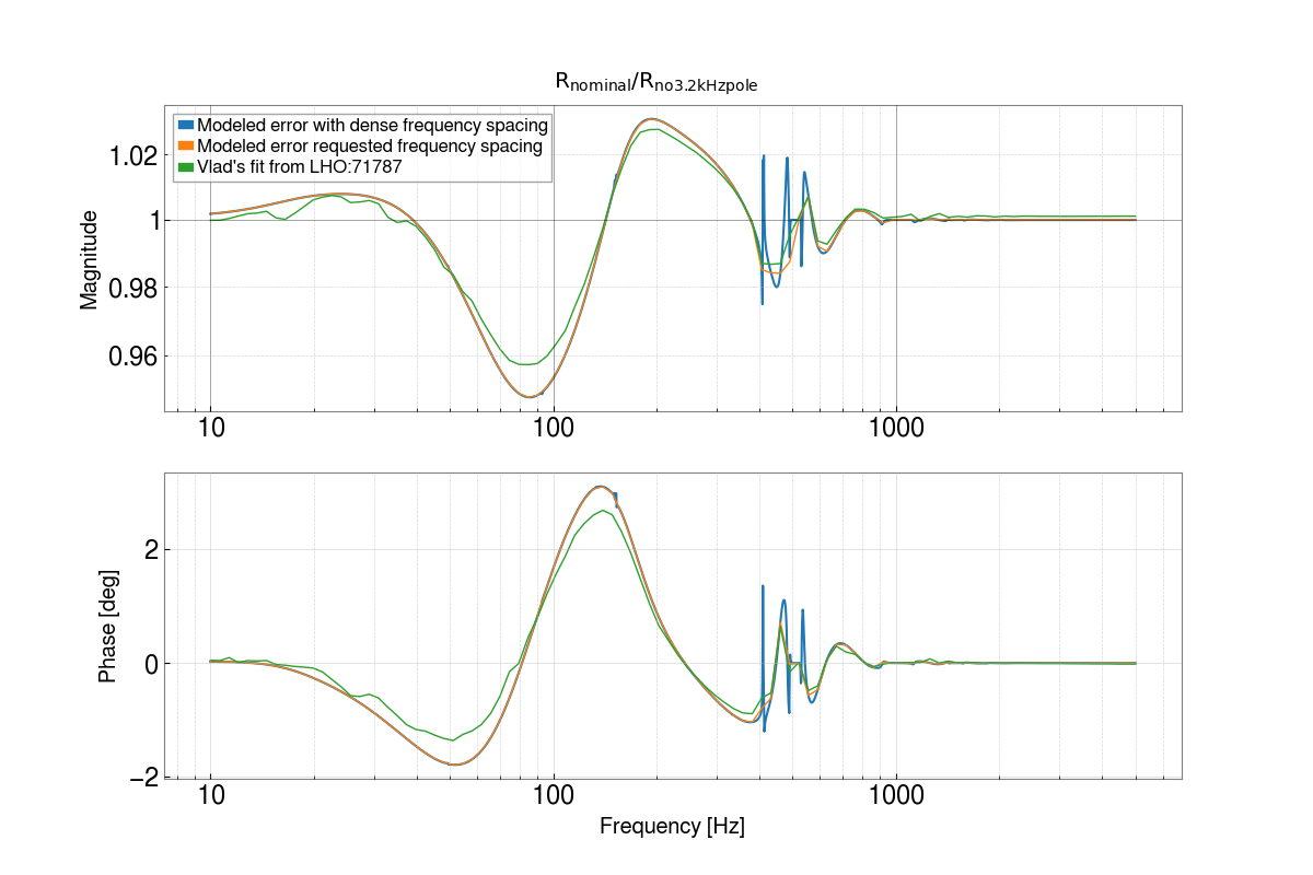
Attached in this aLog, and its sibling aLog in LLO, is this measurement in blue, the PCAL / GDS-CALIB_STRAIN measurement in orange, and the smoothed uncertainty correction vector in red. Attached also is a text file of this uncertainty correction for application in pyDARM to produce the final uncertainty, in the format of [Frequency, Real, Imaginary].
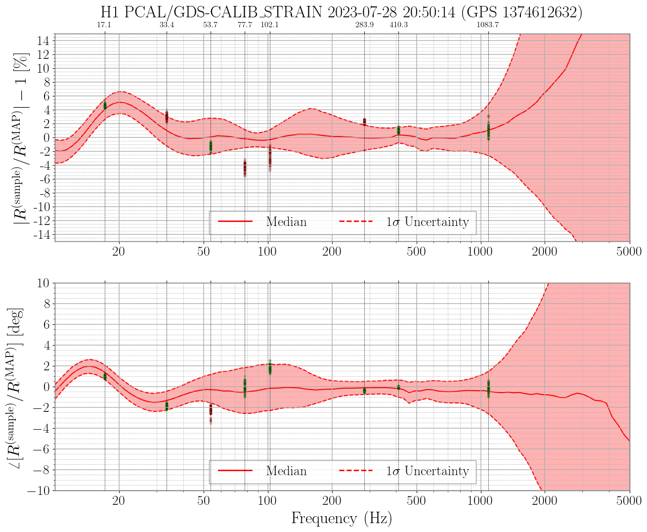
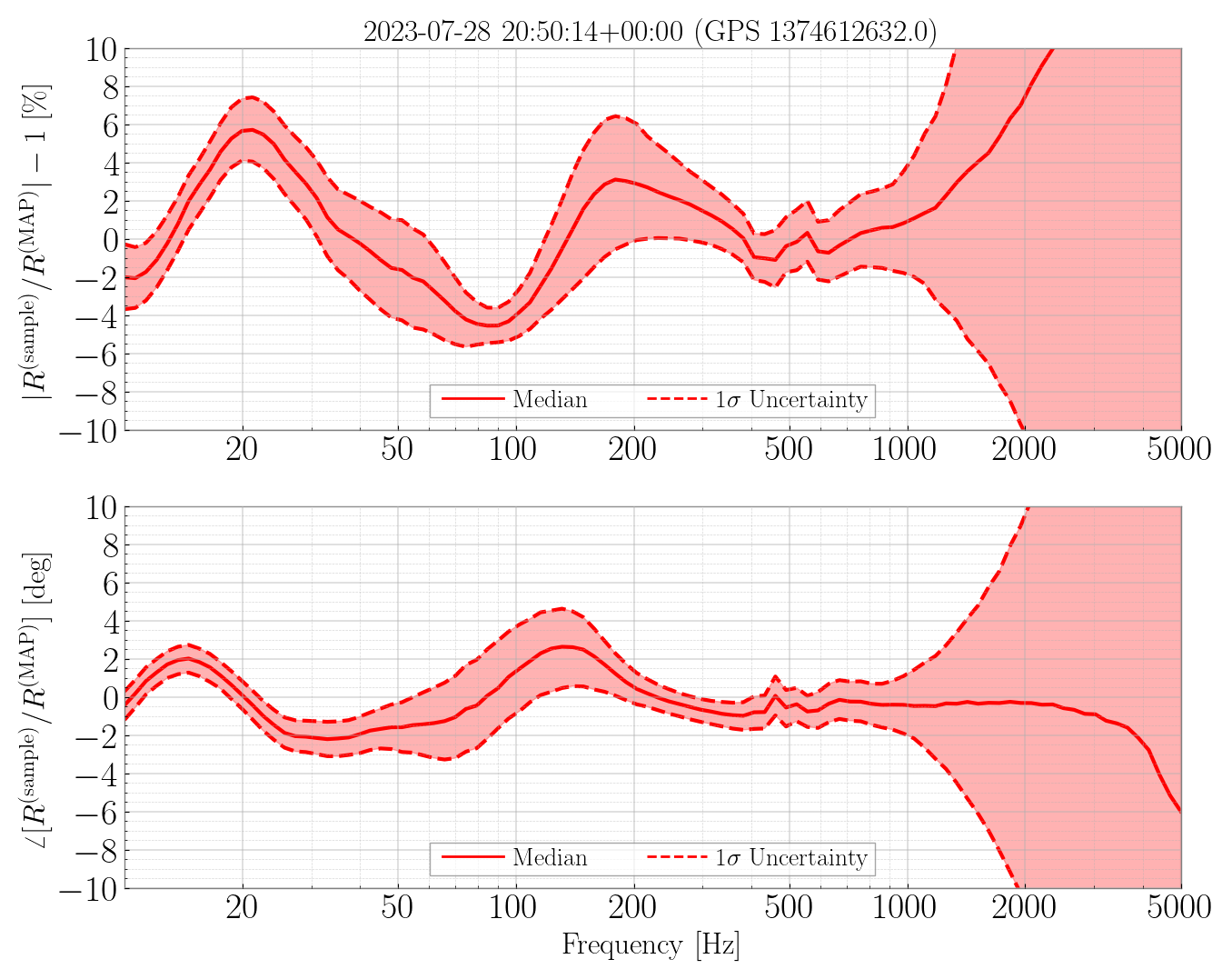
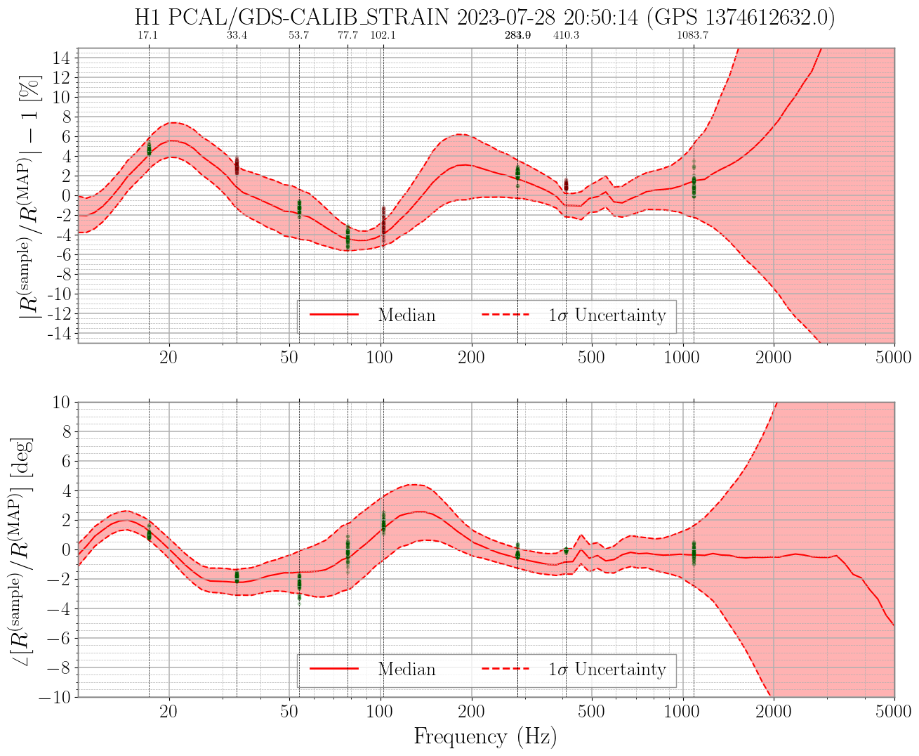
After running the command documented in alog 70666, I've plotted the monitoring results on top of the manually corrected uncertainty estimate (see attached). They agree quite well.
The uncertainty is estimated at 1374612632 (span 2 min around this time). The monitoring data are collected from 1374612632 to 1374616232 (span an hour).
Images attached to this comment
jeffrey.kissel@LIGO.ORG - 17:01, Wednesday 13 September 2023 (72871)
J. Kissel, J. Betzwieser

FYI: The time at which Vlad used to gather TDCFs to update the *modeled* response function at the reference time (R, in the numerator of the plots) is
    2023-07-27 05:03:20 UTC
    2023-07-26 22:03:20 PDT
    GPS 1374469418

This is a time when the IFO was well thermalized.

The values used for the TDCFs at this time were
    \kappa_C  = 0.97764456
    f_CC      = 444.32712 Hz
    \kappa_U  = 1.0043616
    \kappa_P  = 0.9995768
    \kappa_T  = 1.0401824

The *measured* response function (GDS/DARM_ERR, the denominator in the plots) is from data with the same start time, 2023-07-27 05:03:20 UTC, over a duration of 384 seconds (8 averages of 48 second FFTs).

Note these TDCF values list above are the CAL-CS computed TDCFs, not the GDS computed TDCFs. They're the value exactly at 2023-07-27 05:03:20 UTC, with no attempt to average further over the duration of the *measurement*. See attached .pdf which shows the previous 5 minutes and the next 20 minutes. From this you can see that GDS was computing essentially the same thing as CALCS -- except for \kappa_U, which we know
 - is bad during that time (LHO:72812), and
 - unimpactful w.r.t. the overall calibration.
So the fact that
    :: the GDS calculation is frozen and
    :: the CALCS calculation is noisy, but is quite close to the frozen GDS value is coincidental, even though
    :: the ~25 minute mean of the CALCS is actually around ~0.98 rather than the instantaneous value of 1.019
is inconsequential to Vlad's conclusions.
I'm adding the modeled correction due to the missing 3.2 kHz pole here as a text file. I plotted a comparison showing Vlad's fit (green), the modeled correction evaluated on the same frequency vector as Vlad (orange), and the modeled correction evaluated using a dense frequency spacing (blue), see eta_3p2khz_correction.png. The denser frequency spacing recovers error of about 2% between 400 Hz and 600 Hz. Otherwise, the coarsely evaluated modeled correction seems to do quite well.


[ TJ, Erik, Richard ]
Failure happend at 13:16:22 UTC.
The second ADC showed timeout. On reboot of the front end, the Linux kernel crashed.
Richard cycled power on the IO Chassis and we rebooted the front end again. This time it did not crash, but could not see the second DAC.
This sounds similar to the events a year ago described here: https://alog.ligo-wa.caltech.edu/aLOG/index.php?callRep=66570
Richard is going to re-seat the second DAC.
Richard found that the LEDs on the second DAC did not come up as they did with the first DAC. The second DAC again did not appear on the PCI bus.
Richard is going to replace it.
We're back up and running with the new DAC.
16 Bit DAC Installed: SN 180904-122
16 Bit DAC Removed: SN 100922-07