At today's commissioning meeting, we decided that we would very, very slowly move PR3 while in Observe, so see if we could further reduce clipping in the PRC / in the POP pickoff path.
To check that I could move the PR3 sliders while in Observe, I clicked the 'MASK' button in the SDF to ALL (so that I could see which two channels are not monitored in the PR3 SDF). Indeed the PR3 sliders are not monitored, but just checking that brought us out of Observe briefly. The Operator brought us back to Observe a few seconds later. Naoki and I also unmonitored the _TRAMP channels for PR3's sliders, but that did not take us out of Observe.
Set the TRAMPS to 10 sec from nominal 2 sec.
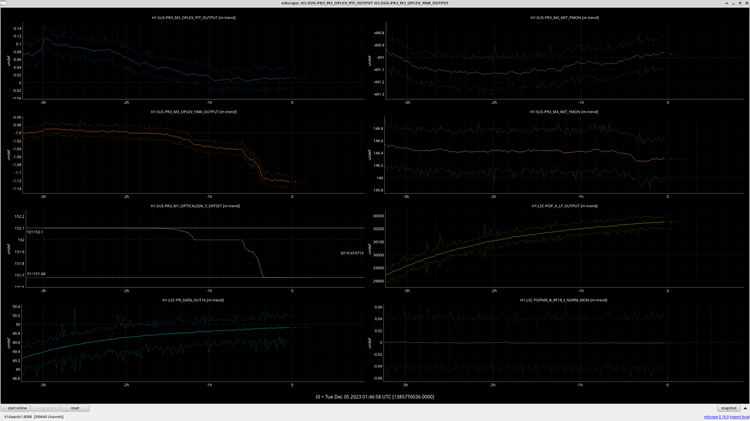
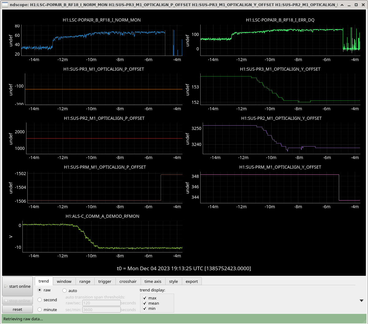
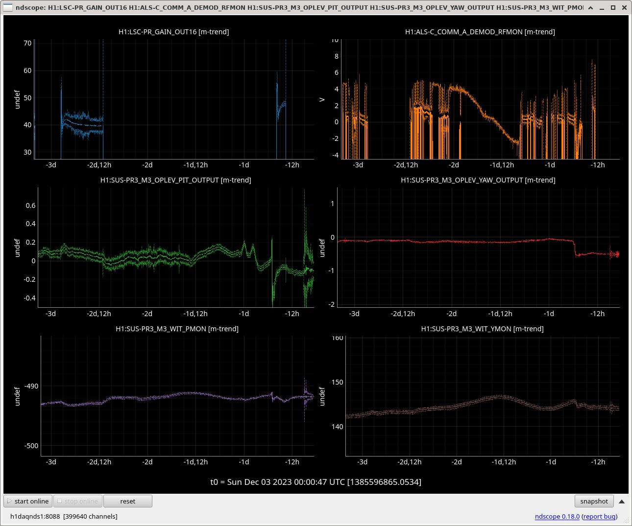
Yaw steps of -0.0001 are okay. -0.0003 start to see things in the camera signals, so seem too big for Observing. Kept taking steps of -0.0001 every ~30 sec. Moved a total of -0.002 PR3 yaw. Now sitting for a few minutes of quiet, starting at 5 Dec 2023 00:00:00 UTC for 5 mins.
Naoki looked, and we can't see any yaw motion with my moves, although there's a teeny bit of pit motion. So we're going to try again the steps of -0.0003. Now, they seem to not cause a glitch, so the one earlier was probably a coincidence.
Increased step size to -0.001, seems okay.
Increased step size to -0.003, seems okay. Got to PR3 yaw offset slider of 152.000, so going to start some mins of quiet at 00:37:00 UTC. Quiet ended at about 01:10:00 UTC, although in between Robert went to the CER twice to turn off, then back on an AC unit.
Seems like the things I was worried about being glitches are just peaks of the CER ACs (but not the one that has been a problem in the past, since Robert turned that off for a few mins and we didn't see a change). So, bigger step size of -0.01 is going okay.
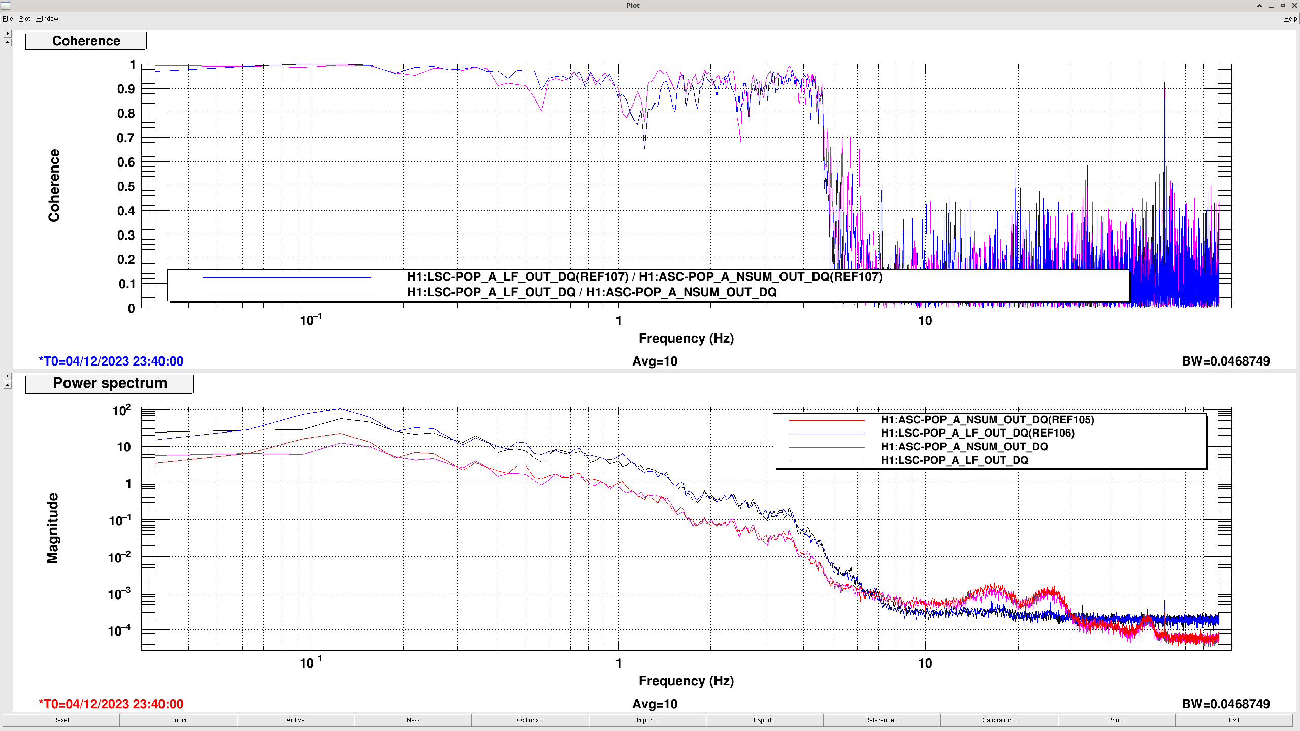
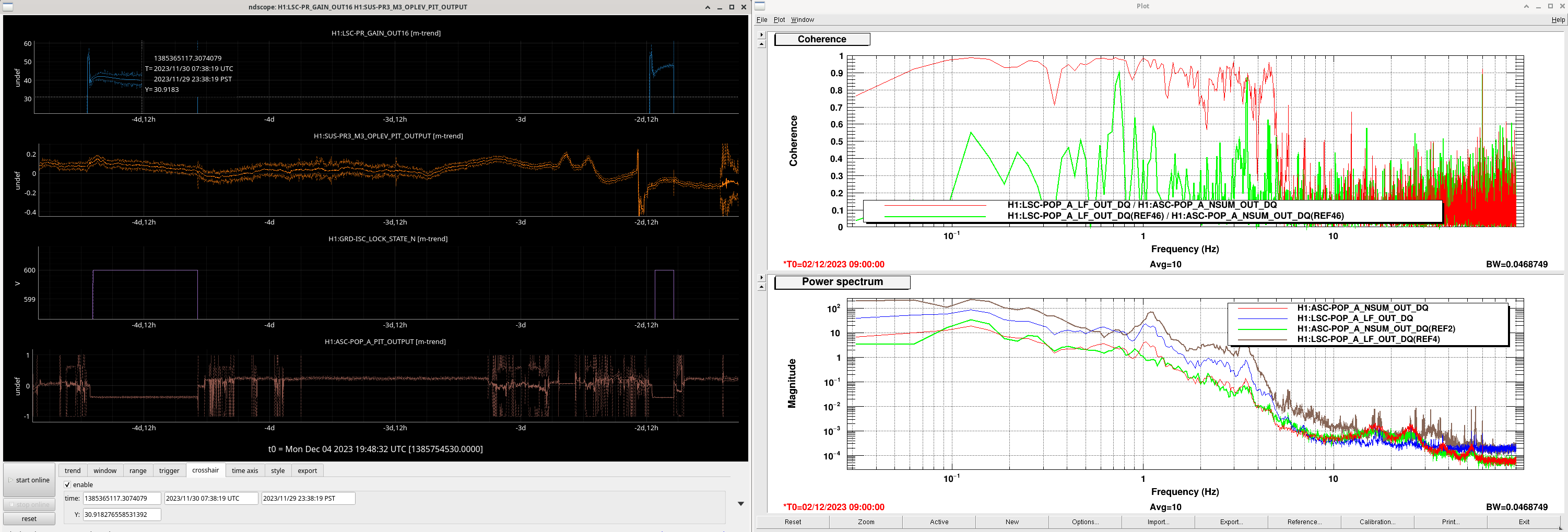
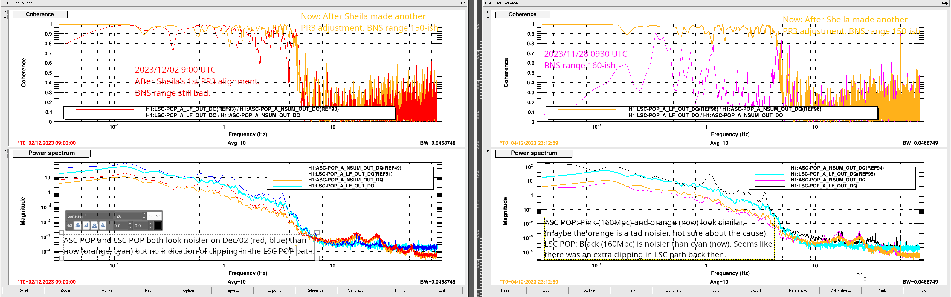
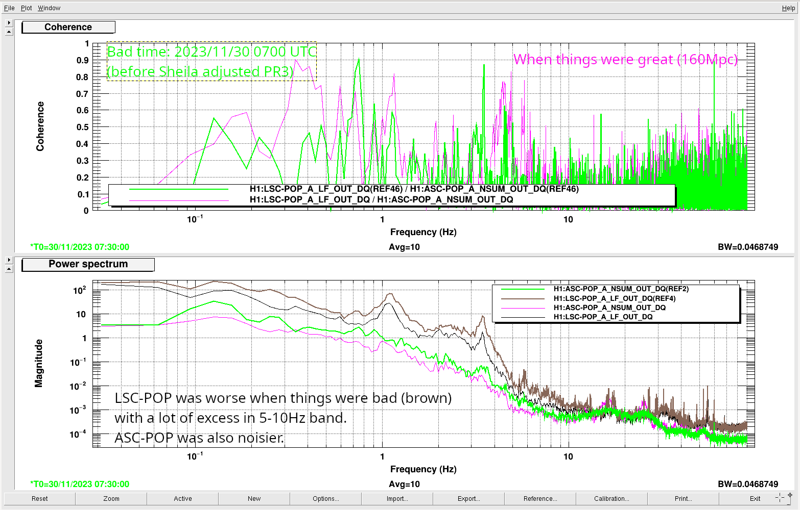
I'm stopping for now. We've moved about 0.2 urad in yaw, continuing in the direction that Sheila did earlier today (Sheila did a little more than 1urad when in PRMI only). Naoki is making a plot showing that the coherence between the LSC and ASC POP sensors is basically the same now as after Sheila's move earlier. So, I think we're at least not on the edge of clipping, and that it's a better use of time to do more moves during a PRMI or DRMI lock, when we can move faster and see about finding the center of our clipping aperture.