Naoki, Sheila
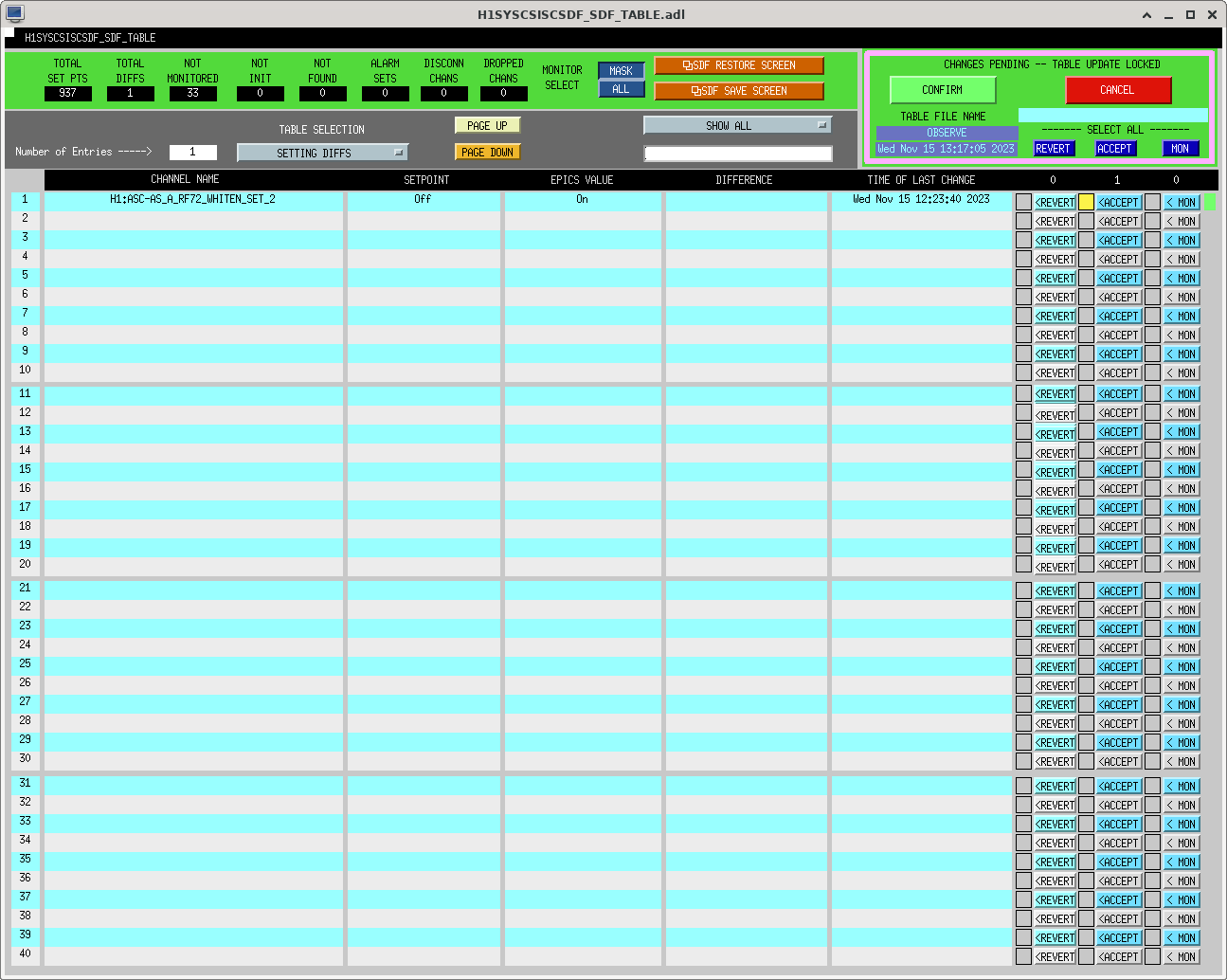
In the AS72 sensing matrix measurement in alog74106, Daniel suggested to increase the whitening gain of AS72 since it could be limited by ADC noise. We checked the whitening filter of AS72 A and B. Both of them have 12dB whitening gain, but one stage whitening is engaged for AS72 A, while two stage whitening is engaged for AS72 B. We decided to engage the 2 stage whitening for AS72 A, which is used in SRC1. The IFO locks without any problem with this additional whitening. We accepted some SDFs as shown in the attached figures. We will try to increase the whitening gain later.
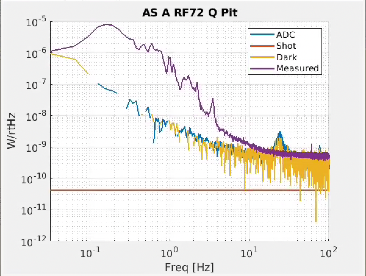
I think the attached plot shows this was a good idea. I have some old data measuring whitening and no whitening on at RF72, but I never posted it because I couldn't figure out the correct RF72 transimpedance. The attached plot shows an estimation of the ADC noise level comparison with the noise spectrum in lock. Naoki and Daniel were kind enough to help me figure out the proper transimpedance for the RF72 (see 37065).
The measurement procedure and calculation procedure is detailed in alog 66734. At the time, RF72 was using 1 stage of whitening with 12 dB whitening gain.
I think it's likely my shot noise calculation here is incorrect. Correcting that calcuation is in progress...
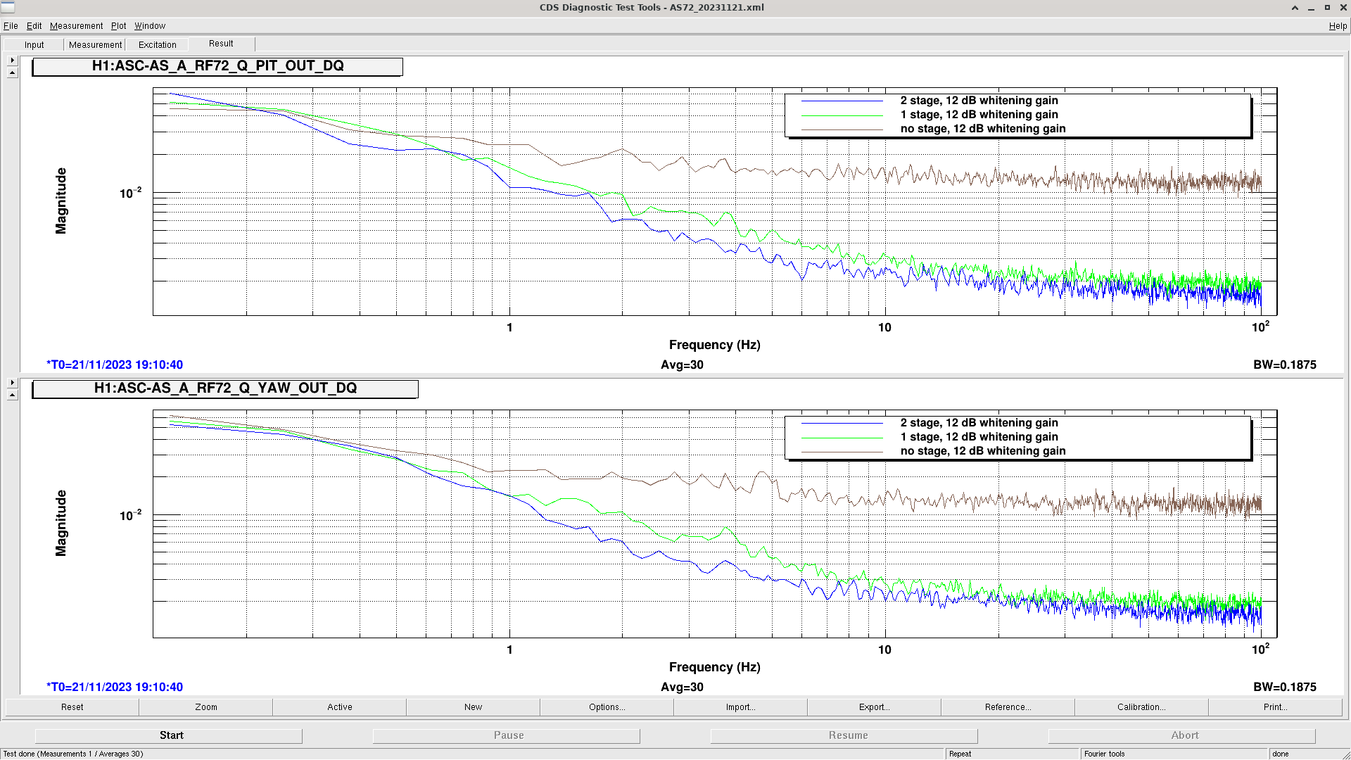
During Tuesday maintenance and IMC_LOCK is OFFLINE, I measured the AS72 dark noise with different whitening setting. The attached figure shows the dark noise of AS72 A Q PIT/YAW, which are used in SRC1. The 2 stage whitening and 12 dB whitening gain are the current nominal setting. In the previous Elenna's measurement, there was a bump around 25 Hz, but there is no bump in today's measurement.
Sheila, Camilla, Naoki
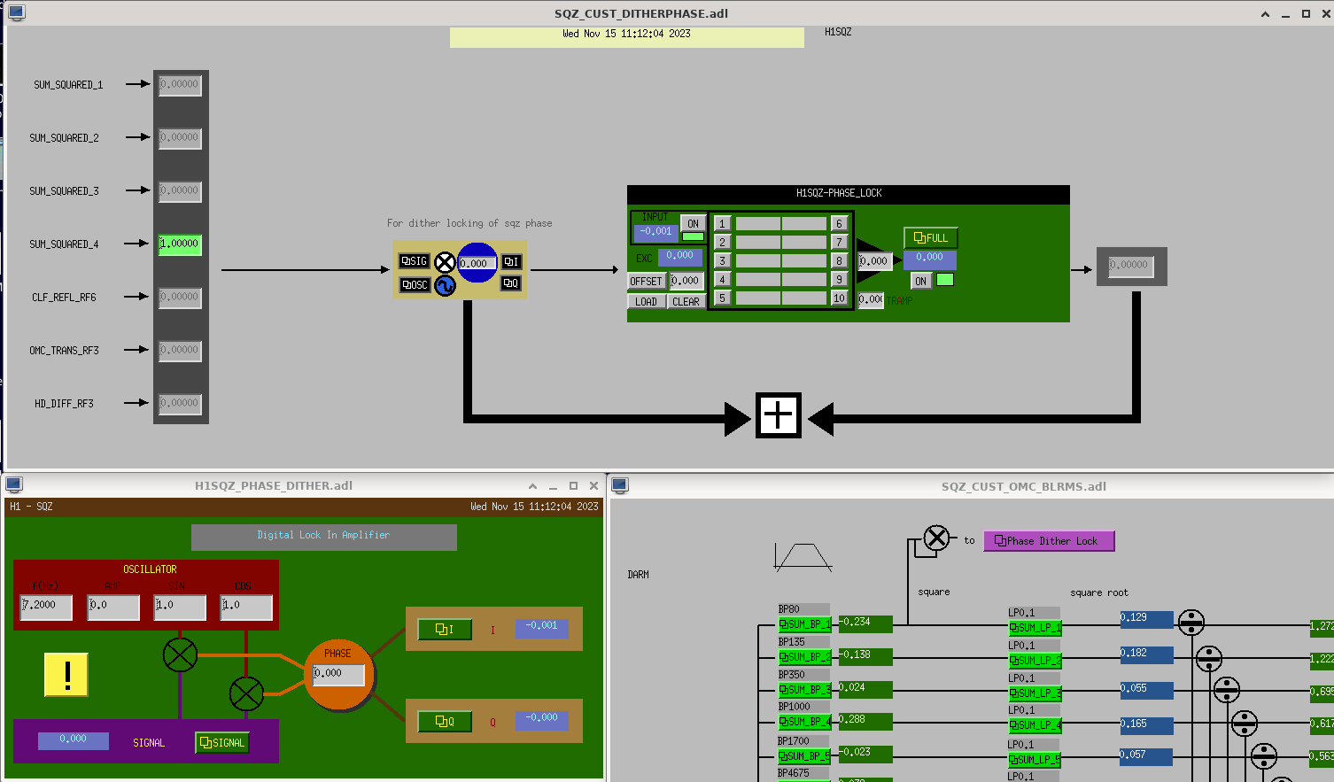
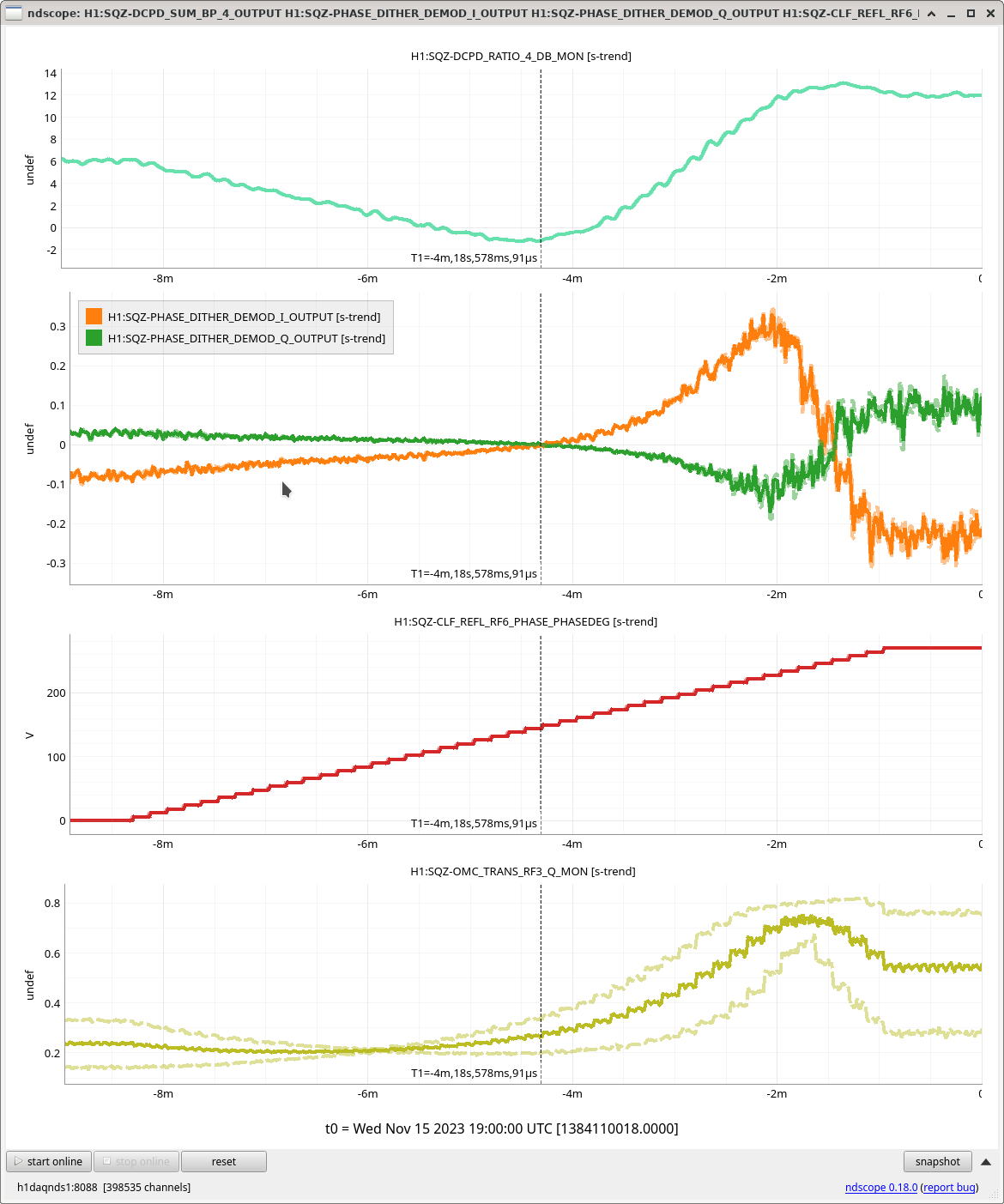
After alog74223, we engaged the SQZ phase dither servo as shown in the first attached figure. After we engaged the dither servo, the error signal (SQZ-PHASE_DITHER_DEMOD_I_OUTPUT) goes to 0 and the SQZ phase (SQZ-CLF_REFL_RF6_PHASE_PHASEDEG) goes to around optimal value.
Detail
First we checked the error signal of dither servo by scanning SQZ phase as shown in the second attached figure. The dither error signal is SQZ-PHASE_DITHER_DEMOD_I_OUTPUT shown in gray. You can see the two zero crossing points where the BLRMS4 (SQZ-DCPD_SUM_RMS4_MON) is minimum and maximum.
Then we made a new state in SQZ_MANAGER guardian named ADJUST_SQZ_ANG to adjust the SQZ phase using dither servo. The servo is engaged with cdu.Servo and it uses the SQZ-PHASE_DITHER_DEMOD_I_OUT16 as readback channel and the SQZ-PHASE-OUTMTRX_1_1 as control channel. We cannot use the SQZ phase (SQZ-CLF_REFL_RF6_PHASE_PHASEDEG) as control channel since it is a discrete number (SQZ-CLF_REFL_RF6_PHASE_DELAYSTEP must be an integer). So we stored the value of the DELAYSTEP in the unused output matrix element (SQZ-PHASE-OUTMTRX_1_1) and used it as control channel. The DELAYSTEP itself is controlled by rounding the value of SQZ-PHASE-OUTMTRX_1_1 to an integer.
Note: Although the SQZ phase dither servo seems to work, the SQZ phase the servo ended up (152.7 deg) is not exactly optimal value (145.47 deg). We needed to adjust the SQZ phase manually to really optimize the SQZ BLRMS.
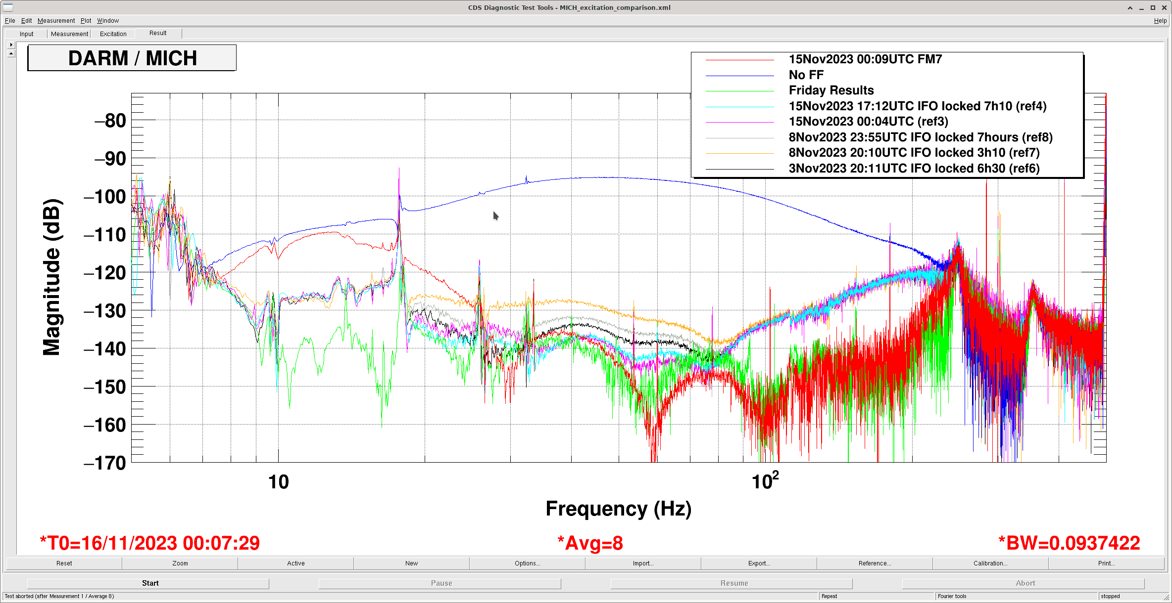
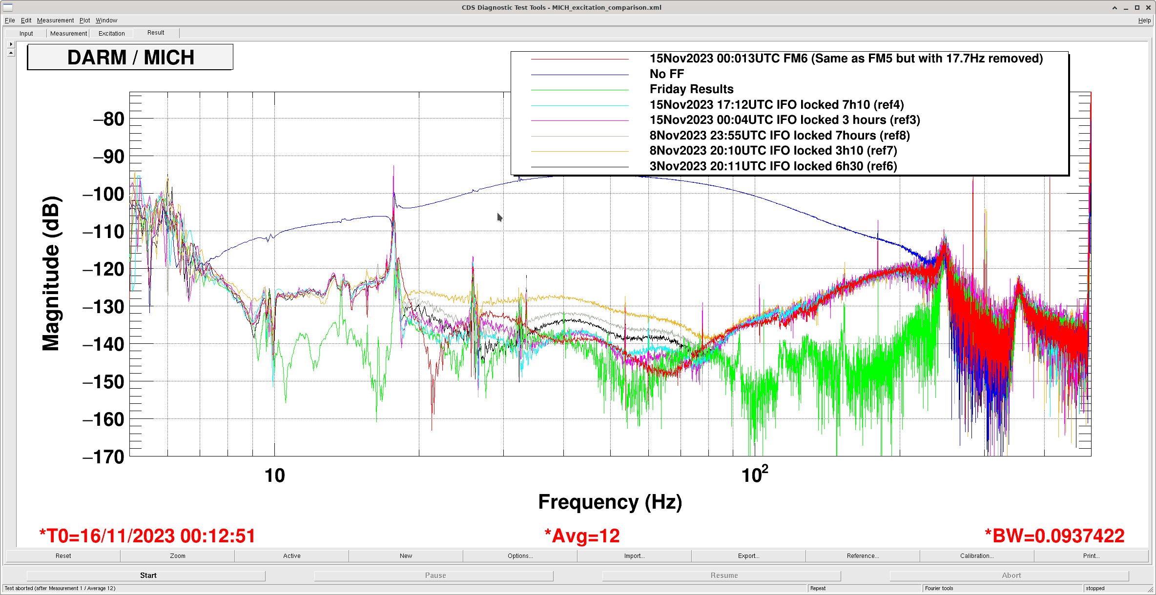
This morning I took measurements for MICH and SRCL feedforward and exported in .txt files in /lsc/h1/scripts/feedforward. Gabriele changed SRCL in 73662 Oct 20th. MICH last changed 73420 Oct 12th.
I didn't have good luck re-fitting MICH, I made a new filter in FM7 but although it fit 100-200Hz well, I couldn't get the fit to also be good <20Hz. Plot attached - RED TRACE.
I also tried the current FF without 17.7Hz line, FM6, 74139, it alos change the fit of the filter 20-80Hz, wasn't sure if this was better or worse so will discuss with others and we can implement on Friday. Plot attached, RED TRACE.
Strangely, the current MICH FF looked better than it has done recently and didn't appear to change with thermalization. What has changed since last week 74102?!
TITLE: 11/16 Eve Shift: 00:00-08:00 UTC (16:00-00:00 PST), all times posted in UTC
STATE of H1: Observing at 155Mpc
OUTGOING OPERATOR: TJ
CURRENT ENVIRONMENT:
SEI_ENV state: CALM
Wind: 6mph Gusts, 5mph 5min avg
Primary useism: 0.02 μm/s
Secondary useism: 0.30 μm/s
QUICK SUMMARY:
TITLE: 11/16 Day Shift: 16:00-00:00 UTC (08:00-16:00 PST), all times posted in UTC
STATE of H1: Observing at 155Mpc
INCOMING OPERATOR: Ryan C
SHIFT SUMMARY: One lock loss from commissioning with an automated relock during the shift. Most of the shift has been occupied by commissioning time, but we are back to observing at 0033 UTC.
LOG:
Louis and I have been looking at increasing the offloading of the signal from the ESD to the PUM and UIM, in light of 73913.
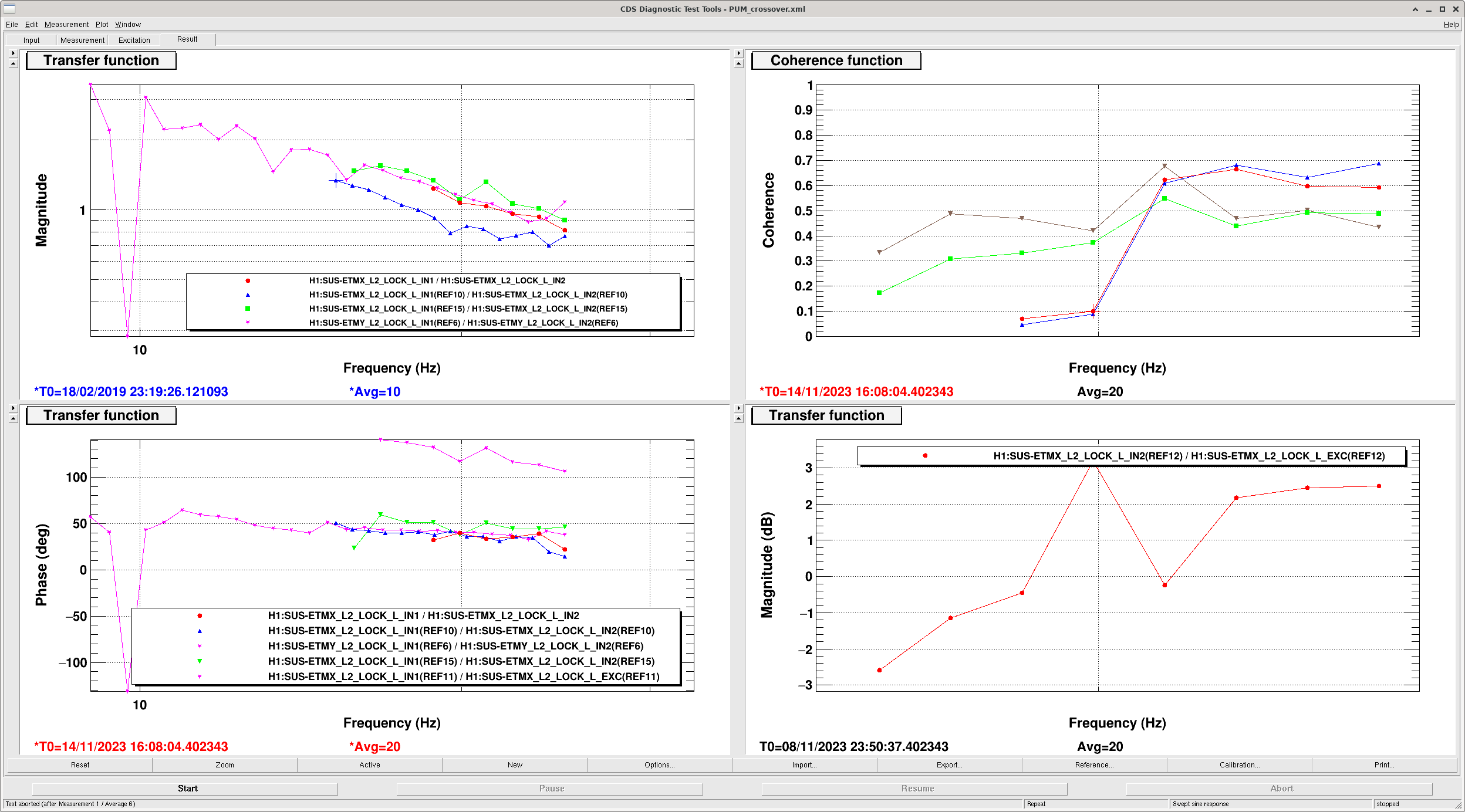
I have attempted a few times to make measurements by exciting at the L2 LOCK L filter, this results in poor coherence even for amplitudes that are quite large in DARM, and turning up the amplitude slightly has caused a lockloss by saturating the ESD.
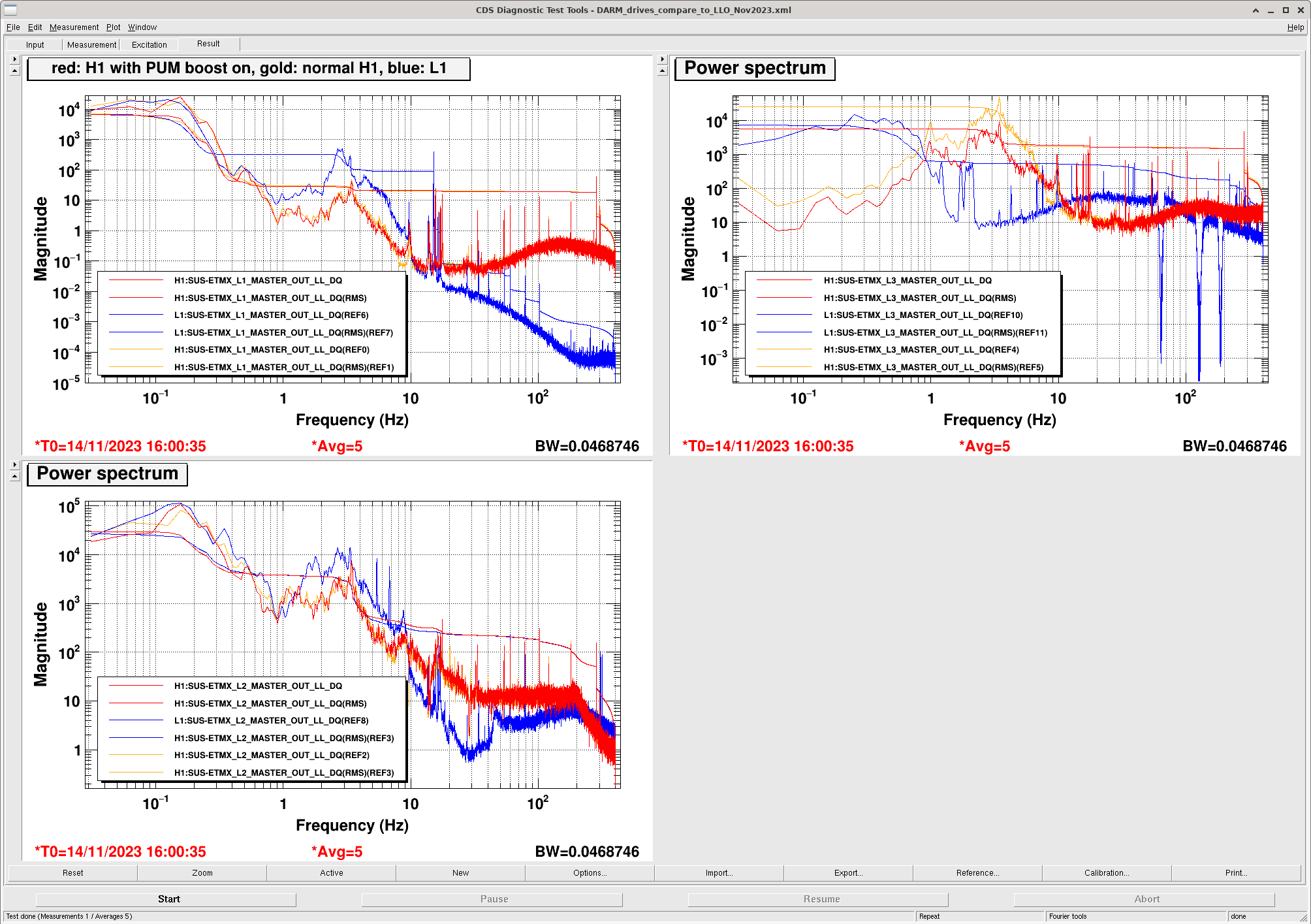
On Tuesday morning I engaged the PUM boost (L2 LOCKL FM2, boost4.5 which is a boost with a little resG aaround 4.5Hz). Some history (with links to old alogs about this filter is here: 48767) we used to run with this boost but turned it off in early O3 because angle to length cross couplings were causing instabilities of the DARM loop. On Tuesday morning I engaged this boost, and we stayed locked. The first attachment shows a comparison of our ETMX drives to LLO's (LLO also uses ETMY L1 for DARM control, but I haven't plotted that here), H1's usual configuration is in gold and the time with the PUM boost engaged is in red. The ESD drive RMS is reduced by more than a fator of 2 with the PUM boost engaged. I quickly tried a swept sine injection, and saw that the coherence was somewhat better than earlier measurements with a very small amplitude injection, so it seemed promising that we might be able to get a better measurement of the cross over with the PUM boost engaged.
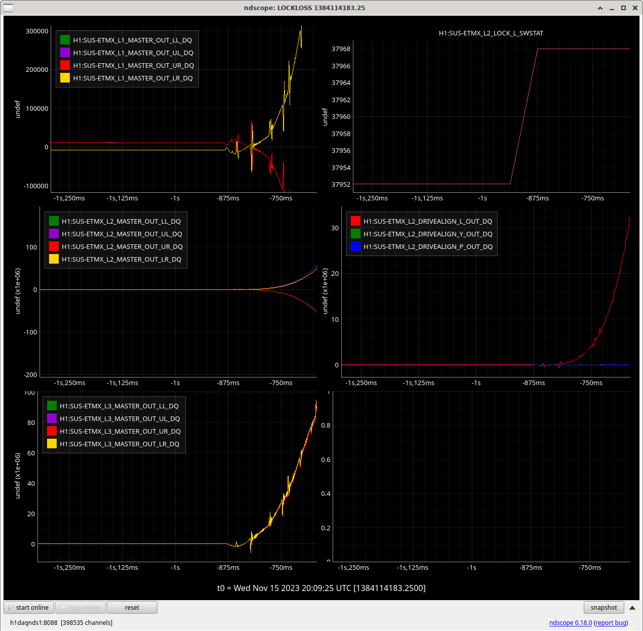
Today I engaged this boost again during commisoning time and we immediately lost lock. The third attachment shows that turning on the boost certainly seems to be the cause of the lockloss.
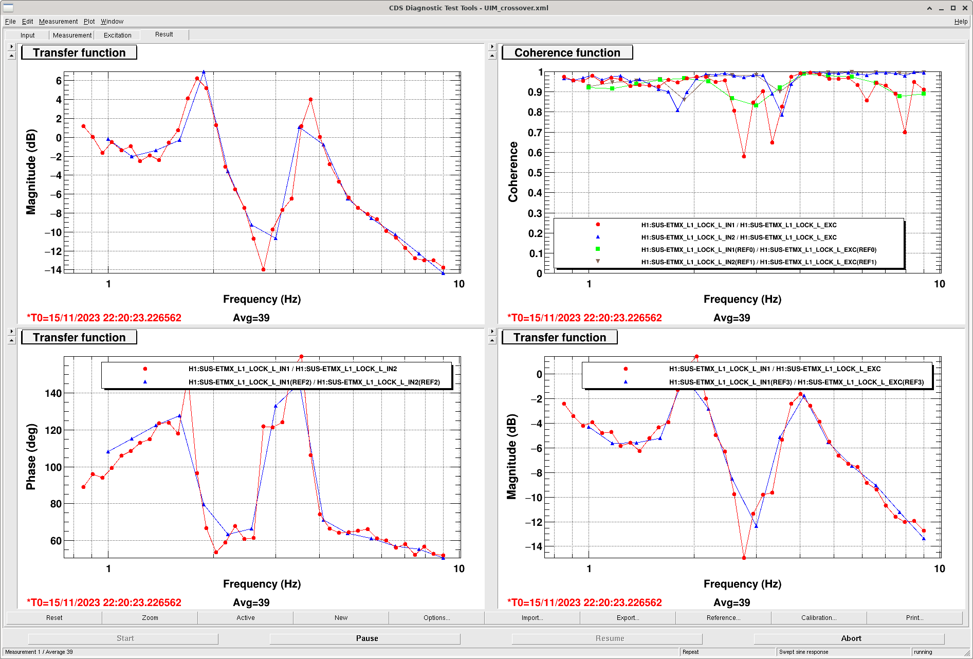
We can probably rely on the pyDARM model for the PUM crossover, since the calibration measurements validate the model above 10Hz. Today I was able to make a measurement of the UIM crossover, which Louis can use to compare to pyDARM from 1-10Hz.
this is discussed in LHO:74771
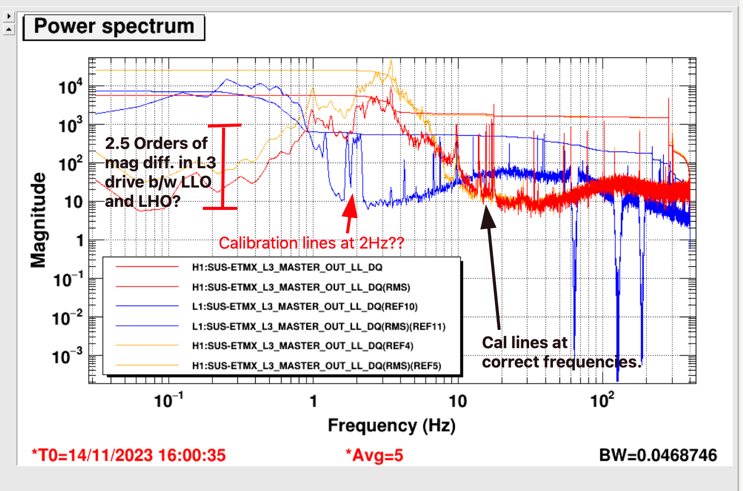
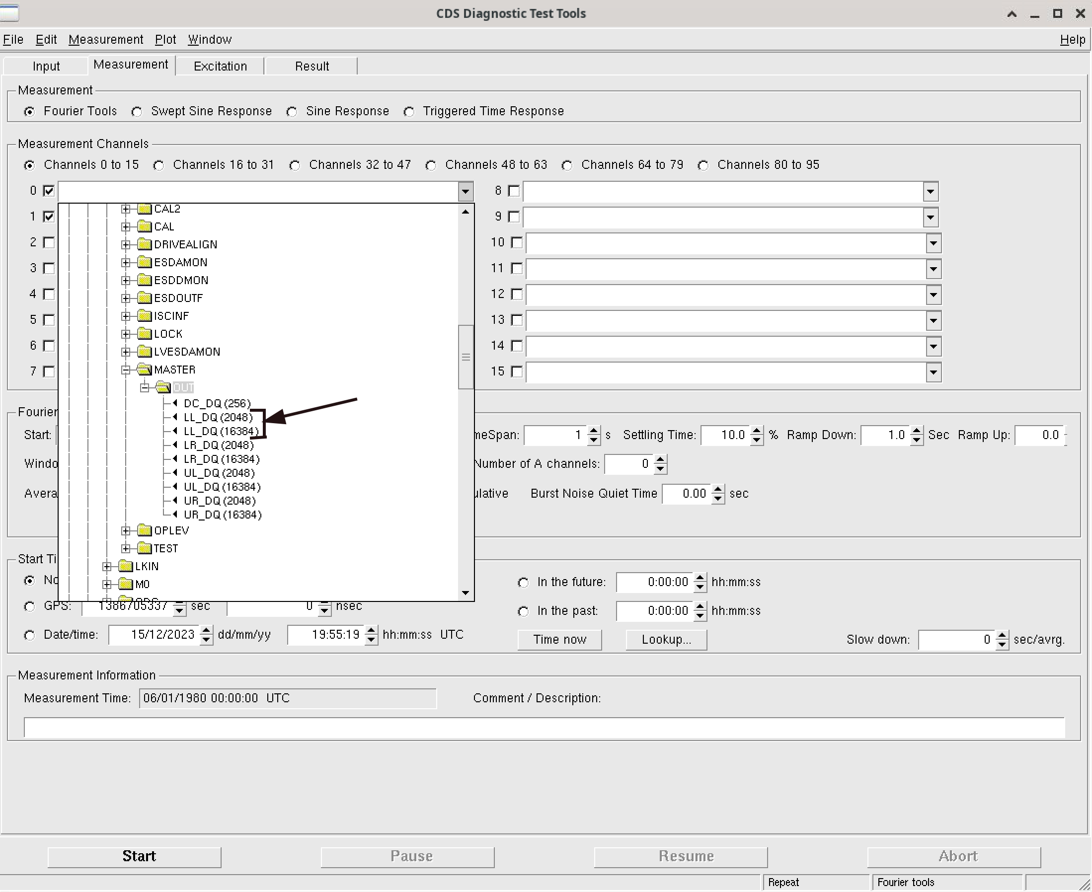
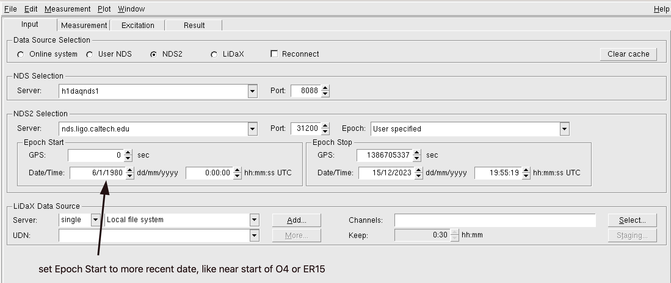
Gabriele, Louis The comparison between LLO's and LHO's ETMX L3 drive above (fist attachment in Sheila's post) confused us. The difference between the two LHO traces makes sense. But there are several things wrong with the channel from LLO (blue trace in top right hand plot). First of all, we do not have 2 orders of magnitude in difference between the L3 MASTER OUT drives at LLO vs LHO. Also, the calibration lines show up at the wrong frequencies in the LLO trace.It turns out that if you use NDS2 and leave the Epoch Start date at the default 6/1/1980, DTT sees two of some channels with the same name (but different sampling frequencies!), see DTT_NDS_issue.png. The result in this case was confusion of what DTT was plotting in Sheila's alog. We think that DTT got confused by having multiple channels with the same name but differing sampling frequencies in its lookup list, leading to DTT plotting the 16kHz channel but somehow applying the wrong sampling frequency. To avoid this, we had to re-remember to be careful when copying and pasting similar channel names from one text box to another within DTT and to set the Epoch Start field to something more reasonable than 1980.
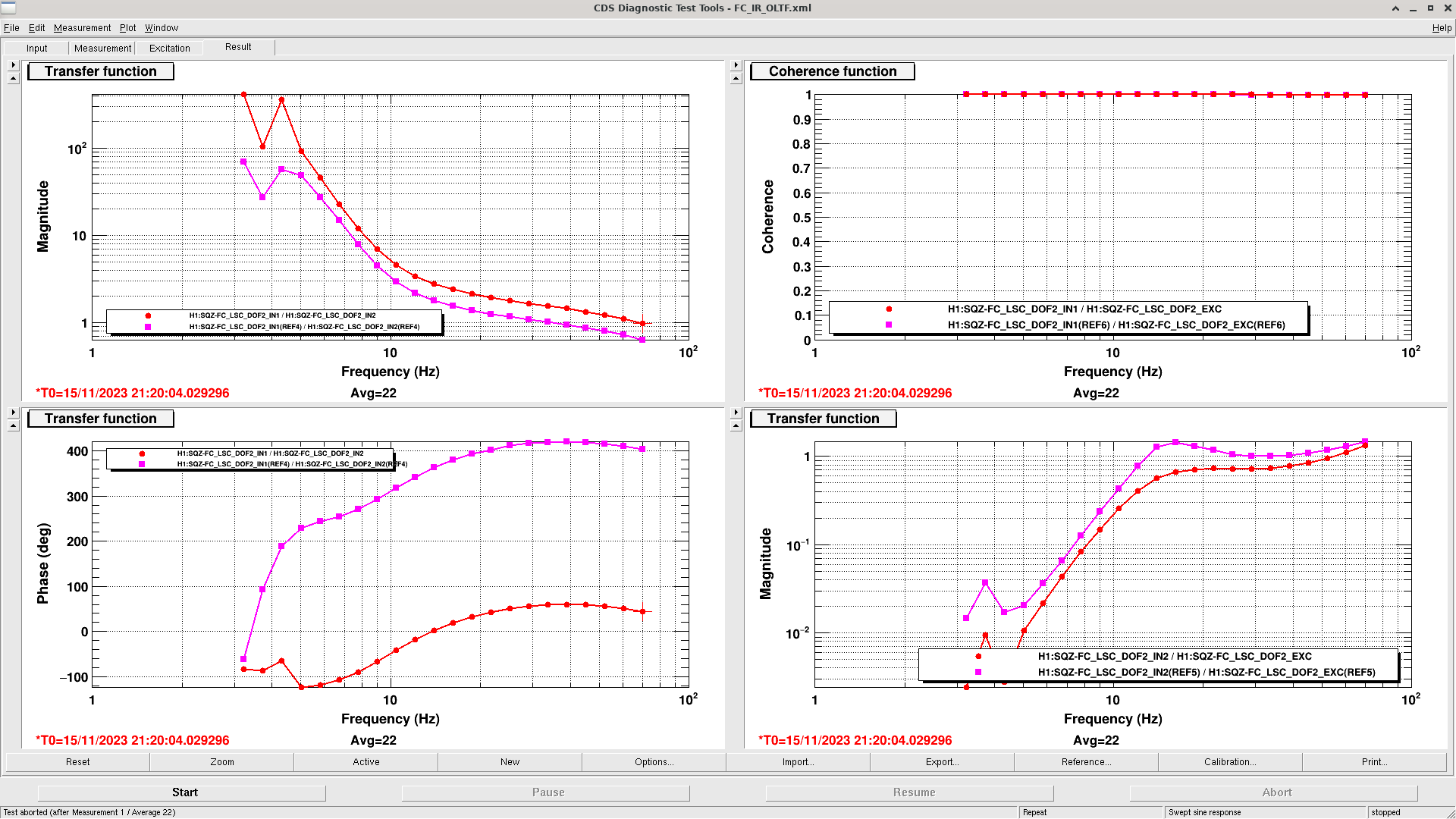
I measured FC IR OLG as shown in the attached figure. The FC IR OLG is higher than the purple reference on March 2023. So I decreased the IR gain from -5 to -3.5 and the OLG became similar to the purple reference. I updated the fc_wfs_a_ir_gain in sqzparams and loaded SQZ_FC guardian.
As commissioning started again, there was a commissioning caused lock loss. We are relocking now and almost back up. When we return to low noise commissioning will continue.
Sheila, Naoki, Camilla
Started testing a phase dither on the SQZ LO that dithers the SQZ angle, so that we can eventually demod the change on the SQZ BLRMS and use for monitoring and adjusting the SQZ level.
Yesterday
Sheila had already added all elements needed to the h1sqz model under H1:SQZ-PHASE and Naoki made a new medm screen (sitemap > sqz > sqz overview > sqz omc blrms > phase dither). GEO600 uses something similar to this and it's in 'Quantum noise locking' K.McKenzie Paper.
In the SQZ racks we plugged in the DAC output for the DITHER_OUT output into IN2 of the SQZ LO servo (chassis in right rack, slot 16). We had to unplug the "ISC_SQ_232" cable from IN2 of the LO board. If we want to the lock the LO using the homodyme again, we'll need to revert this.
Today during commissioning time we injected a 7.2Hz signal via H1:SQZ-PHASE_DITHER_OSC .
Copying whats used in ADS dither locks, we added added a bandpass around 7.2Hz to PHASE_DITHER_DEMOD_SIG to see the sqz angle dither using SQZ BRLMs #4, added low pass at 2Hz to PHASE_DITHER_DEMOD_{I,Q} as the 7Hz x 7Hz gives us a 14Hz and a 0Hz signal, we only want the 0Hz.
We made the #4 SQZ BLRMS use a wider band pass, was 700 to 800Hz, now 700 to 1750Hz. The signal got smoother, so we could think about expanding all the SQZ BLRMS.
Can already see the change demoded signal having a zero crossing a maximum and minimum squeezing as expected, see attached, where Sheila stepped the SQZ angle via the 'ezcastep' command. We still need to tune the demod phase to minimize Q and understand what amplitude we should use. We can also think about if we can achieve similar SQZ angle monitoring using the ADF signal.
To turn this back on: need to turn on IN2 on SQZ LO servo and put an amplitude in H1:SQZ-PHASE_DITHER_OSC_CLKGAIN. Other settings saved in sdf.
I've released a new version of the ndscope trend plot generator. The new system is more automated, making it easier for anyone to add trends to the system. Details are in the User Guide, which is a wiki page linked at to bottom of the web page.
Wed Nov 15 10:04:59 2023 INFO: Fill completed in 4min 56secs
Gerardo confirmed a good fill curbside.
Taking some time to do some opportunistic commissioning while LLO is down.
1906 UTC back to Observing
A contractor is on site to blow out our sprinklers. This work requires a large compressor to move air through the underground water lines near the OSB. Since we are observing and this specific noise source has not been vetted, we are marking the times here.
Rough start time: 1610 UTC
End time: Unfortunately we don't have a good end time. We would guess that this work would take roughly 30 minutes or less.
TITLE: 11/15 Day Shift: 16:00-00:00 UTC (08:00-16:00 PST), all times posted in UTC
STATE of H1: Observing at 151Mpc
OUTGOING OPERATOR: Corey
CURRENT ENVIRONMENT:
SEI_ENV state: CALM
Wind: 4mph Gusts, 3mph 5min avg
Primary useism: 0.02 μm/s
Secondary useism: 0.28 μm/s
QUICK SUMMARY: Locked for 6 hours, calm environment. Only alarm is the PT524B EX vacuum gauge that the vac team has been working on. Plans today consist of some commissioning time in the afternoon.
TITLE: 11/15 Eve Shift: 00:00-08:00 UTC (16:00-00:00 PST), all times posted in UTC
STATE of H1: Observing at 159Mpc
INCOMING OPERATOR: Corey
SHIFT SUMMARY: Pretty quiet night, I ran a calibration suite, and the range has been steadily just under 160 Mpc. Lock time of 9:35 at the end of the shift.
03:02 dropped observing to run a calibration measurement alog74212
03:32 Back to NLN, the DARM fom timed out during the state transition and I had to restart it
03:33 back into Observing
I've seen the MC3 camera on NUC26 flash blue a few times.
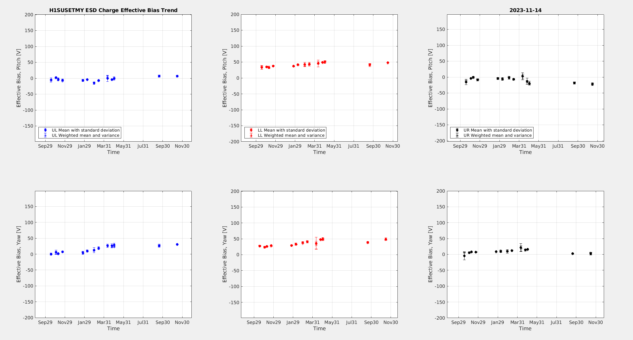
I ran the analysis for the OPLEV charge measurements on ETMY that Rahul took this morning. The charge on ETMY is fairly stable, some small increases and decreases on the quadrants since the last measurement.
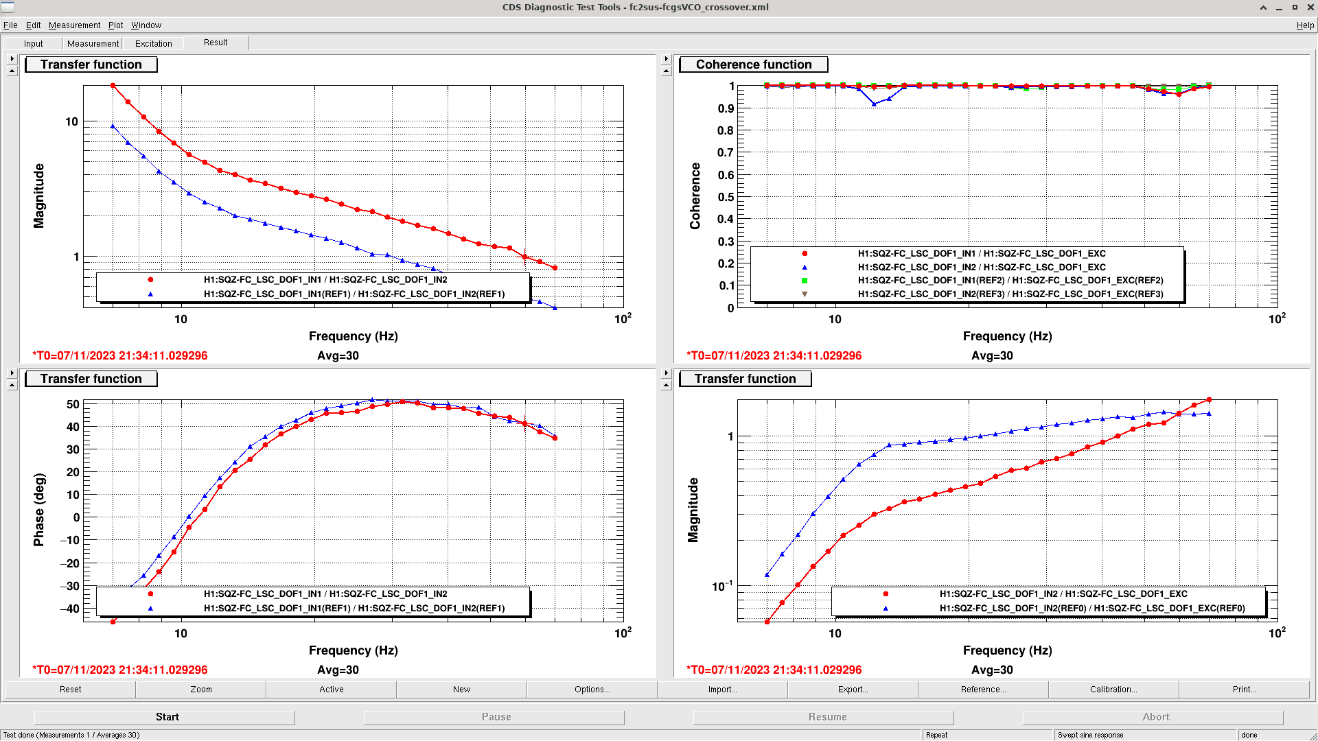
I checked the FC GR SUS/VCO crossover as shown in the attached figure. The crossover is about 60 Hz which is much larger than the blue reference on December 2022. This higher GR SUS gain could cause the instability during the transition from GR to IR. I reduced the GR SUS gain from 1 to 0.5 and the crossover became similar to the blue reference. I updated the SQZ_FC guardian to change this gain. Let's see if this helps the recent failure of FC GR to IR transition.
The green sus gain was defined in GR_SUS_LOCKING state of SQZ_FC guardian as follows.
ezca['SQZ-FC_LSC_INMTRX_SETTING_1_6'] = 0.5
In the previous alog, I changed the green sus gain by changing this line, but I think it is more convenient to define it in sqzparams. So I modified this line as follows.
self.GR_GAIN = sqzparams.fc_green_sus_gain
ezca['SQZ-FC_LSC_INMTRX_SETTING_1_6'] = self.GR_GAIN
And I defined fc_green_sus_gain = 0.5 in sqzparams.
I defined self.GR_GAIN = sqzparams.fc_green_sus_gain also in TRANSITION_IR_LOCKING state.
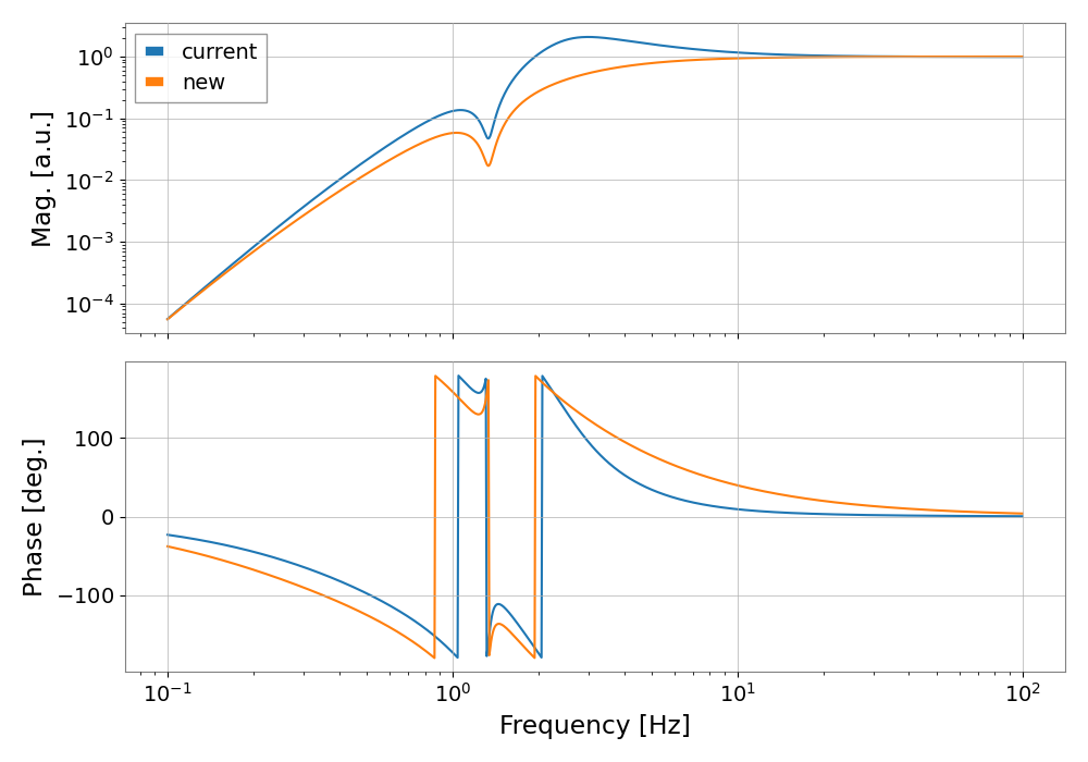
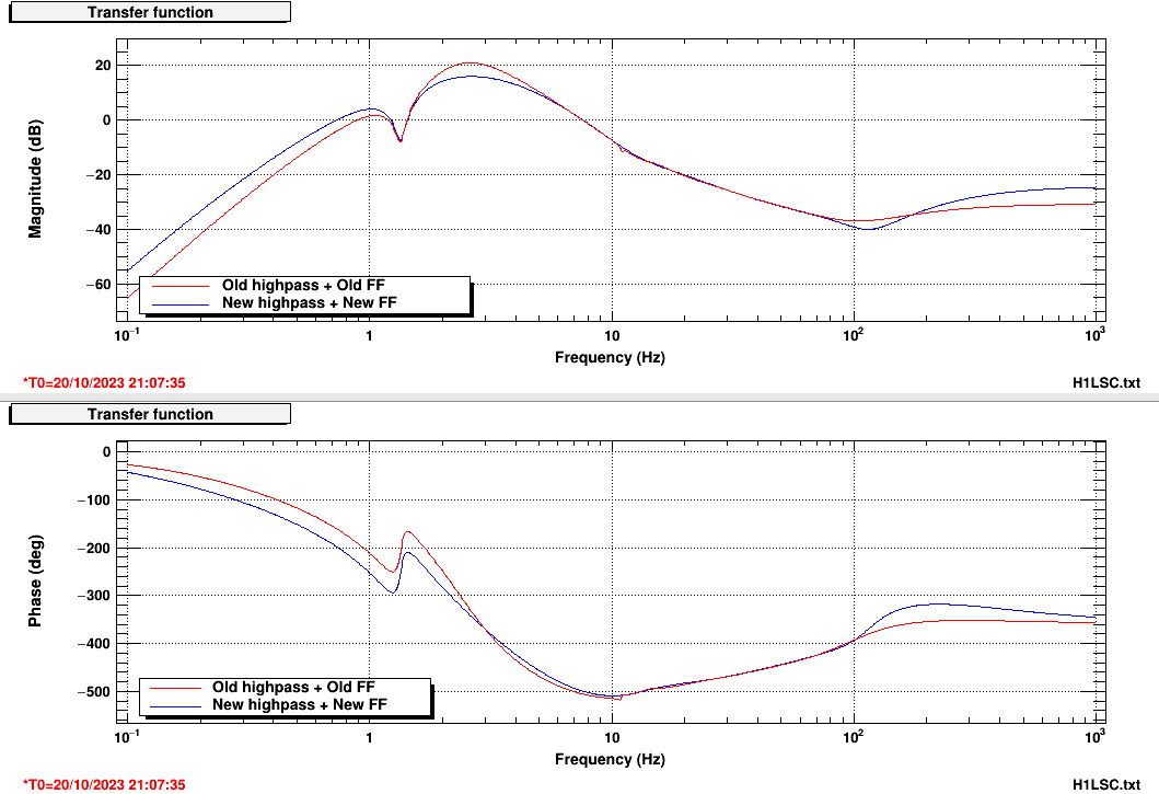
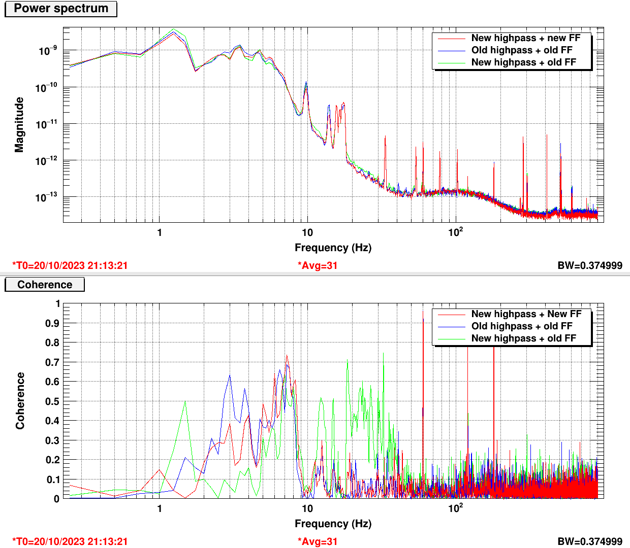
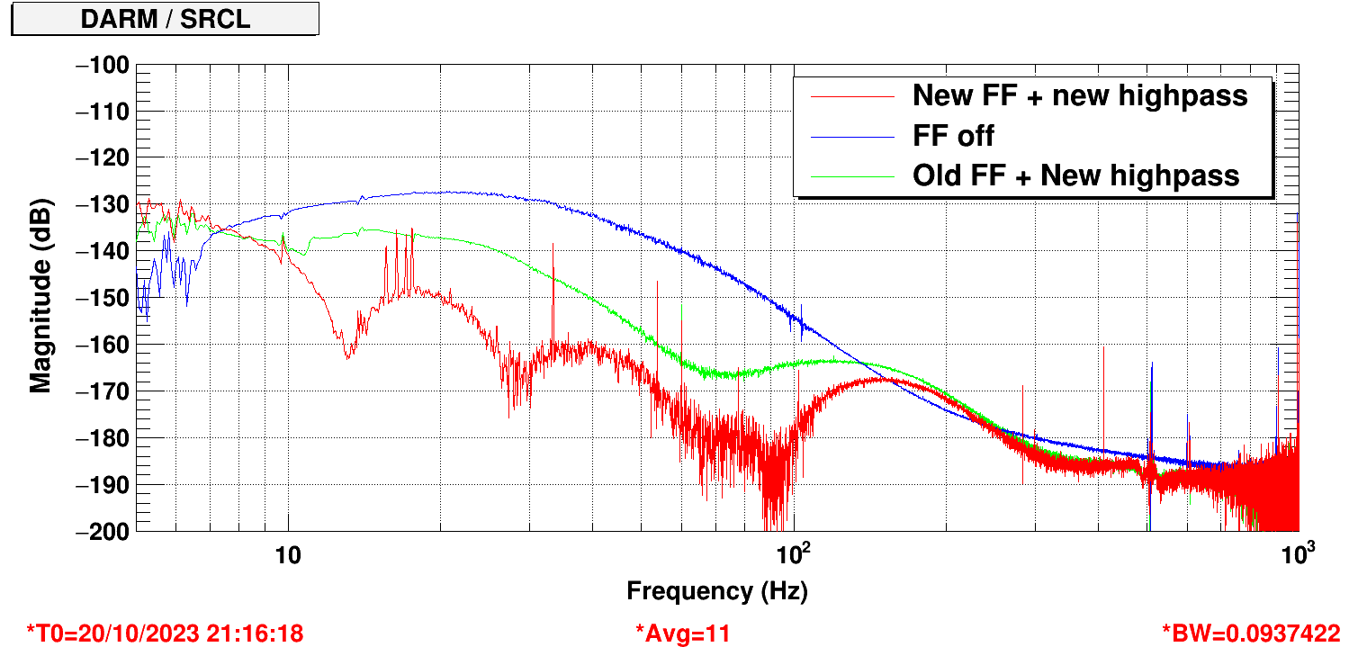
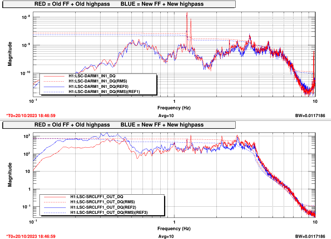
Following up on the observtion that the SRCL FF is increasing the DARM low frequency (2-3 Hz) motion (73561) and that this motion might be the origin of non-stationary noise (73546), I designed a new high pass filter for SRCLFF and retuned the FF.
The new high pass gives us about 4 times less reinjection between 2 and 4 Hz, at the price of a phase rotation of 20 degrees at 10 Hz. Therefore the old SRCL FF was not performing well anymore. I did a noise inection and refit the FF filter. Fitting this filter is tricky and I don't think I got an optimal solution. But it looks like the new highpass with the new FF performs fine, is at least as effective as the old highpass and the old FF, by looking at the coherence between DARM and SRCL.
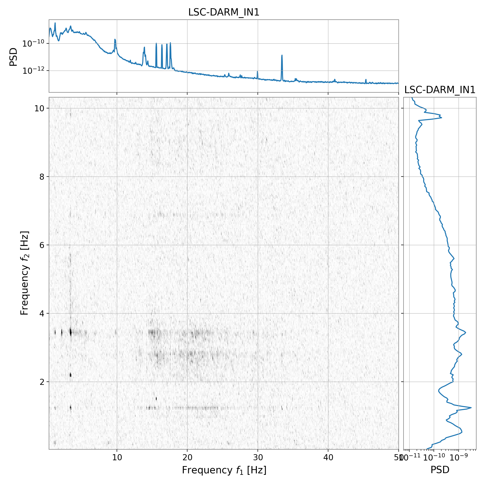
DARM RMS is improved a little between 3 and 4 Hz, so maybe we'll see some improvement in the non-stationary noise. We need to figure out what else is making DARM noise at 3.4 Hz. There is also an enormous line at 1.23 Hz that is the cause of most of DARM RMS. I think the bicoherence shows that the 1.23 Hz line is a source of noise modulation too.
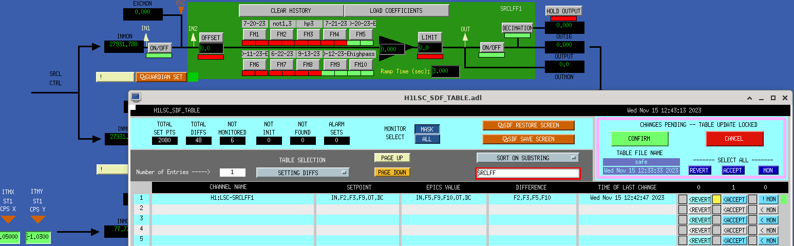
Noticed the old SRCLFF1 HP filters were being turned on in sdf revert so updated the safe.snap for the current highpass and filter, attached.