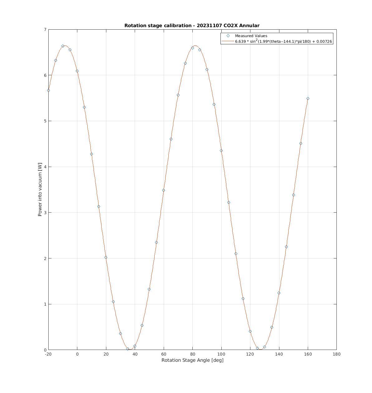
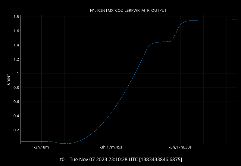
TJ, Camilla. After we found both CO2 output powers have been changing since the timing master swap 74025, we recalibrated the CO2 rotation stages this morning ~ 16:20UTC. Last done in September 72961.
Followed the README.txt file in /opt/rtcds/userapps/release/tcs/h1/scripts/RS_calibration/. We did this with annular masks in. I'd previously tried this without using the matlab fitting code and hadn't been able to make a good fit.
Maximum power measured out of each laser:
| Annular Mask | Central Mask | |
| CO2X | 6.6W | 3.8W |
| CO2Y | 5.5W | 3.7W |
Plot attached, Aidan noted that we expect to get more power through the central mask than annular. We plan to check the mode matching going into the masks in the next couple of weeks.

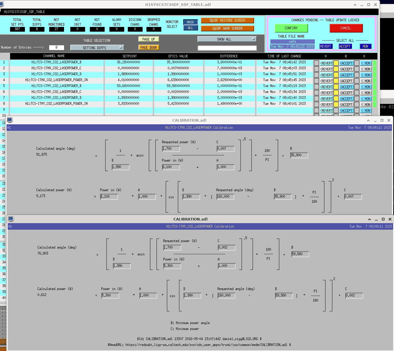
TJ noticed some strangeness with the CO2X rotation stage not going back to the same place, over ~minutes. Turned H1:TCS-ITM{X,Y}_CO2_LASERPOWER_FINEADJUST to False, as PSL RS uses. And re-tuned the attached calibration, this could do with more work but will leave alone as we are relocking.
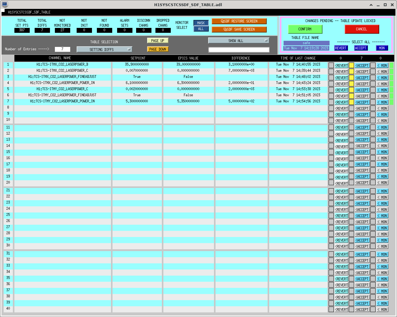
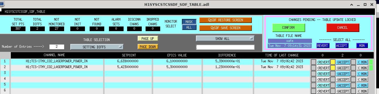
I've added some bootstrapping to the CO2 power guardians to approximate the adjusted power request after it reaches the initial request. This will only bootstrap on the way up, not when finding minimum power. Something that should be added is to not bootstrap if close enough, we've noticed the rotation stage will do some odd moves when very small angle changes are requested.
adjusted power request = (initial request)^2 / current power
This morning I remotely tweaked the beam alignment into the FSS RefCav using the 2 picomotor-controlled mounts in the FSS beam path. In looking at the reflected spot on the PSL quad display it was obvious the alignment had shifted since Jenne's tweak last Tuesday, but the TPD had increased from ~0.81 V to ~0.86 V, indicating the the beam alignment was getting closer to where it was the last time I adjusted it on the table; this is also an indication that I could likely get more TPD with another alignment tweak. With the IMC OFFLINE I started with a TPD of ~0.86 V, and when I ended the TPD was ~0.91 V. For future reference, I had to walk the beam in mostly the vertical direction, but some horizontal as well; I moved up/left on mirror M23 (1st picomotor-controlled mount, RefCav A on the picomotor MEDM) and down/right on mirror M47 (the top RefCav periscope mirror and 2nd picomotor-controlled mount, RefCav B on the picomotor MEDM). With the IMC back ONLINE, the FSS RefCav TPD is ~0.89 V.
TITLE: 11/07 Day Shift: 16:00-00:00 UTC (08:00-16:00 PST), all times posted in UTC
STATE of H1: Wind
OUTGOING OPERATOR: Ibrahim
CURRENT ENVIRONMENT:
SEI_ENV state: MAINTENANCE
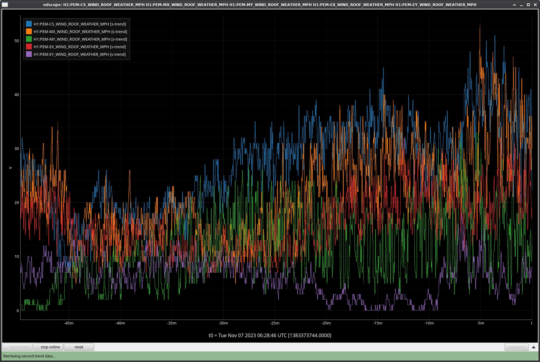
Wind: 17mph Gusts, 8mph 5min avg
Primary useism: 0.06 μm/s
Secondary useism: 0.37 μm/s
QUICK SUMMARY:
Detector is DOWN and in WINDY due to high wind. Taking us to Preventative Maintanance for today's maintanence.
Looks like at 14:32UTC the wifi at LVEA, EX, and EY went down and haven't come back. Waiting on a CDS person to start looking into it.
Logs:
Sorry I was slow getting the WAP IOC running again on opslogin0 this morning. This has prompted me to move this EPICS IOC from opslogin0 to the main cdscds0 server so it will run continuously.
With maintenance only an hour+ away and the wind still higher, I've request ISC_LOCK to IDLE and brought SEI_ENV to Maintenance. I've left the Observatory Mode in WIND for now to account for some of the past few hours, and we can switch it to maintenance shortly.
Workstations were updated and rebooted. OS packages were updated. Conda packages were not updated.
Was alerted at 8:49UTC.
Guardian was having trouble with automatic initial alignment due to ALS_XARM being stuck at CHECK_CRYSTAL_FREQ with no valid state to jump to afterwards.
I hit "Load" and restarted initial alignment and waited until Guardian got past this stage in initial alignment, which happened around 50 minutes later at 9:30.
Things seem to be working now so I set guardian/IFO_Notify back to self-managed and expect to be called again if we get stuck for any other reason.
The CHECK_CRYSTAL_FREQ state in ALS_ARM's (XARM) code which checks on the H1:ALS-{ARM}_FIBR_LOCK_BEAT_FREQUENCY channel threw an index error which I thought I had handled but apparently not, so I added a try-except error handler to the loop where it checks the list of frequency spots to check index and I also added a sleep timer because it looks like it fixed the issue and had the beatnote within tolerance twice but then kept going and changing the frequency which worsened the beatnote and brought it out of tolerance, it just flashed through it? Hopefully the sleep timer will help with this, I'll think more about how to make the code better.
TITLE: 11/07 Eve Shift: 00:00-08:00 UTC (16:00-00:00 PST), all times posted in UTC
STATE of H1: Lock Acquisition
INCOMING OPERATOR: Ibrahim
SHIFT SUMMARY: Locked for most of the evening, but high winds have kept H1 down for the last hour and a half.
Wind speeds aren't quite as bad as they were, so I'm going to set H1 to try locking as I hand off to Ibrahim for the night.
LOG:
No log for this shift.
Lockloss @ 06:22 UTC - assuming this is due to the suddenly high wind speeds. Currently seeing gusts over 50mph and the wind is loud against the outer walls of the control room.
First thing I noticed before the lockloss was PRG getting very unstable and ASC control signals working harder.
Unfortunately it doesn't look like the winds will be calming down much tonight according to the forecast.
Corner station wind spiked to 55mph a minute ago; holding H1 in DOWN for now as it's not having any success locking ALS.
State of H1: Observing at 158Mpc
H1 has been locked and observing for just over 4 hours. EX VEA temperature has come back to normal.
The first page of the figure shows that there was a gain of 2 or 3 Mpc when the EX HVAC was shut down. The second page shows DARM for this series of tests, with the most evident difference in the 38-45 Hz range. We have already realized much of the potential improvement with damping of the cryobaffle by significantly reducing the noise from fans in the 4 Hz region over the last couple of months and reducing the 52 Hz peak over the weekend, so I dont expect more than a couple of Mpc improvement with damping.
EX HVAC (fans, chillers cw pump) on-off tests:
Start shutting down: 20:00
Start turning on: 20:15
Start shutting down 20:30
Start turning on: 20:45
Start shutting down: 21:00
Start turning on: 21:15
FAMIS 26261, last checked in alog 73927
Fans have been turning on and off more than usual because of Robert's recent HVAC tests, but the noise levels of each fan look to be nominal and within range.
FAMIS 19967
pH of PSL chiller water was measured to be between 10.0 and 10.5 according to the color of the test strip.
FAMIS 20001
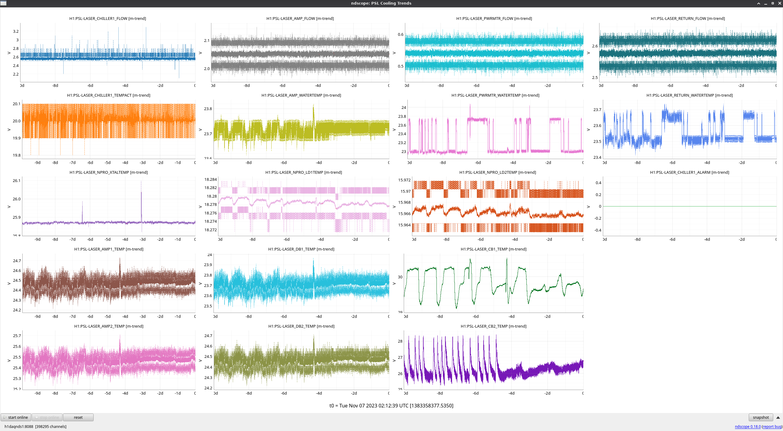
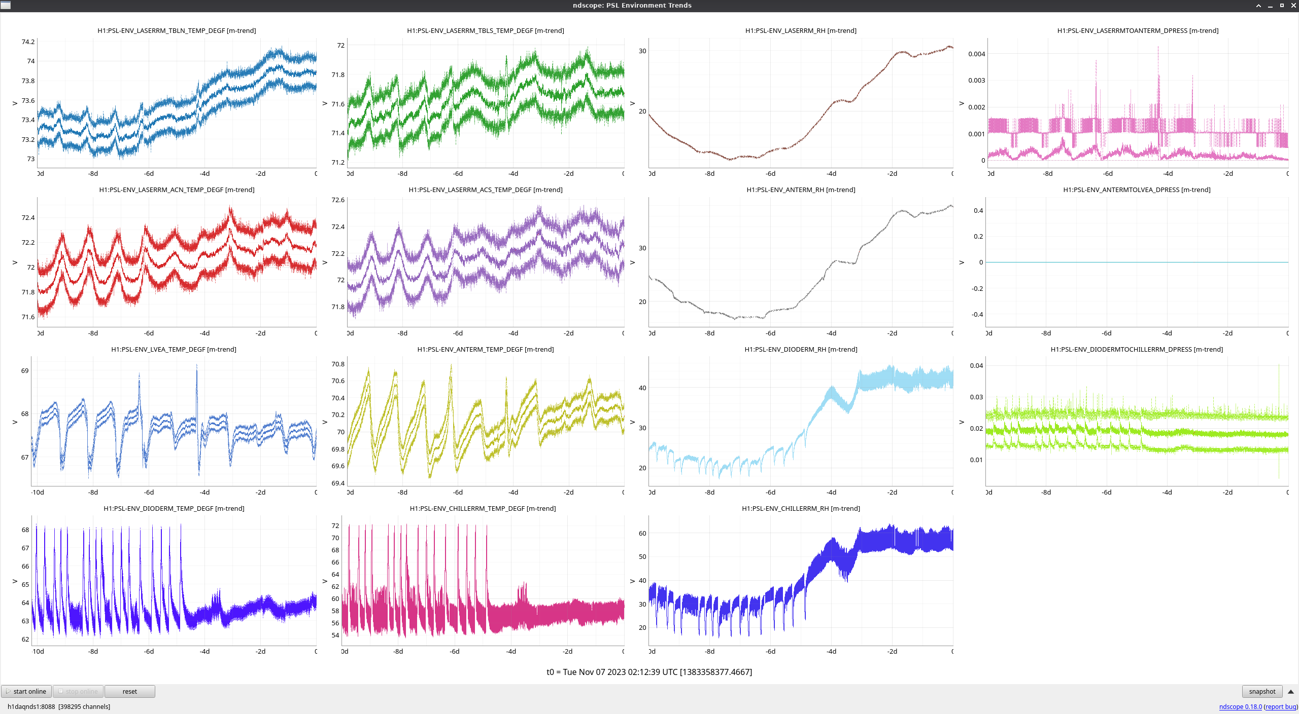
There's been a slight increase in temperature and humidity over the past week seen in the laser, ante-, chiller, and diode rooms, but not the LVEA.
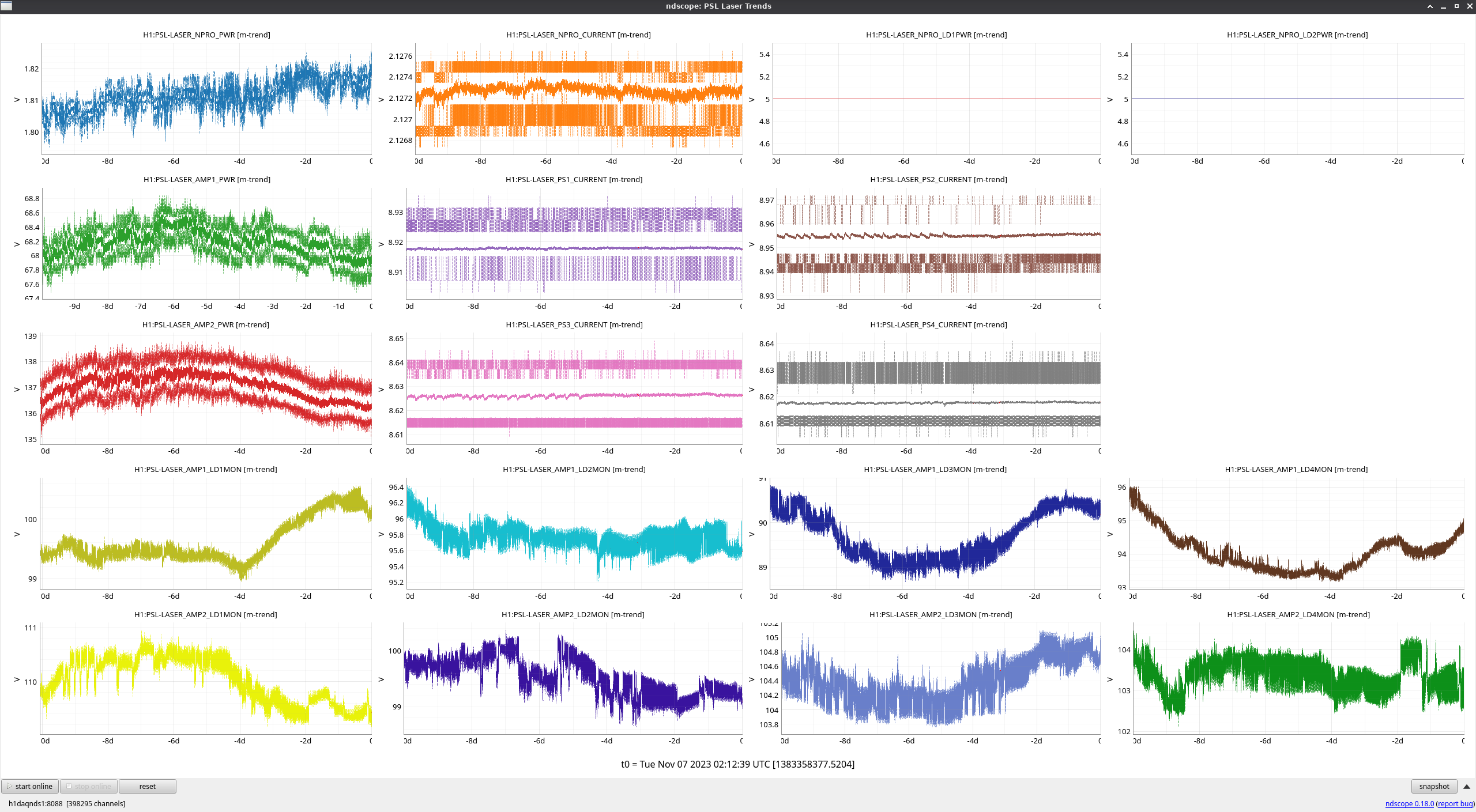
The output power for the NPRO has been slowly trending upward, but the output for both amps have been trending down.
TITLE: 11/06 Eve Shift: 00:00-08:00 UTC (16:00-00:00 PST), all times posted in UTC
STATE of H1: Lock Acquisition
OUTGOING OPERATOR: TJ
CURRENT ENVIRONMENT:
SEI_ENV state: CALM
Wind: 22mph Gusts, 18mph 5min avg
Primary useism: 0.04 μm/s
Secondary useism: 0.26 μm/s
QUICK SUMMARY: H1 has just reached NLN and camera servos have turned on. Camilla and Naoki are checking on SQZ before we start observing.
Naoki, Camilla
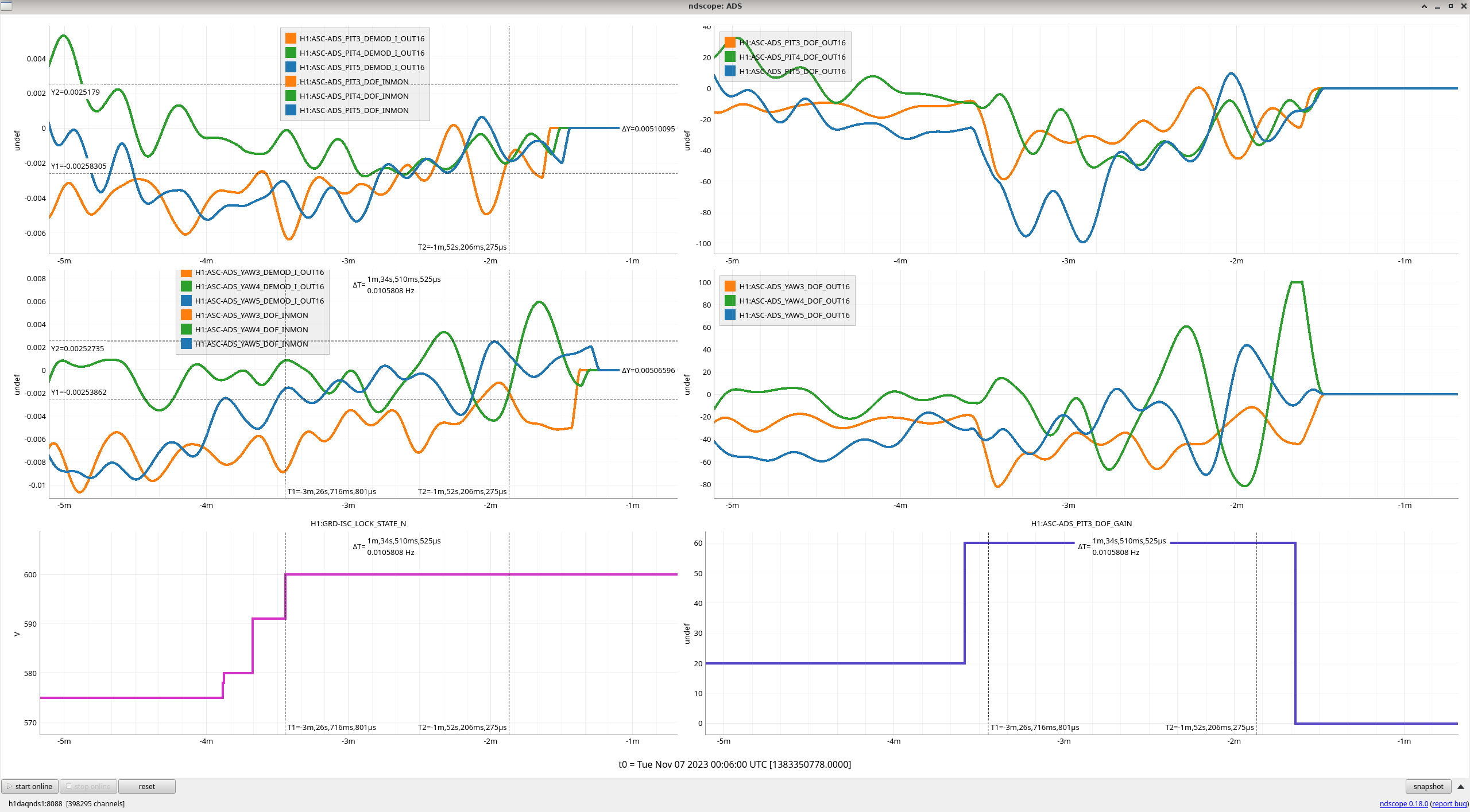
After noticing that it has been taking >20 minutes for the ADS servos to converge once we are at NLN 73842, Jenne suggested increasing ADS gains by a factor of 3 once we are close to NLN (after TRANSITION_TO_ETMX).
After this afternoon's 22:52UTC lockloss, Naoki edited lscparams and CAMERA_SERVO.py to increase the ADS gains from 20 to 60 in the TURN_CAMERA_SERVO_ON state of CAMERA_SERVO guardian. This state is only requested in ADS_TO_CAMERA state of ISC_LOCK, where it should be safe to increase gains. We'll plan to watch this first relock.
Motivated by interested results from Sheila's ESD tests last week (LHO:73913) and Gabriele finding that there is some nonlinear noise coupling in ETMX L3 from <4Hz to 15-25Hz in DARM (LHO:73937), I've started taking a closer look at the DARM loop to 1.) reduce ETMX L3 actuation below 4Hz (nominally by increasing L1/L2 actuation at low frequencies) and 2.) to have the UIM stage roll off more aggressively, similar to what LLO has had in place since O1 (see for example page 10 of G1501372 and page 11 of G2000149 ). I'm uploading the "DARM critique" generated by pyDARM for H1 based on report 20231027T203619Z. This is still a work in progress; I'm just leaving these plots & links here for my own future reference.
Tagging CAL.
As was briefly mentioned in alogs 73853 and 73917, I injected into thermistor 2 (hot one which is directly mounted on the compression ring of the OM2 mirror) and thermistor 1 (cold one mounted on the back of the T-SAMS structure) independently, and measured the transfer fucntion from the injection to DCPD-SUM (and some other TFs).
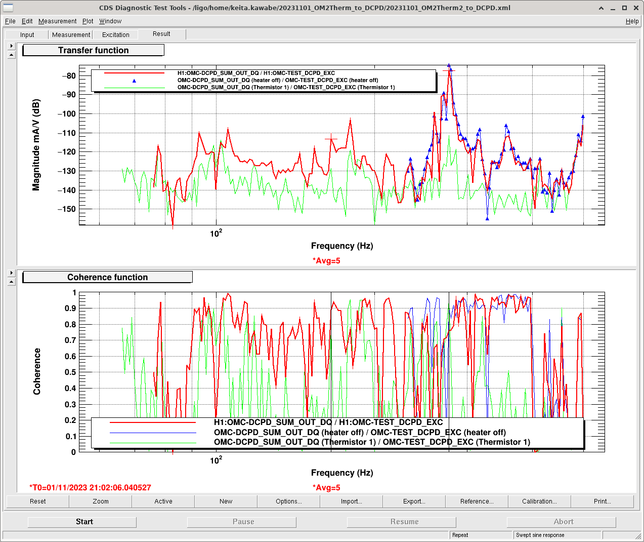
All traces in the attached show the transfer function and coherence from OMC-TEST_EXC (calibrated to the voltage across the Thermistor) and DCPD_SUM (in mA) when H1 is in high power. Red is the injection into Thermistor 2 (hot one), green is into Thermistor 1 (cold one), both while the heater was ON. There are many peaks, most notably the one centered at around 277Hz (that's where CW people observed the most problematic comb structure) but there are others like 78, 93, 105, 144, 154, 166, 314 and 356Hz with good coherence.
The coupling is actually very small for broadband noise, it's only problematic for lines like we've experienced. For example, even if we take the peak at 277Hz (-75dB = 1.8E-4 mA/V) for Thermistor 2, in order for the voltage noise to be comparable to e.g. the shot noise for 40mA DC (~1.1E-7 mA/sqrtHz), the voltage noise should be ~600uV/sqrtHz (because 1.1E-7 [mA/sqrtHz] / 1.8E-4 [mA/V]) at 277Hz, which is a big number.
Thermistor 1 TF amplitude is smaller by more than 30dB than Thermistor 2 measured at around the 277Hz peak. This cannot be explained by the current difference due to lower resistance of the hotter thermistor (thermistor 1 is 7.41k, thermistor 2 is 4.08k, measured on the floor). It should be the location of the thermistor. FYI Thermistor 2 is mounted on the compression ring of the T-SAMS and is therefore much closer to the mirror than Thermistor 1 that is mounted on the back.
Within the resolution of this measurement, frequencies of Thermistor 1 peaks that are visible do match with Thermistor 2, but the resolution is not great (~2Hz at around 277Hz) so it's not clear if we're looking at the same resonance driven by different thermistors, or if this is actually two different resonances, each belonging to one thermistor but not the other.
Blue is the injection into Thermistor 2, but this time the measurement was done immediately after the heater was turned OFF. I only measured down to 220Hz or so, but anyway I see no real difference between the blue and the red. This means that the magnetic field formed by the heater loop around the mirror is NOT relevant for the coupling. Since our experience was that the comb was NOT there while the OM2 was cold, maybe the coupling is dependent on the tightness of the compression ring.
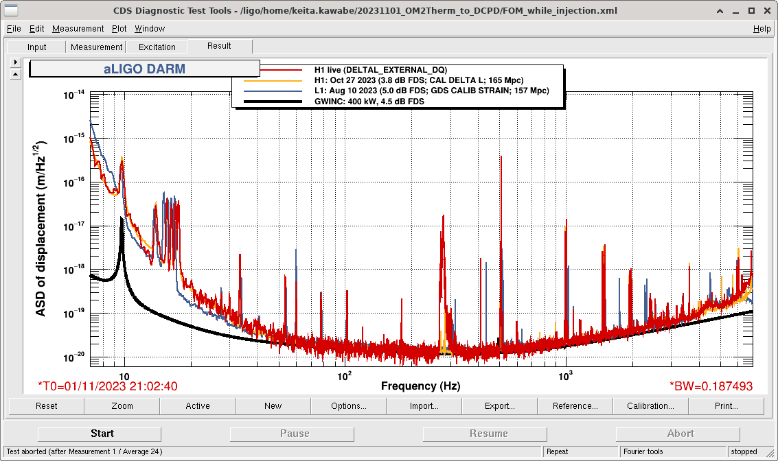
Injection amplitude was constant (A=8000 i.e. 16000cts pp sine wave for all frequencies, corresponding to ~4.9Vpp across the thermistor), and I was making huge lines in DARM (2nd attachment).
After the measurement, all breakout boards and temporary cables and handheld voltage reference and things were disconnected from the system (but were left on the work table by HAM6, I'll pick them up during the next maintenance). EXC cable was connected back to the DCPD whitening, and Beckhoff cable was connected back to the OM2 heater driver.
Do you see the responce in the DCPDs without the light i.e. is the coupling purely electric ?
No, without any light on the DCPD there were no lines on it.
We also tested direct coupling into the OMC PZT by putting the OMC half off the fringe using a direct laser beam. No signal as well.
We've done three measurements assess OMC loss, but we've found that there's something weird about DCPD transient response (will attach another alog, but it seems as if something is railing inside the chamber, or maybe the OMC DCPD inductor is responding nonlinearly causing some kind of soft saturation, or maybe it's just a whitening-dewhitening mismatch).
Because of this, Measurement 1 below is suspect, Measurement 2 is definitely OK, Measurement 3 is probably OK too.
Analysis will come later.
Throughout the measurement, RF sidebands (9, 45 and 118) were OFF, H1:OMC-DCPD_A_GAINSET and B were set to low (a factor of 10 smaller than nominal), and IMC-PWR_IN was 10W.
Measurement 1. Scan OMC PZT and measure the MM loss.
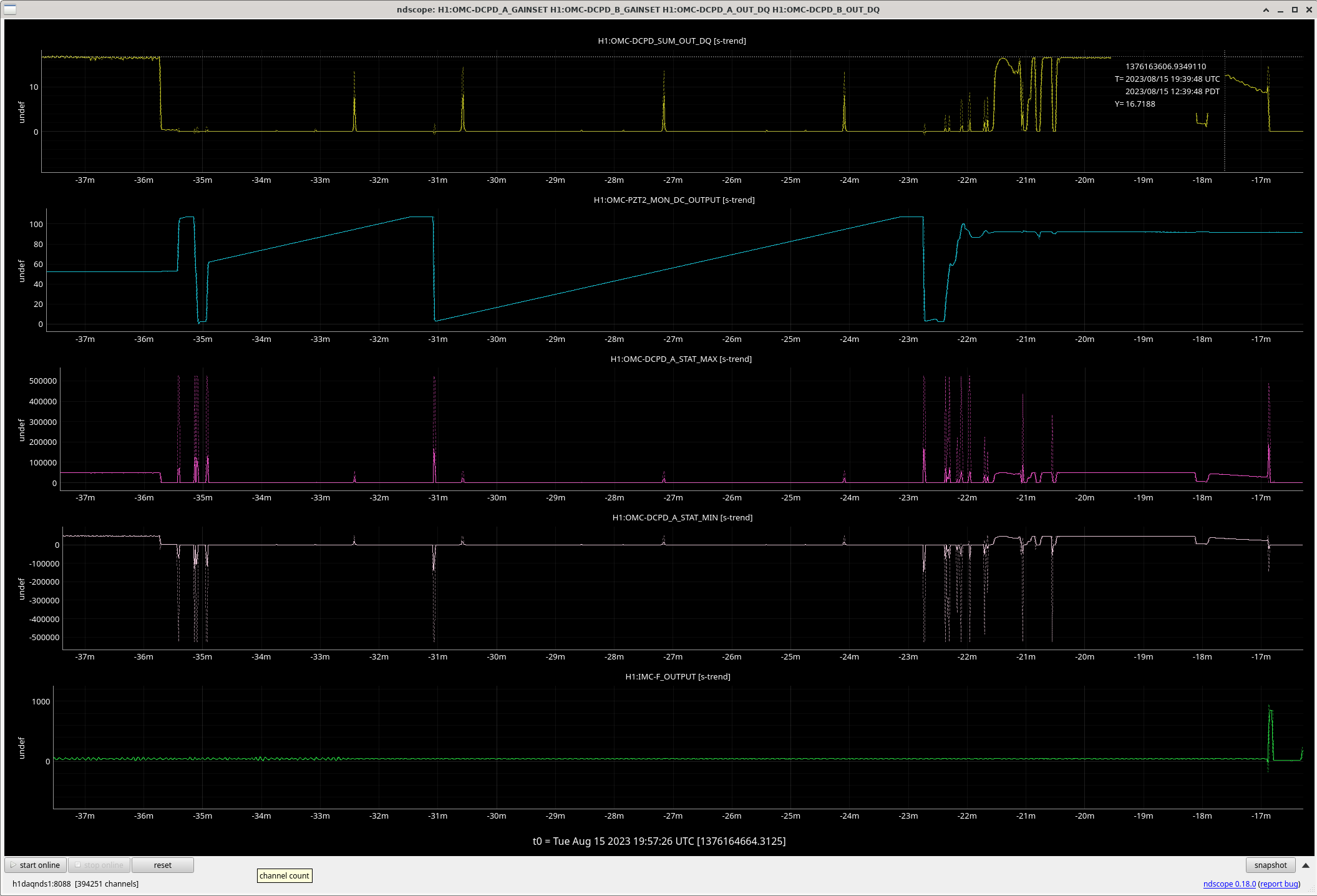
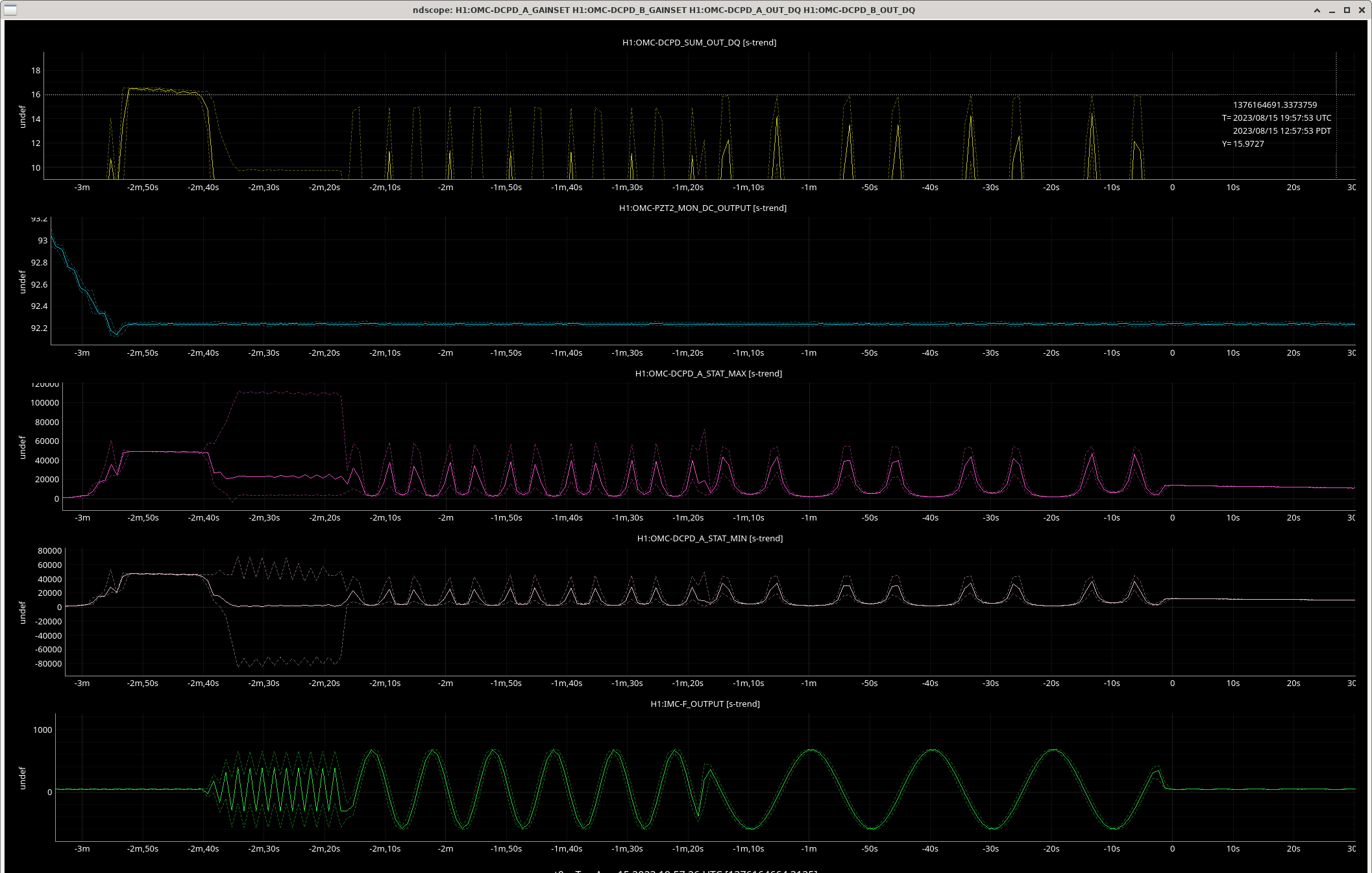
Lock OMC, align OMC reasonably well, unlock, scan the PZT slowly. The best scan is between 19:26:25 and 19:34:44 UTC (t=[-31m,-23m] in the 1st attachment).
"Align reasonably well" was a challenge as we were using the OMC QPD for OMC ASC, changing alignment meant changing QPD offset, and doing so frequently railed OMC suspension. While changing the offsets, maximum DCPD_SUM I could reach was 16.9, but I kept bumping OMCS so I gave up (sensor correction was off for the first half of this effort and that didn't help). In the end, usable data was obtained with default offset that gave us ~16.6 when locked, but we know that that was NOT the best alignment.
As you can see, the peaks in DCPD_SUM during the scan are all about ~14, much smaller than 16-something. (At t=-36m, the OMC was held at resonance and DCPD_SUM was ~16.6. After the scan at t=-20m, DCPD_SUM was ~16.45. So the alignment drift wasn't much of a problem.)
It turns out that we had to scan slower than this even though this was REALLY slow (~8 minutes for one cycle) and/or lower the laser power.
Measurement 2. OMC throughput.
Lock the OMC to 00 resonance (19:37:27-19:38:28 UTC, roughly t=[-20m, -19m] on the 1st attachment).
Measure DCPD_SUM, input power (via ASC-OMC_A and ASC-OMC_B SUM) and reflected power (via OMC-REFL_A).
With the same alignment into OMC, find the time where the OMC was off-resonance (DCPD transmission was minimal 19:25:58-19:26:20 UTC), and measure DCPD_SUM, input power and reflected power.
Calculate the throughput.
Measurement 3. OMC Finesse
I roughly kept the OMC at resonance by adjusting pzt voltage. DCPD_SUM was slowly drifting but it was about 16.0.
I started injecting into PSL frequency with an amplitude of ~+-600kHz (1.2MHzpp) via IMC-L_EXC. I slowed down the injection frequency until the peak value gets back to 16.0. (Second attachment.)
Best scan data is obtained 19:56:20-19:57:20 UTC.
OMC DCPD transient response
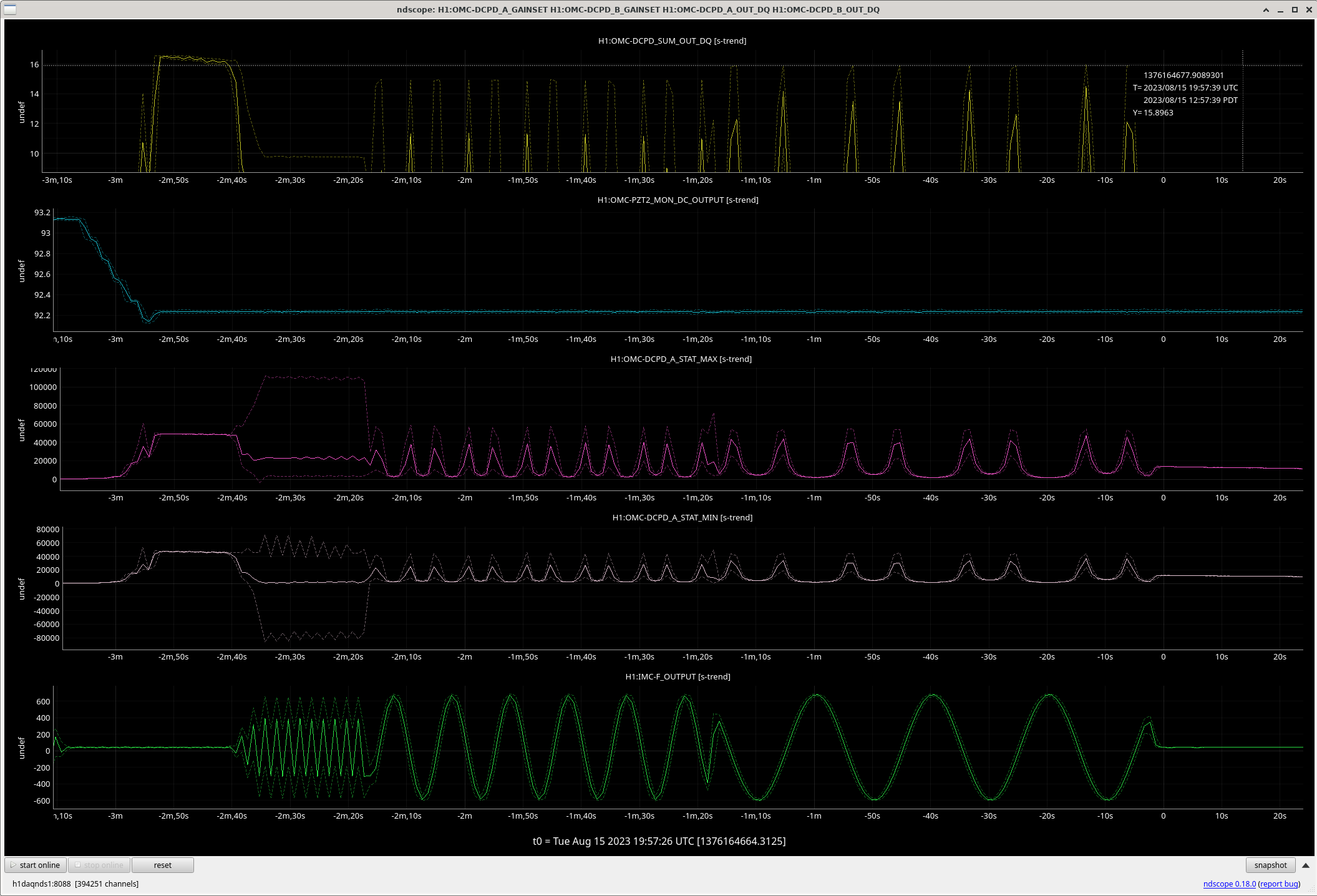
Let's see the 2nd attachment of the above alog (which is attached again).
At t=[-2m40s, -2m20s], nothing is railing at ADC. You can tell that as ADC saturation means that OMC-DCPD_A_STAT_MAX and/or OMC-DCPD_A_STAT_MIN hit +-512k (MAX only went to 120k and MIN only went to -80k in this case).
However, note that the DC value for MAX and MIN during the time OMC was kept on resonance were about 48k and 47k, respectively. The fact that MIN went to negative 80k and MAX went to positive 120k means that the transient response was huge.
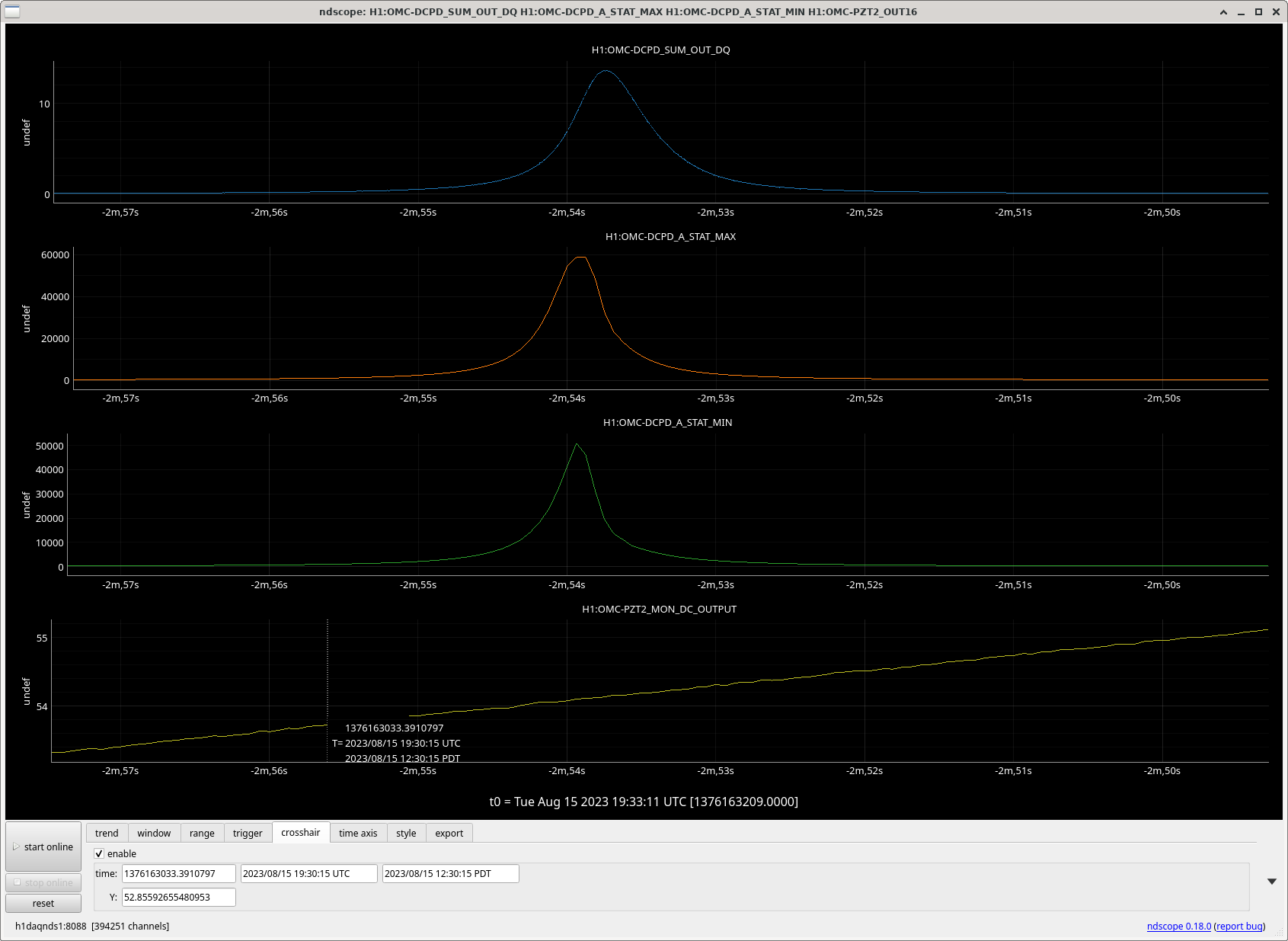
Even though it was huge, if nothing was railing nor saturating, you'd still expect that the peak height in DCPD_SUM is the same as when the OMC was kept on resonance, but clearly that's not the case. At first when the scan was fast the peak value was maybe 60% of what it should have been, and as I slowed down the scan the peak gradually went back to ~99% or so.
In the case of the PZT scan, we're talking about the slow velocity where each 00 peak is ~0.6sec wide (and that was too fast, we should have reduced the laser power, anyway see 2nd attachment).
Where does the mismatch come from?
A simple whitening-dewhitening mismatch? Is something railing inside the chamber, or maybe soft-saturating because of large transient (e.g. big coil?). I think we need a help from Hartmut.
I'm using Keita's times from the OMC visibility measurement above to runthe script described in 73873, and using the dark offset times from that alog as well. This time includes more higher order mode content, and slightly higher overall efficiency, than the time in 73873, which is somewhat confusing.
Results:
Power on refl diode when cavity is off resonance: 22.764 mW
Incident power on OMC breadboard (before QPD pickoff): 23.207 mW
Power on refl diode on resonance: 2.081 mW
Measured effiency (DCPD current/responsivity if QE=1)/ incident power on OMC breadboard: 82.7 %
assumed QE: 100 %
power in transmission (for this QE) 19.187 mW
HOM content infered: 8.979 %
Cavity transmission infered: 91.712 %
predicted efficiency () (R_inputBS * mode_matching * cavity_transmission * QE): 82.676 %
omc efficency for 00 mode (including pick off BS, cavity transmission, and QE): 90.832 %
round trip loss: 685 (ppm)
Finesse: 392.814
assumed QE: 96.0 %
power in transmission (for this QE) 19.986 mW
HOM content infered: 9.099 %
Cavity transmission infered: 95.660 %
predicted efficiency () (R_inputBS * mode_matching * cavity_transmission * QE): 82.676 %
omc efficency for 00 mode (including pick off BS, cavity transmission, and QE): 90.952 %
round trip loss: 348 (ppm)
Finesse: 401.145
Tagging
- CAL (because of the suggestion that there's a mismatch between analog whitening and digital compensation for it [I doubt it]),
- CDS (because Ali James -- who was Hartmut's student that built up the in-vac transimpedance amplifier -- now has been hired as our newest CDS anlaog electronics engineer),
- DetChar (because understanding this transient behavior may be a clue to some other DetChar / GW channel related transient features, since Keita refers to studing *the* DCPDs -- the OMC DCPDs).