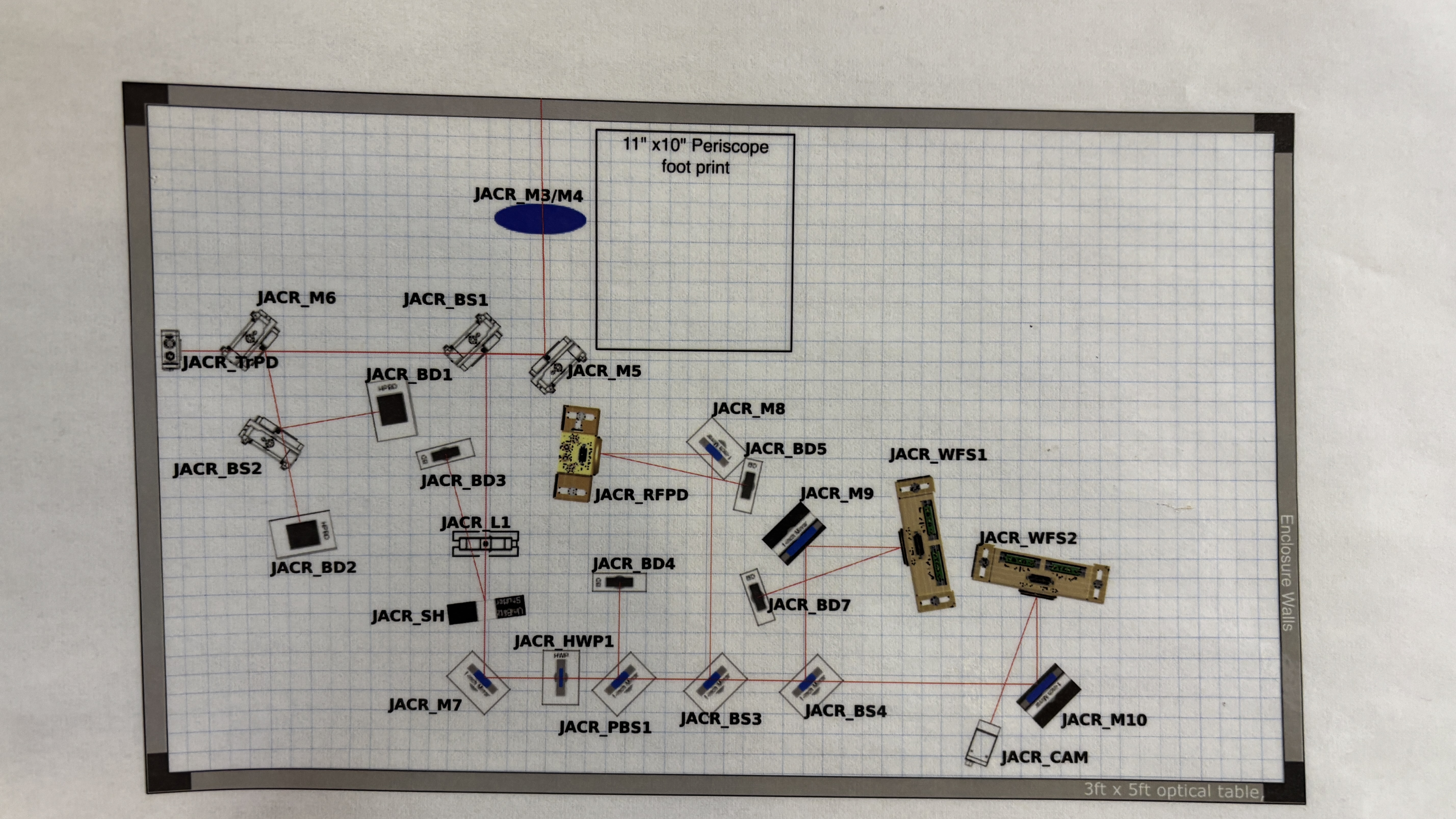
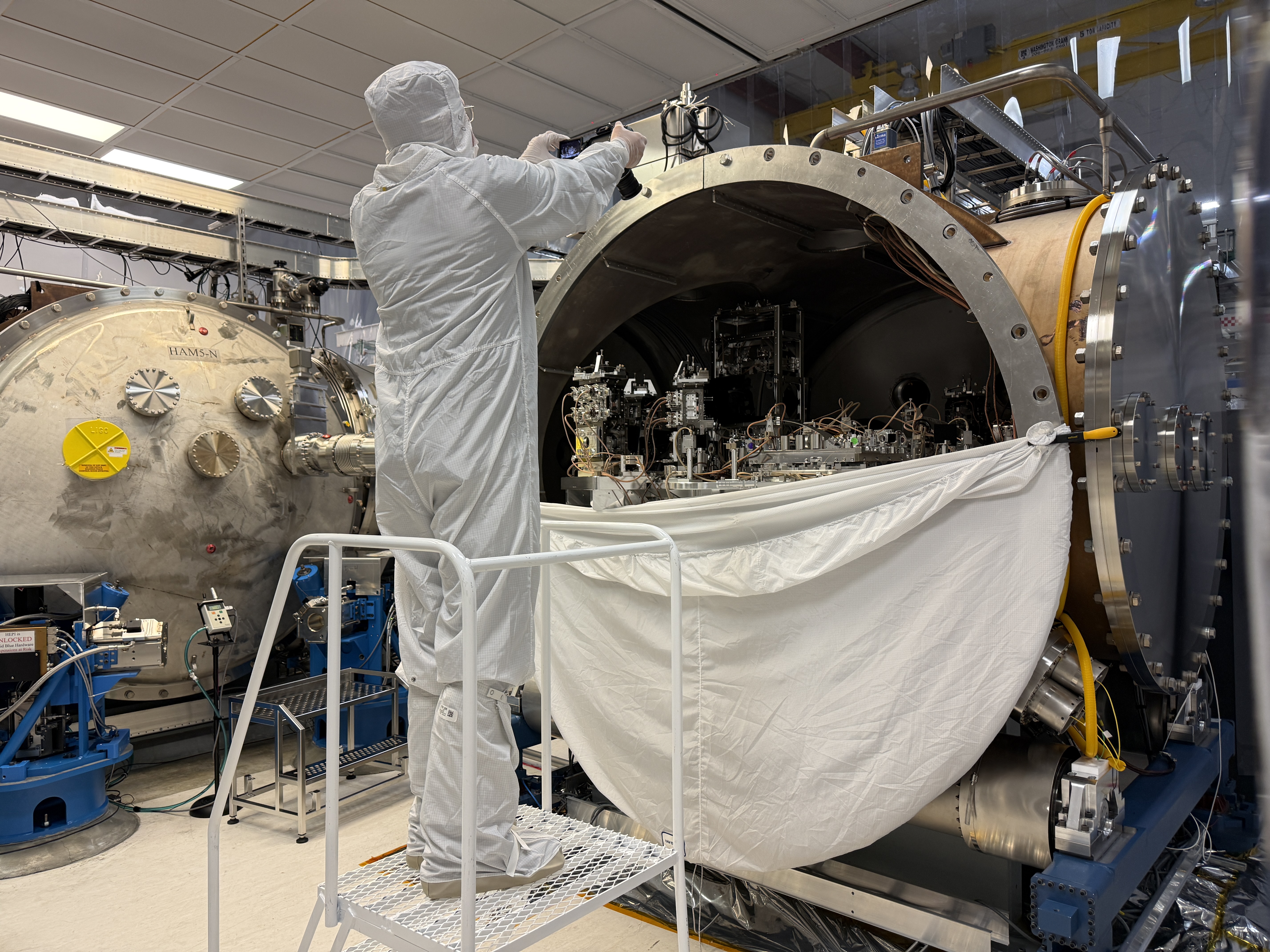
J. Kissel, J. Warner (with sage wisdom provided remotely by S. Koehlenbeck)
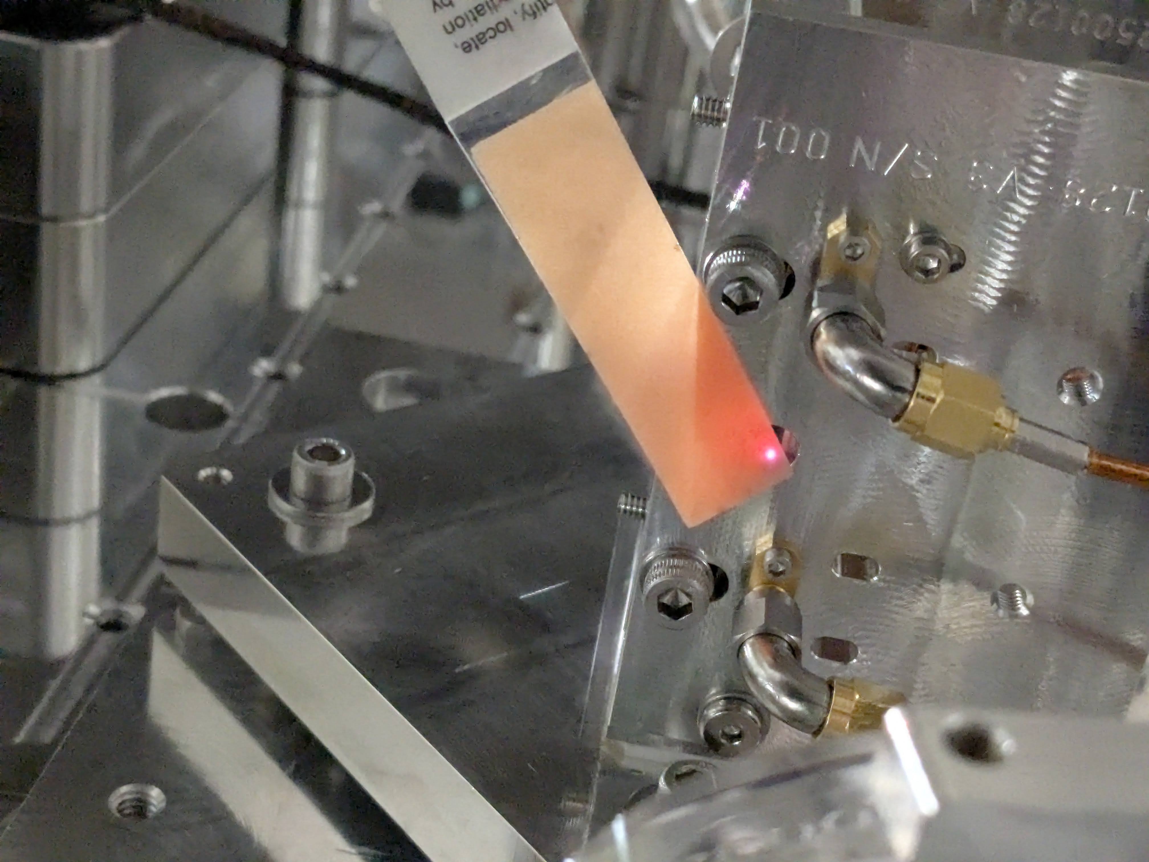
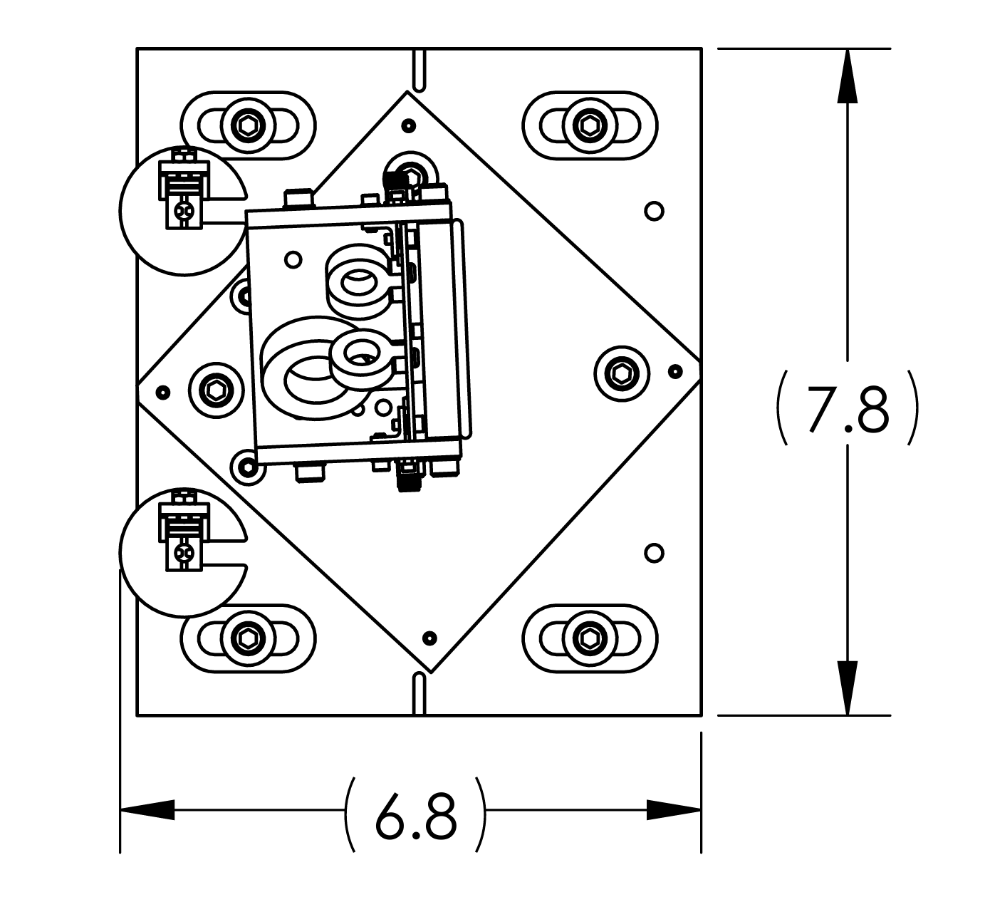
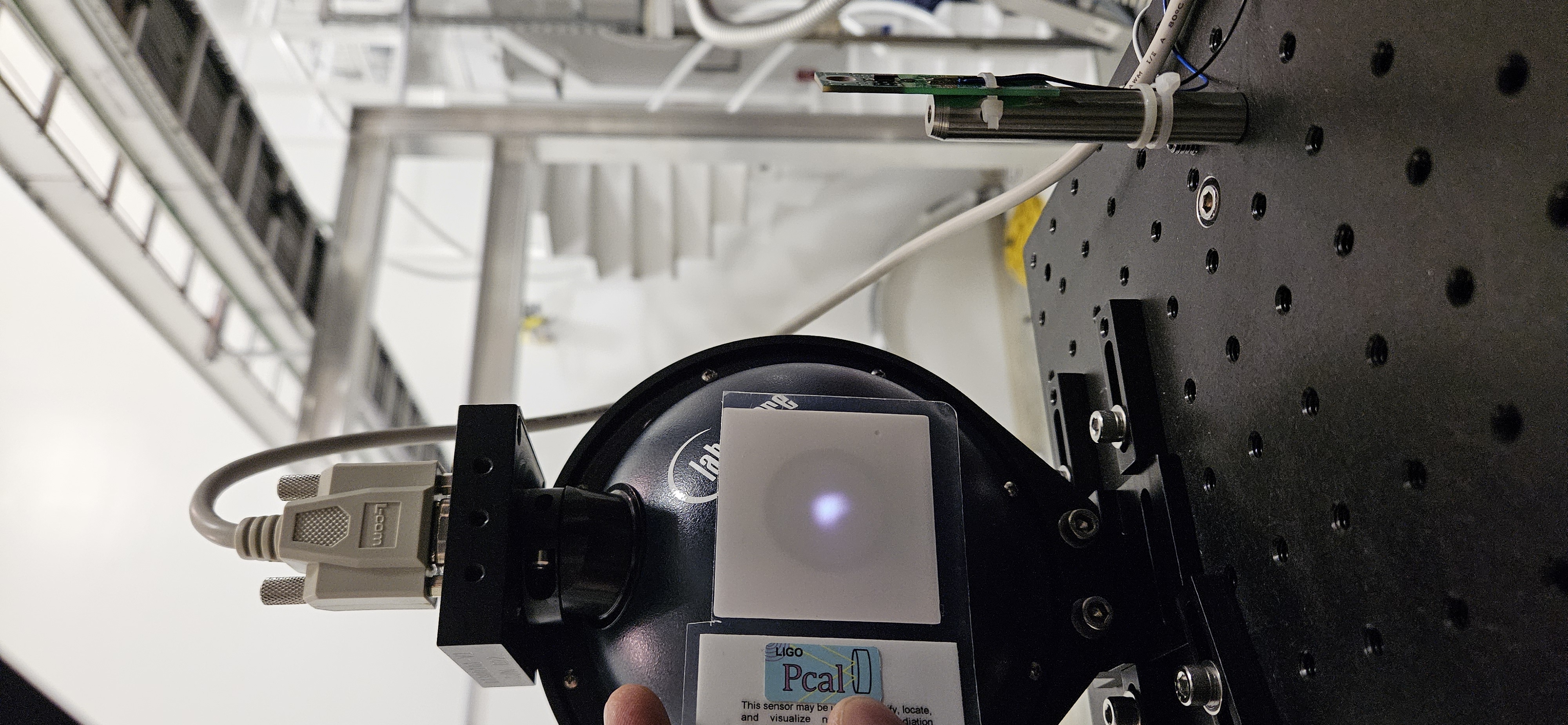
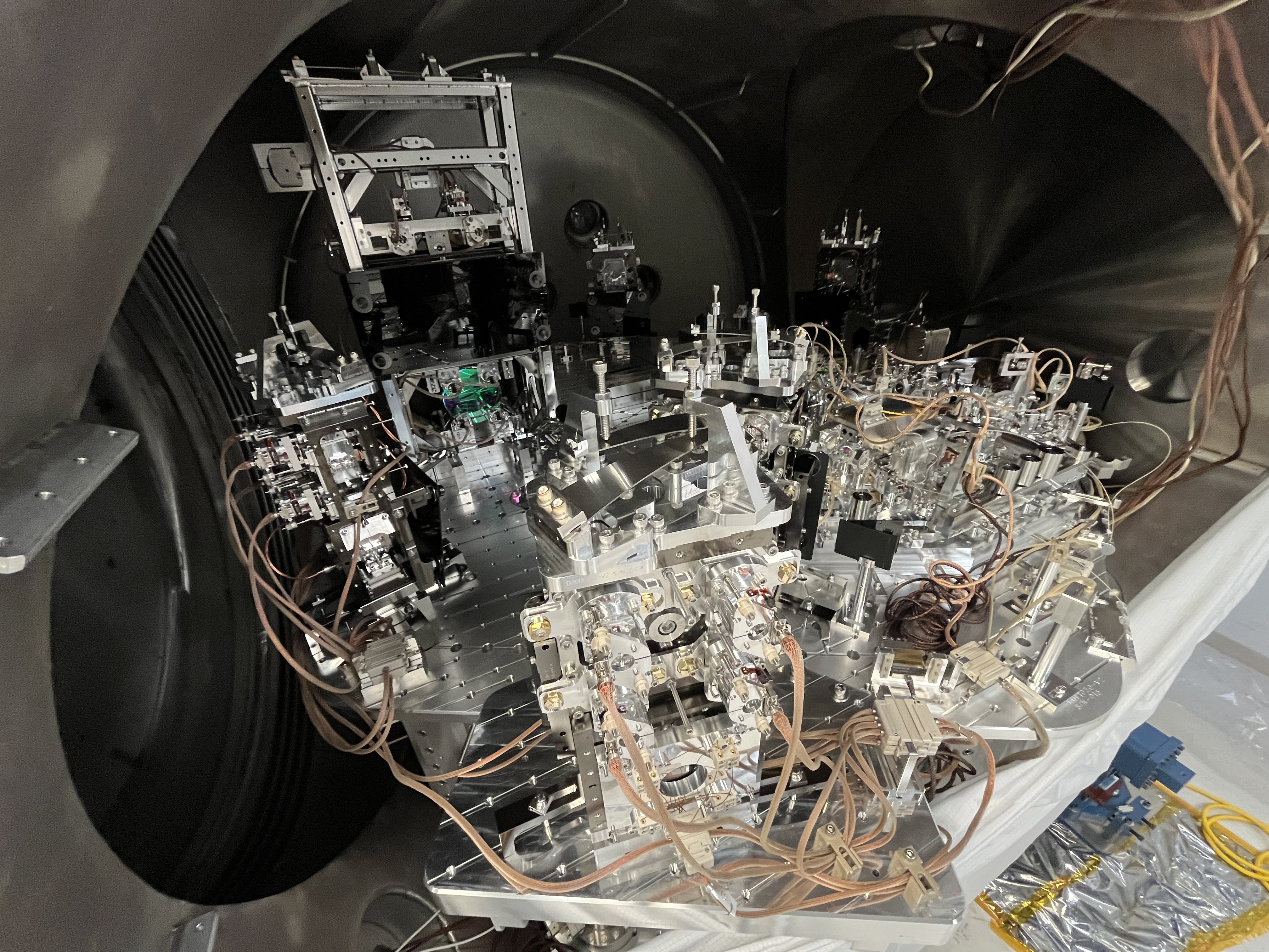
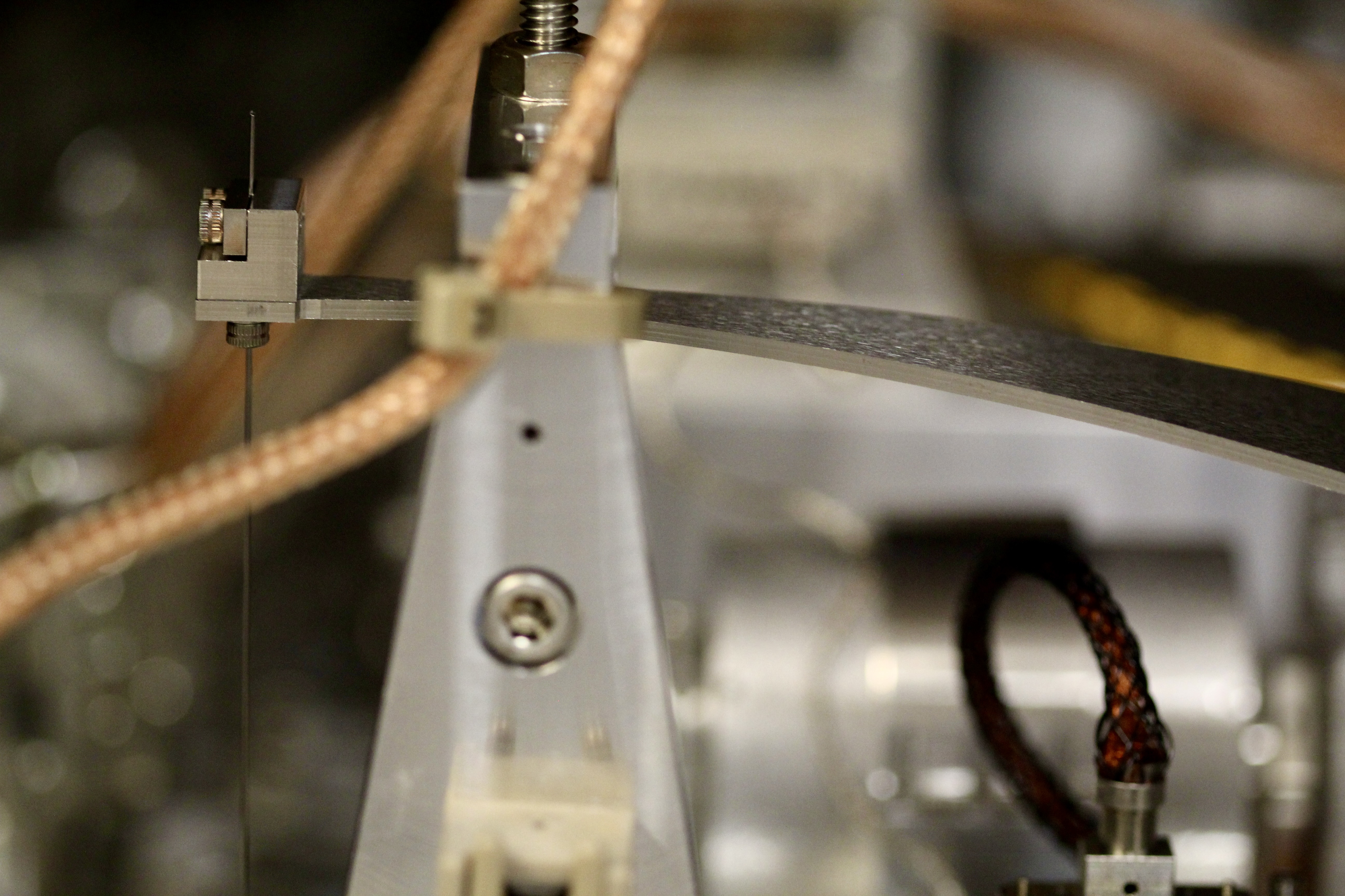
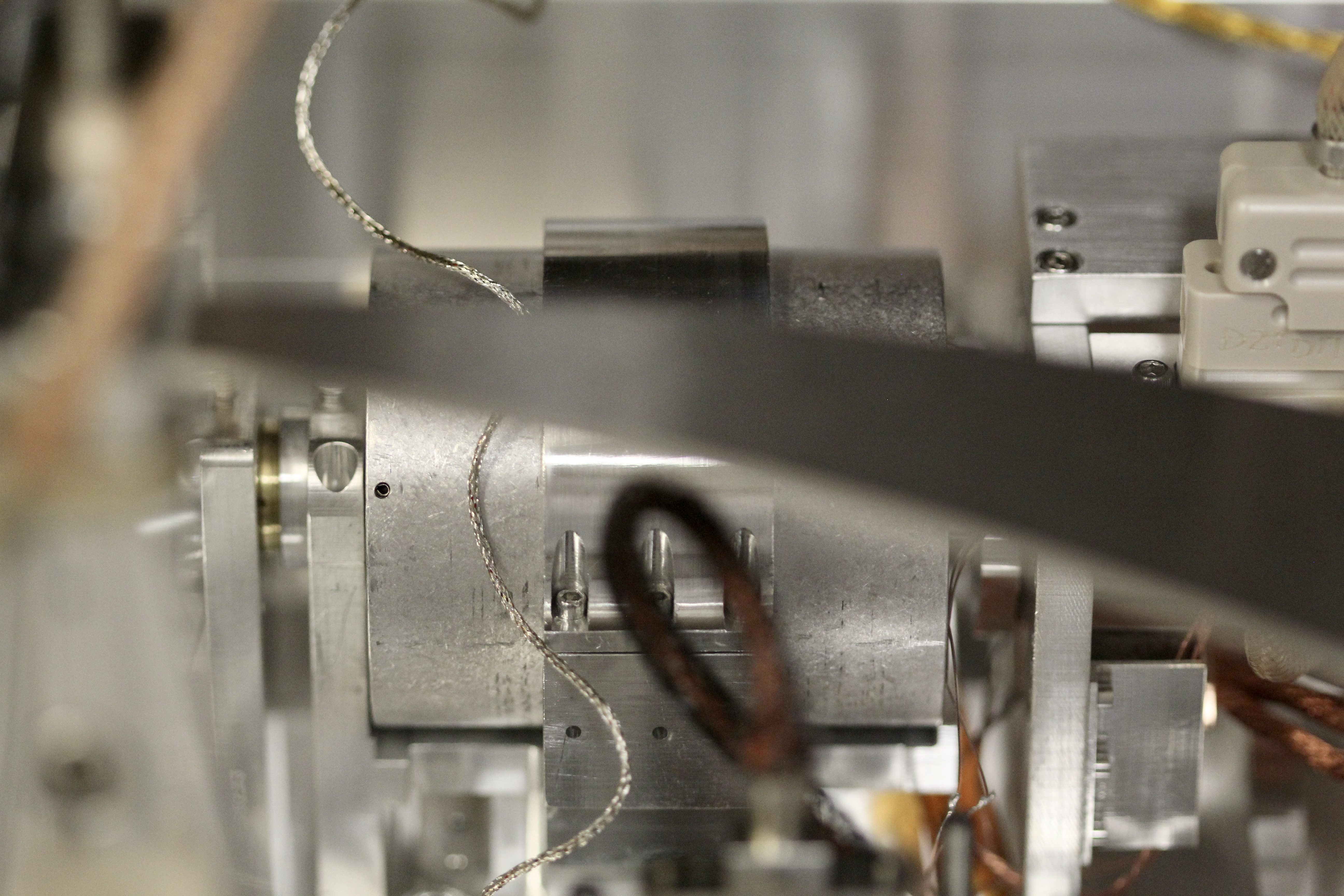
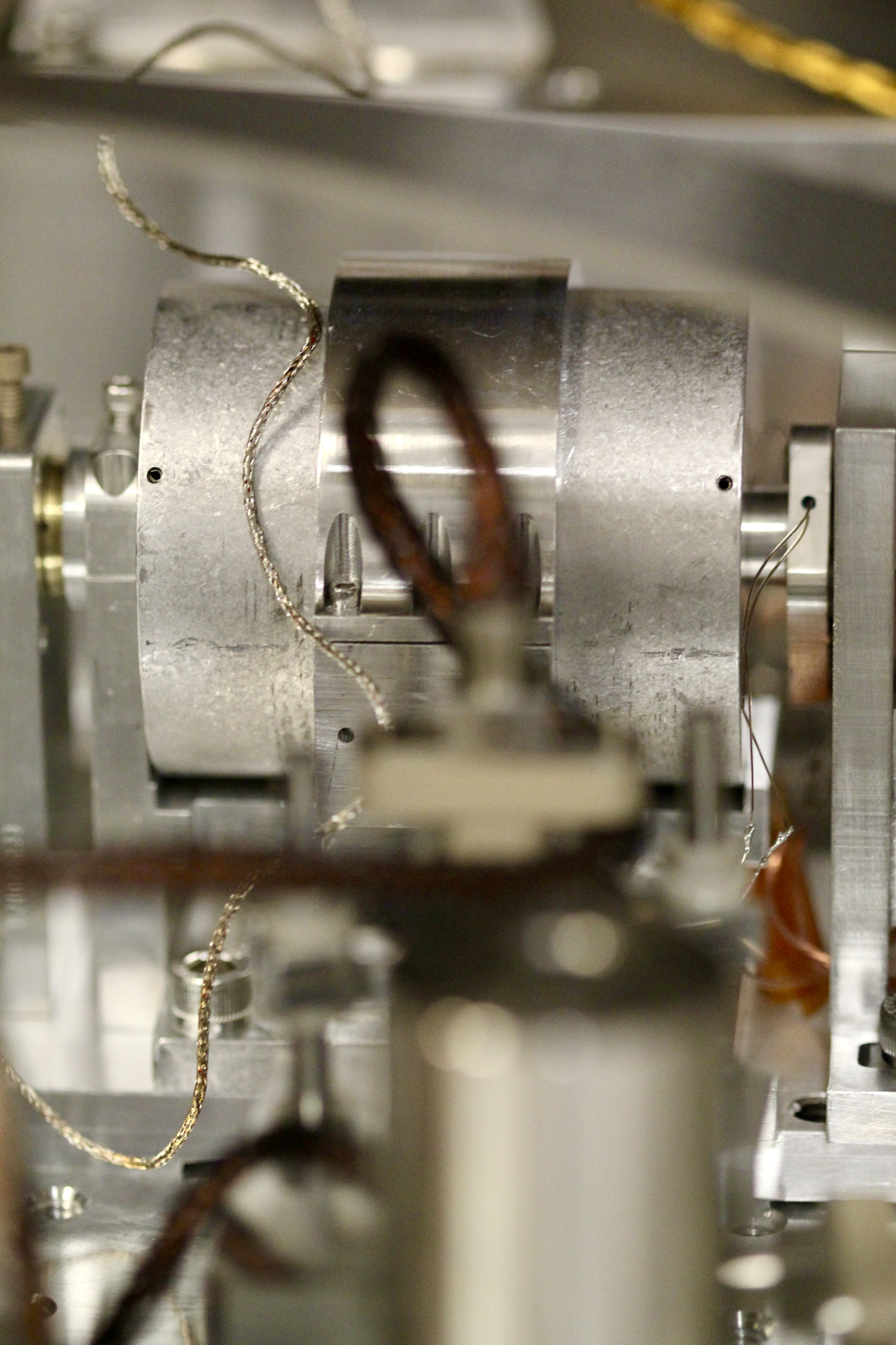
After mounting fiber collimator S0272503 within its predestined adapter ring into the actuator-less IXM100 mount (one of two from LHO:86299) -- creating a fiber collimator assembly (D2400146) -- we connected the integrated fiber patch cord of the fiber feedthru S3228003 (see LHO:89029) to the collimator.
With this final, "as it shall now be forever" integrated fiber-optic-to-free-space converter system for the SPI MEAS path, we want to adjust the collimator's lens position to achieve "optimal collimation;" having the waist of the beam at the fiber collimator. To avoid obnoxious factors of two mistakes, the variable w shall be used to refer to beam radii as a function of position, z, along the beam projection, and thus w0 shall refer to the beam radius at beam projection distance, z = 0. Whenever diameters = 2*radii are envoked, D, shall be used, e.g. the beam waist diameter shall be D0, and the beam diameter as a function of beam projection distance shall be D(z).
Previous attempts to adjust the lens position of the S0272502 collimator are described in LHO:84825 (dirty, using the AxcelPhotonics Butterfly Dioe Laser) and again in LHO:86350 (post-Class-B bake, also with AxcelPhotonics laser).
The method used in those entries was repeated:
(0) Set up a 1064 [nm] fiber-coupled seed laser, and markers of beam projection distances at z = [0.508 0.991 1.499 2.007 3.251 4.496 5.41] [m] (Roughly even half-meter points that one gets from "finding 1 inch hole position that gets you close to 0.5 [m] increments", i.e. z = [1'8", 3'3", 4'11", 6'7", 10'8", 14'9", and 17'9"])
(1) Calculate the expected beam diameter at furthest projection distance,
D(z = 5.41 [m]) = (2 * w0) * \sqrt(1 + (z / z_{R})^{2})
assuming
z_{R} = \pi * w0^{2} / \lambda,
\lambda = 1064-e9 [m], and
w0 = 1.05e-3 [m]
That works out to be D(z = 5.41 [m]) = 4073 [um].
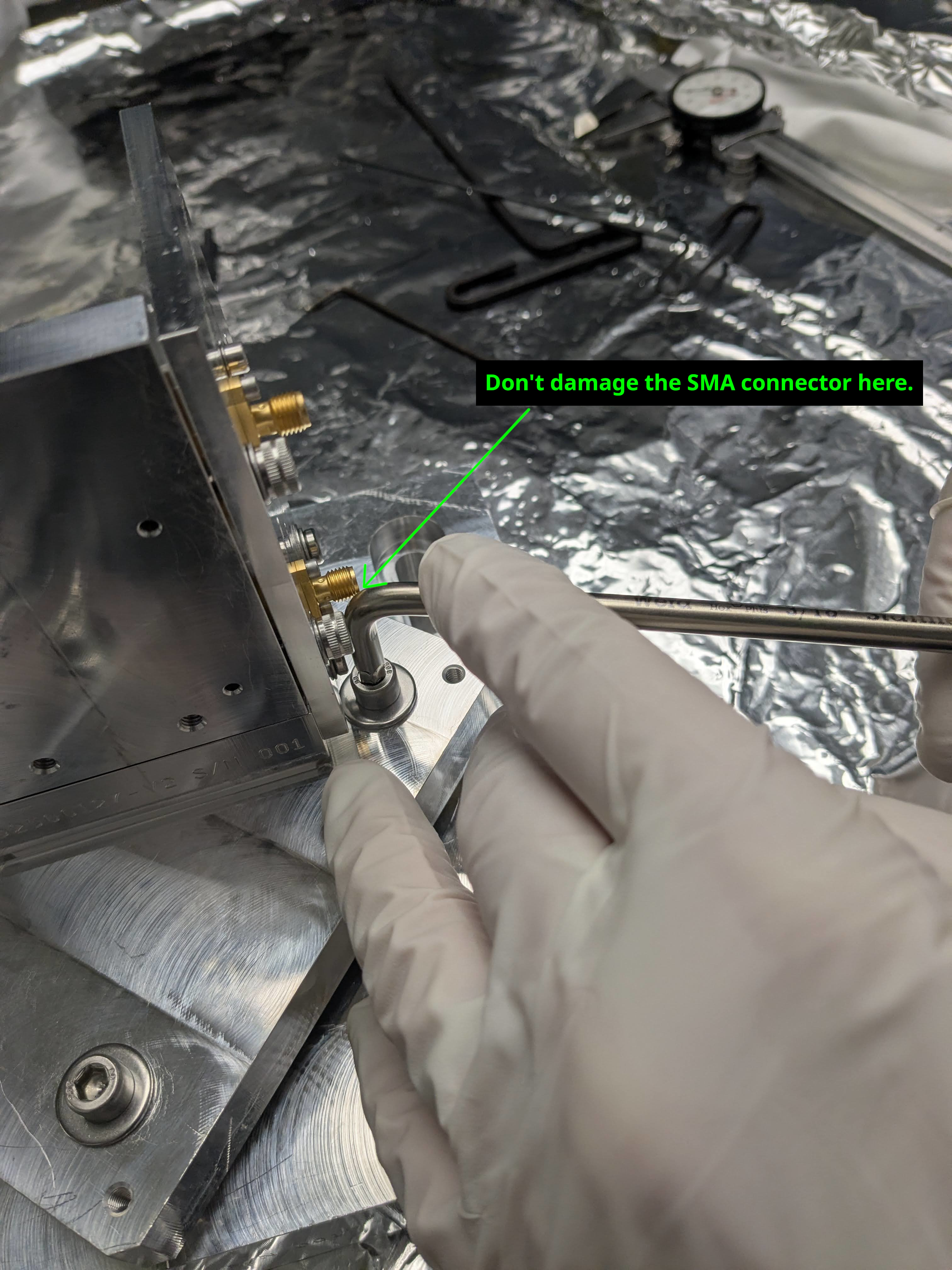
(2) Set up a beam profiler at the z = 5.41 [m] position (we again used the NanoScan, with the NanoScan-v2 software on a windows laptop), loosen the lens-position set screws with the tiny 1.2 [mm] flat-head screw driver, and use the proprietary SuK "eccentric key" cam adjuster to painstakingly iterate the position of the lens and gather a beam diameter measurement (using the "D4sigma" mean, waiting until the D4sigma standard deviation dropped below 1 [um]).
(3) Once happy that the X and Y beam diameters are within ~50 [um] of the target D( z=5.41[m] ) = 4073 [um], fix the lens position by re-securing its tiny set screws, and confirm the beam X/Y diameter remain acceptable.
(4) Move the beam profiler to each pre-designated beam projection position, z, and record the beam diameter.
We did a few extra things in our 2026-02-03 characterization as well:
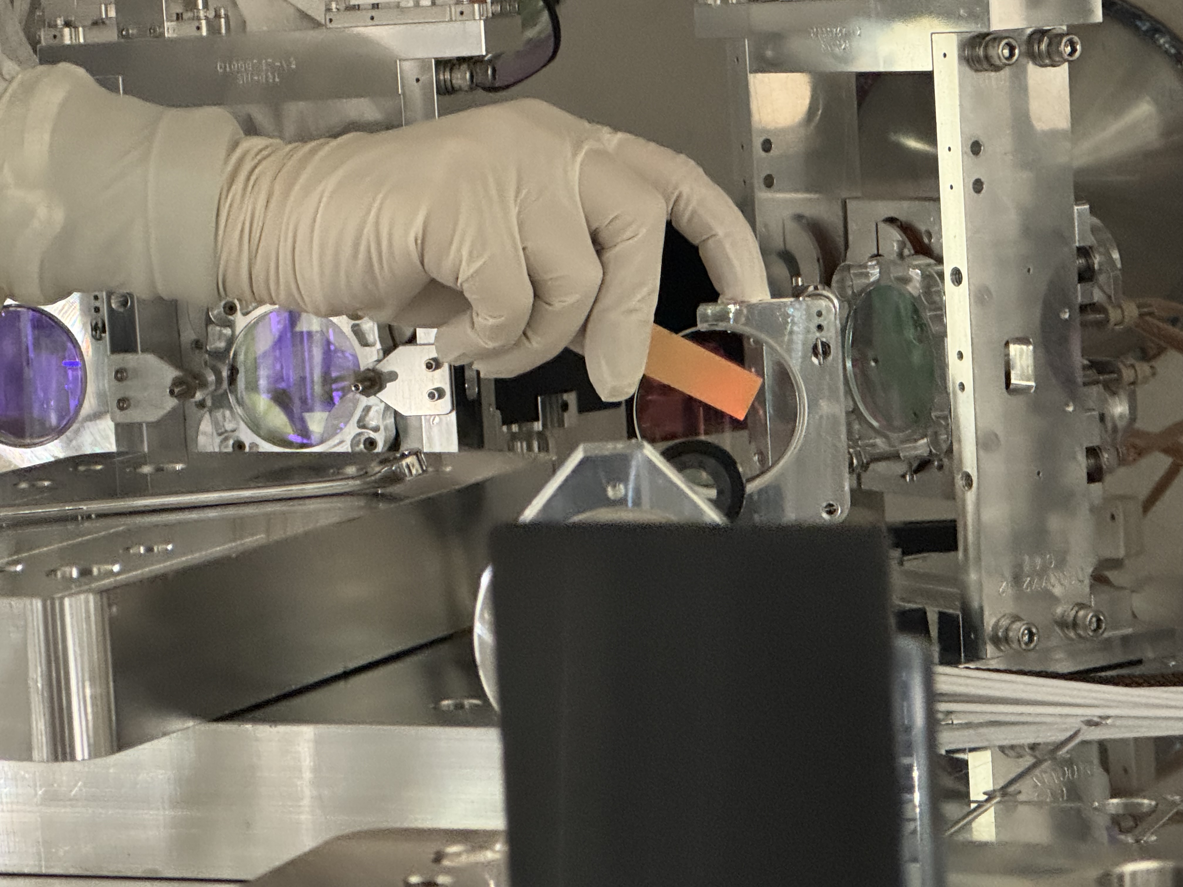
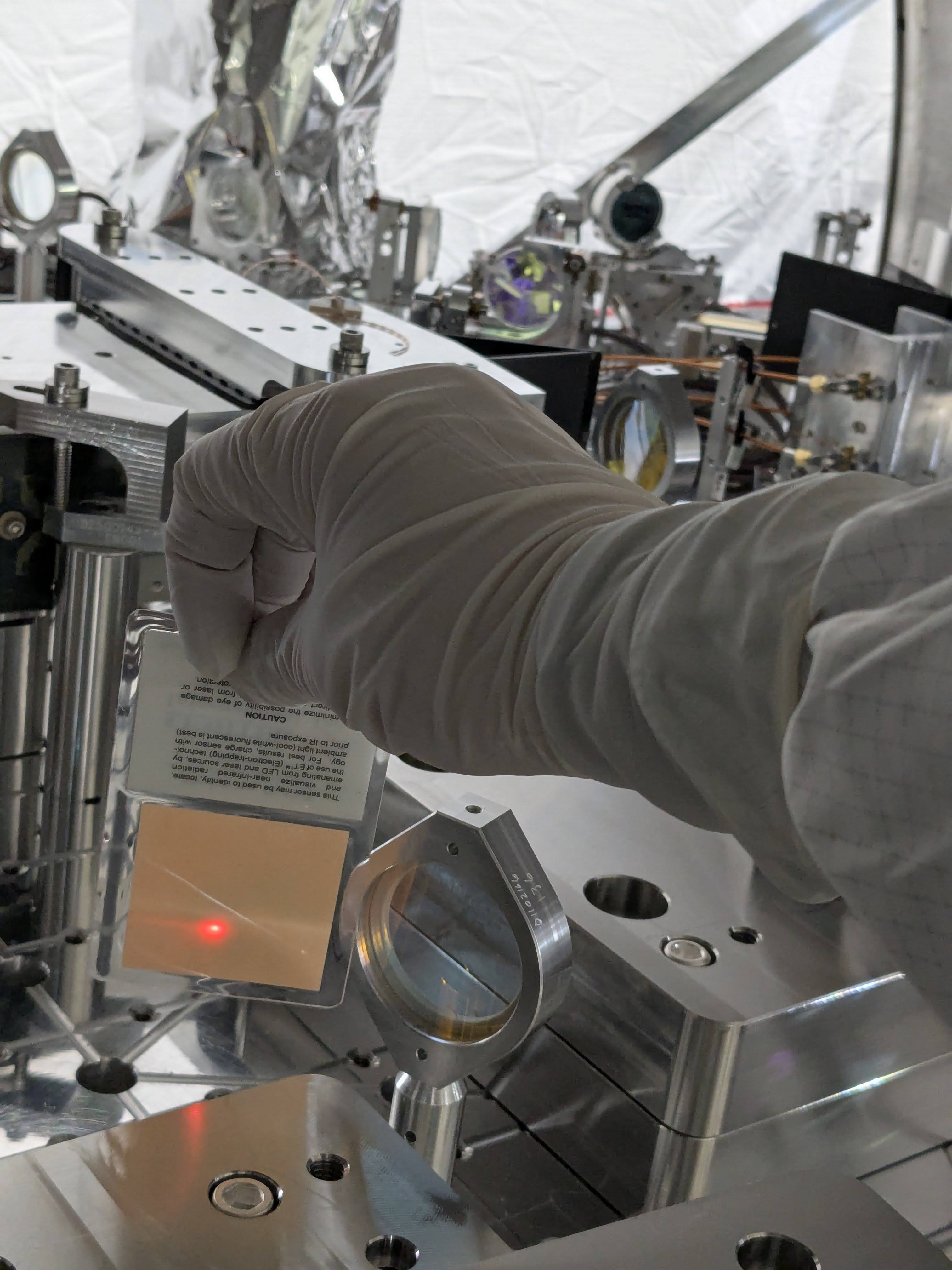
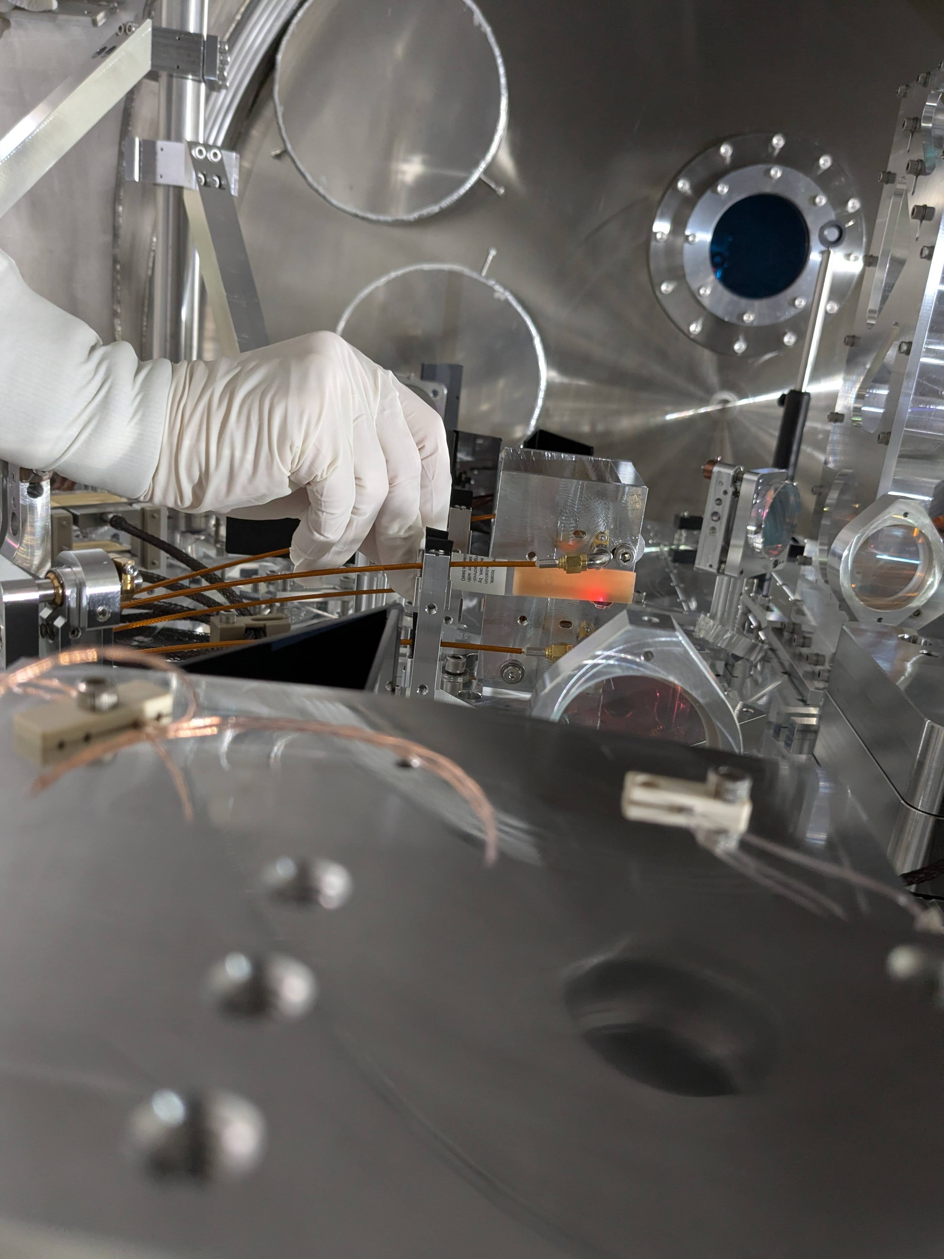
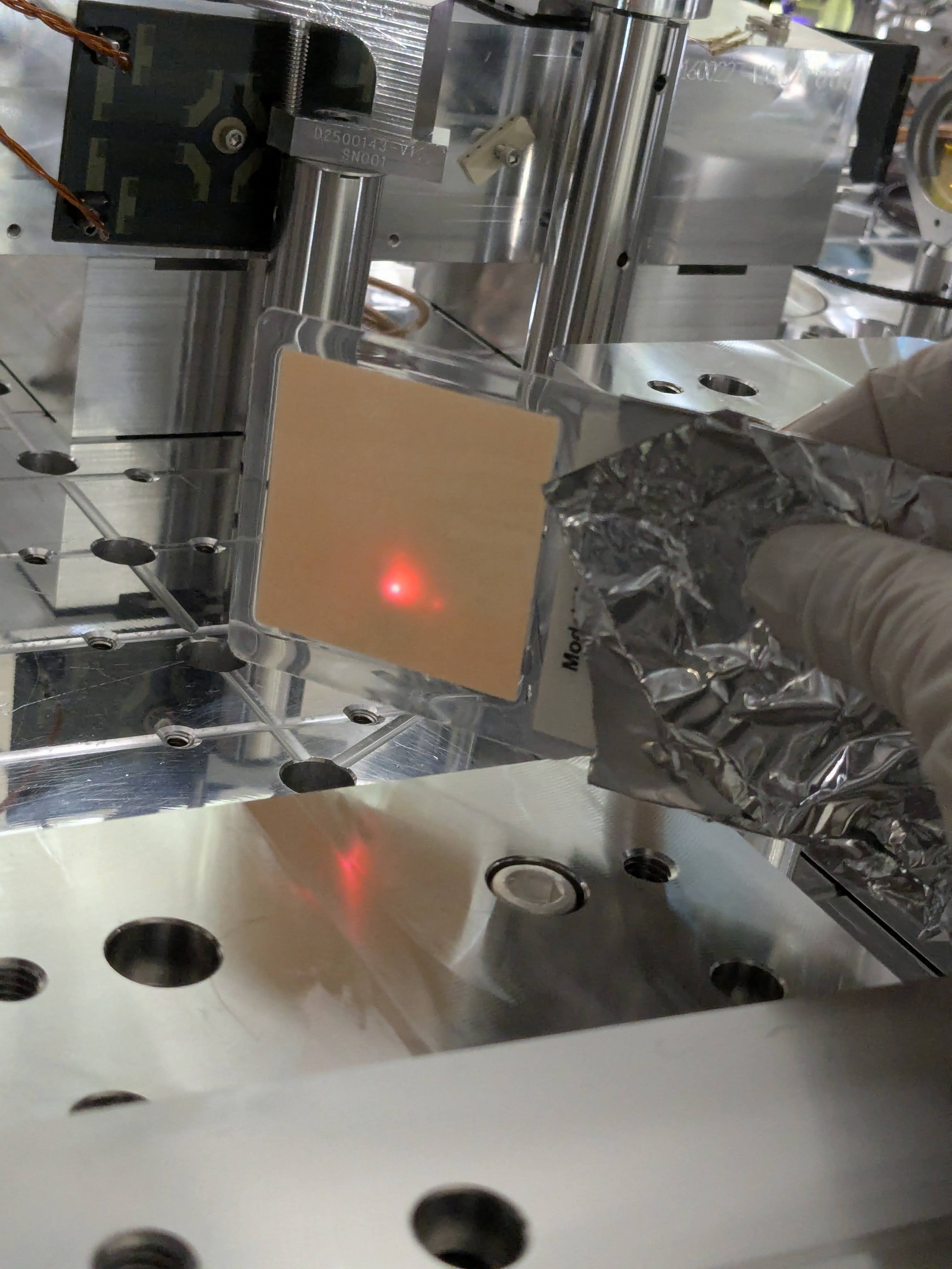
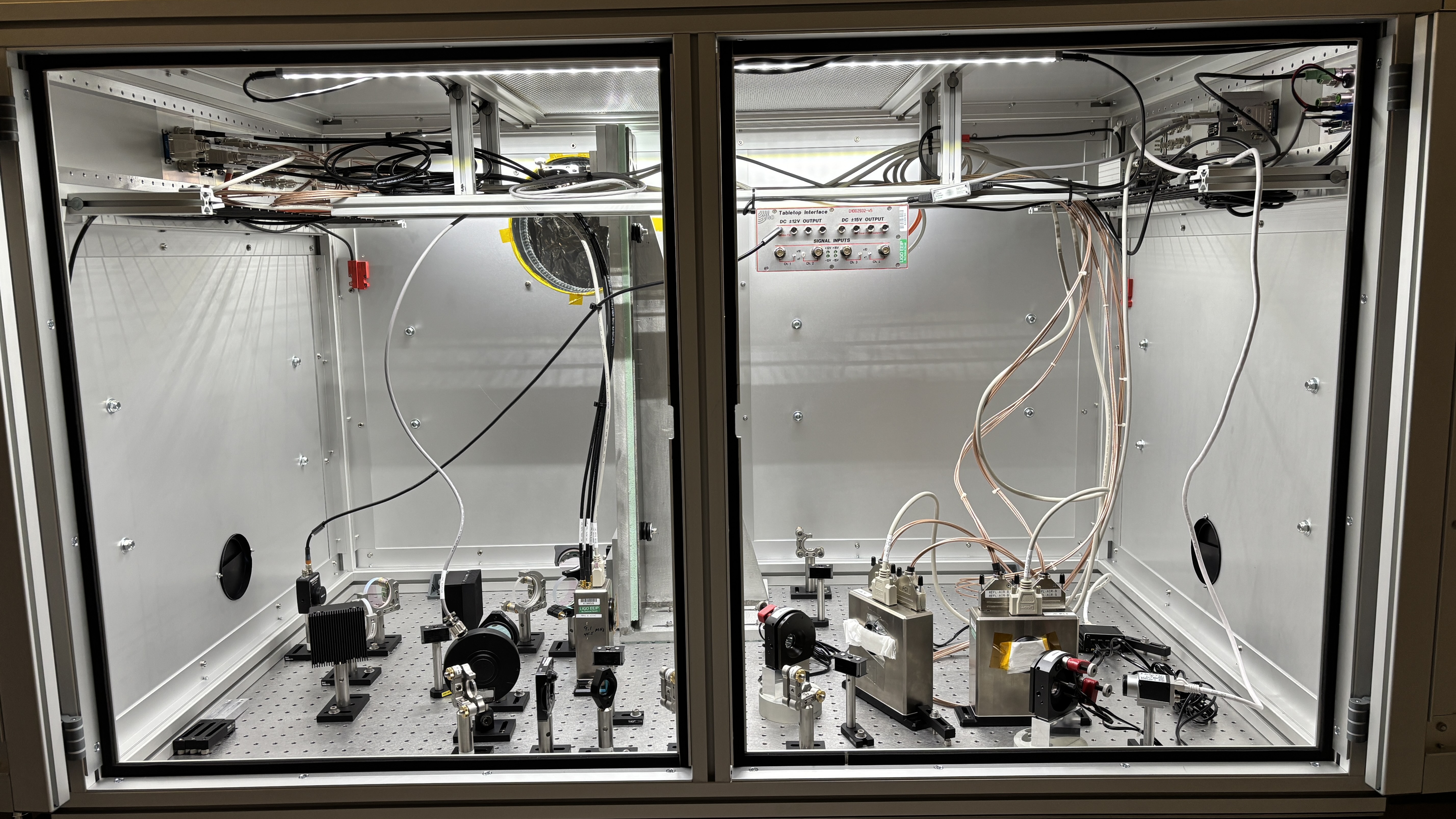
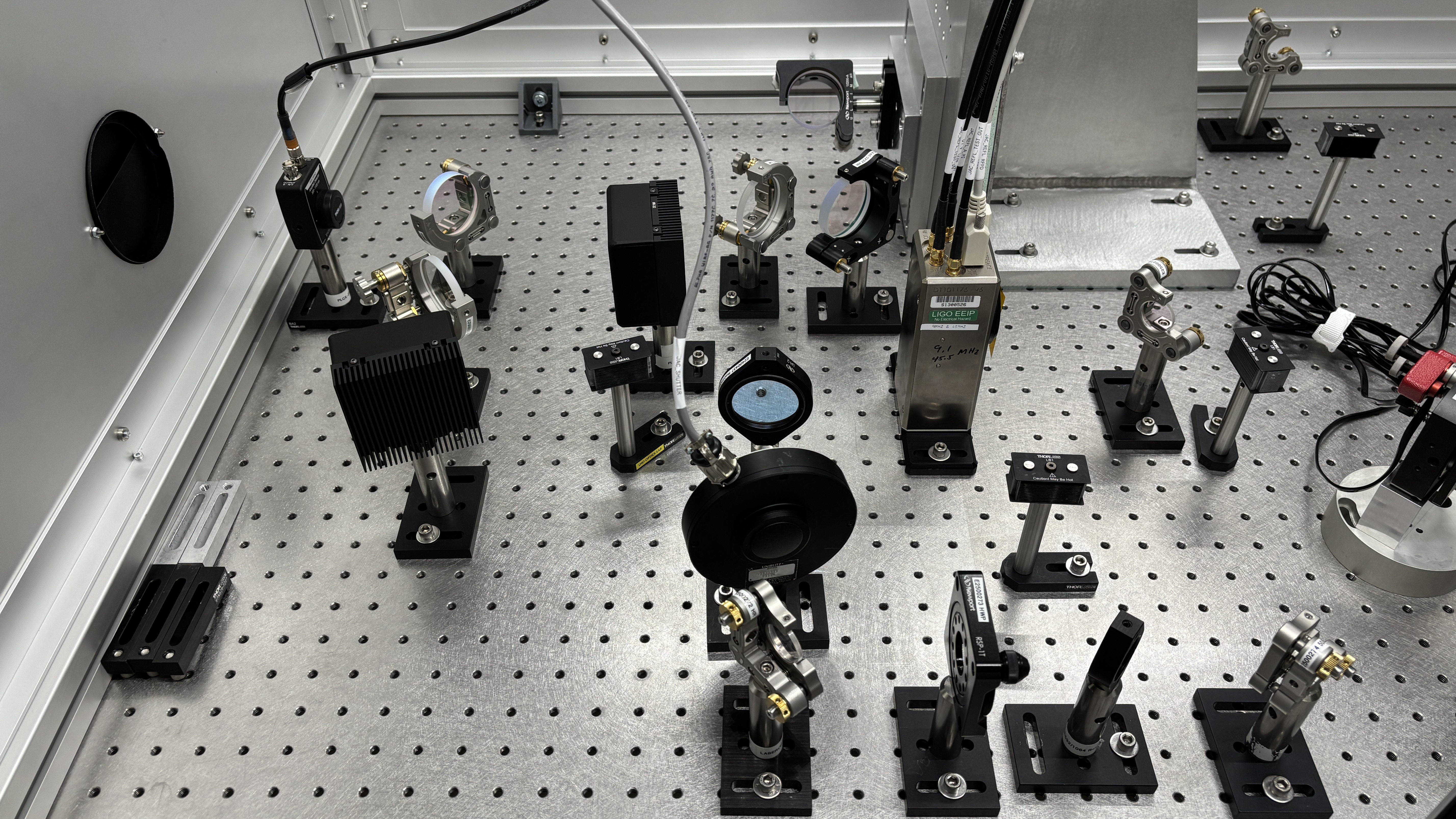
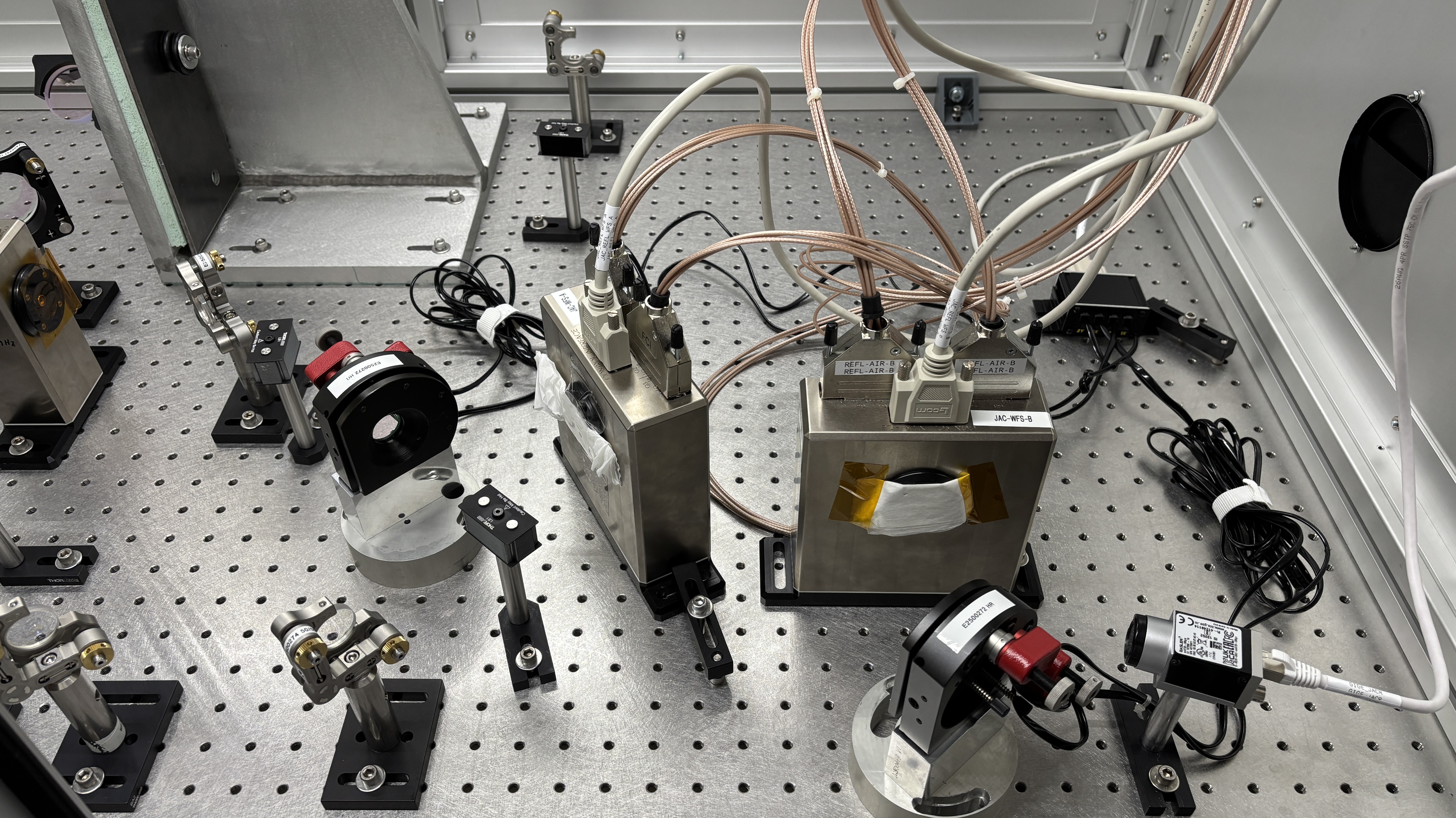
(0') Due to initial confusion of the wavelength of the AxcelPhotonics butterfly diode laser, we also set up an independent OzOptics DTS0081 fiber coupled laser as well, both per LHO Optics Lab SOP (M1800318). See attached picture of setup that allowed for easy interchange between the two seed lasers. We confirmed that they're both \lambda = 1064 [nm].
(3') After the lens was secure and we confirmed that the beam diameter remained at 4073 [um], we wanted to check that disconnecting and reconnecting the fiber from/to the collimator wouldn't impact the lens position. As such, after the initial measurement [Trial 1], we disconnected / reconnected / remeasured three more times with the AxcelPhotonics laser, and once with the OzOptics laser, confirming that the beam diameter stayed at
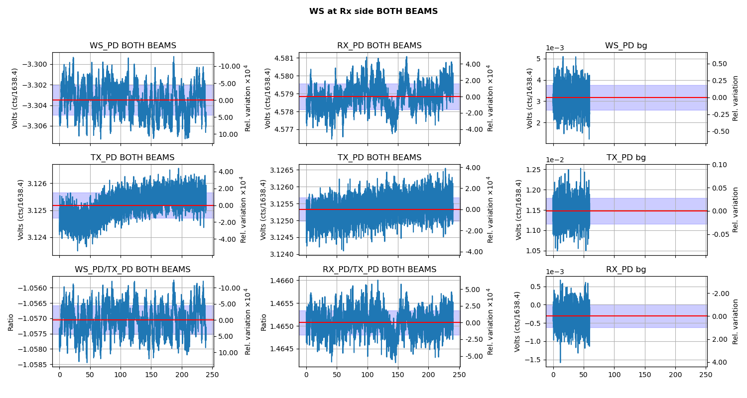
DX (z = 5.41[m]) = 4079.6 +/- (17.3, 7.2)
DY (z = 5.41[m]) = 4084.2 +/- (8.3, 3.7)
with the parentheticals being the standard deviation of the 5 values (matlab's std(vals)), and the standard error on the mean (std(vals) / sqrt(N=5)).
Confident that the lens position is where we wanted it to be, assuming w0 = 1.05e-3 and \lambda = 1064 [nm], we scanned the beam along the z position with both lasers. The raw scan data can be found in the attached OzOpticsLaser and AxcelPhotonics.txt files, in the JaMMT-friendly format of
Scan Position X beam *radius*, Y beam *radius*,
z, [cm] wX(z) [um] wX(z) [um]
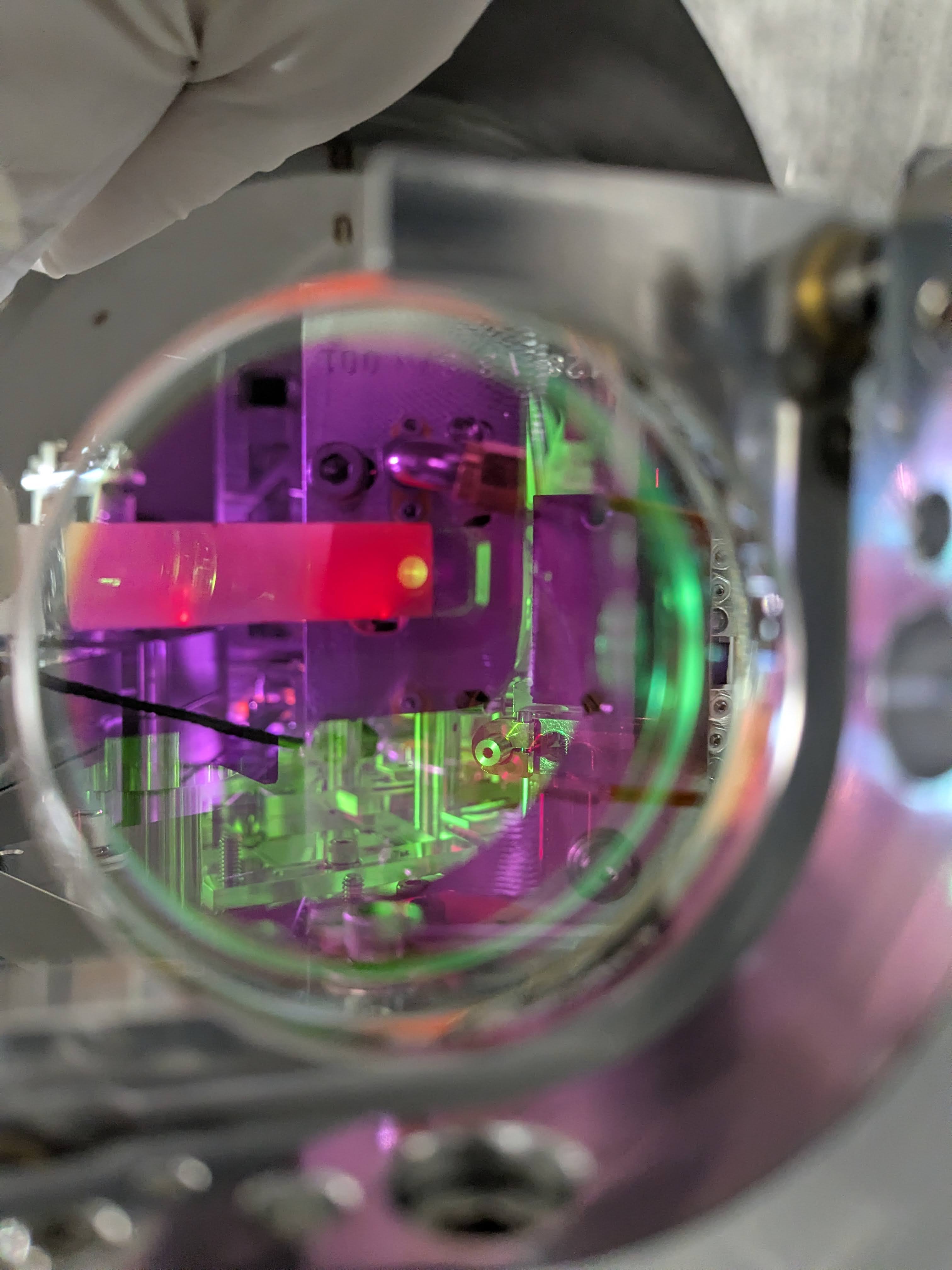
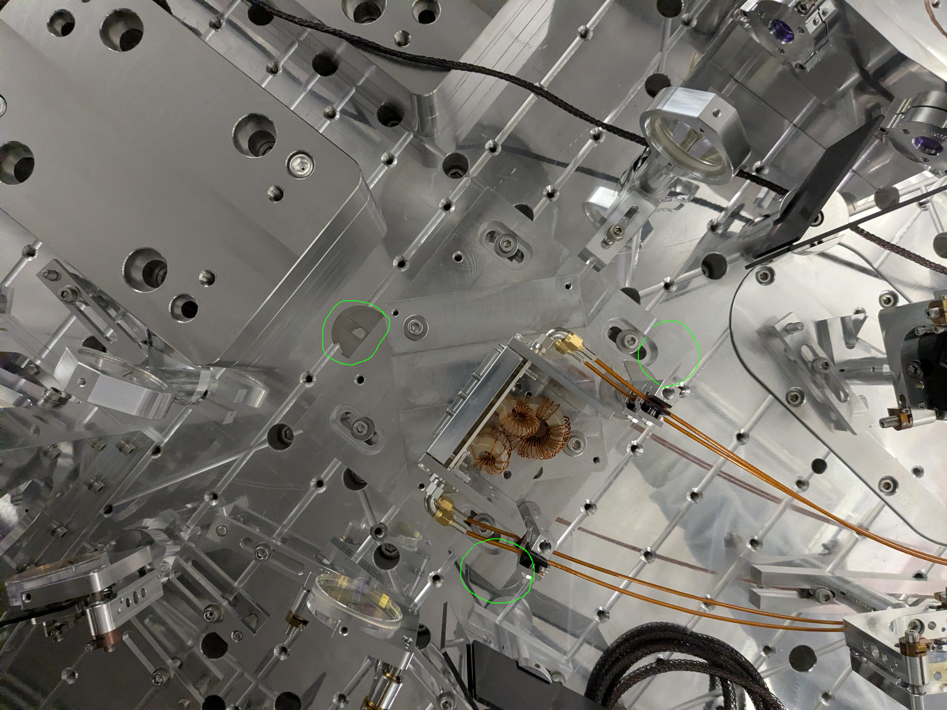
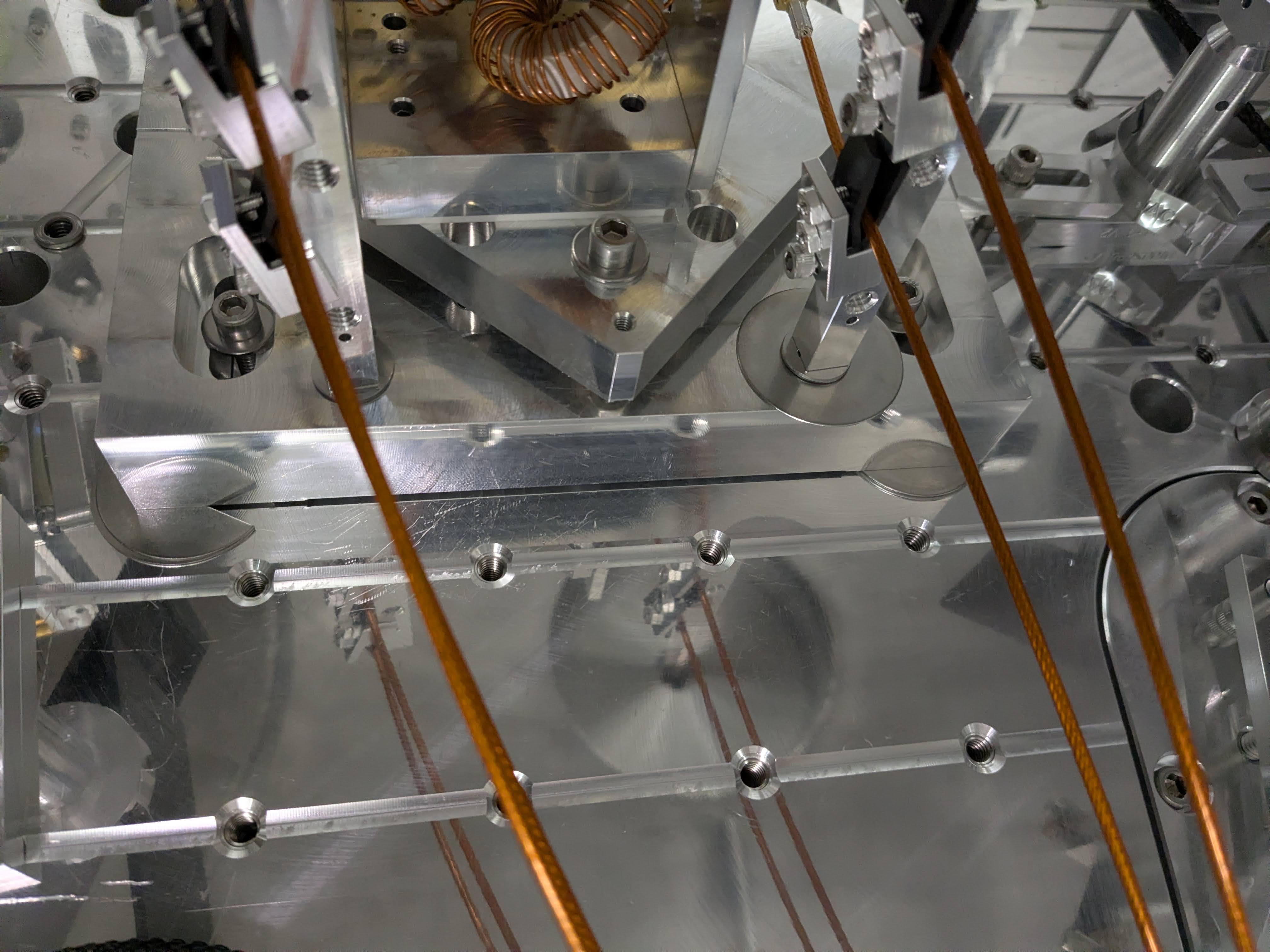
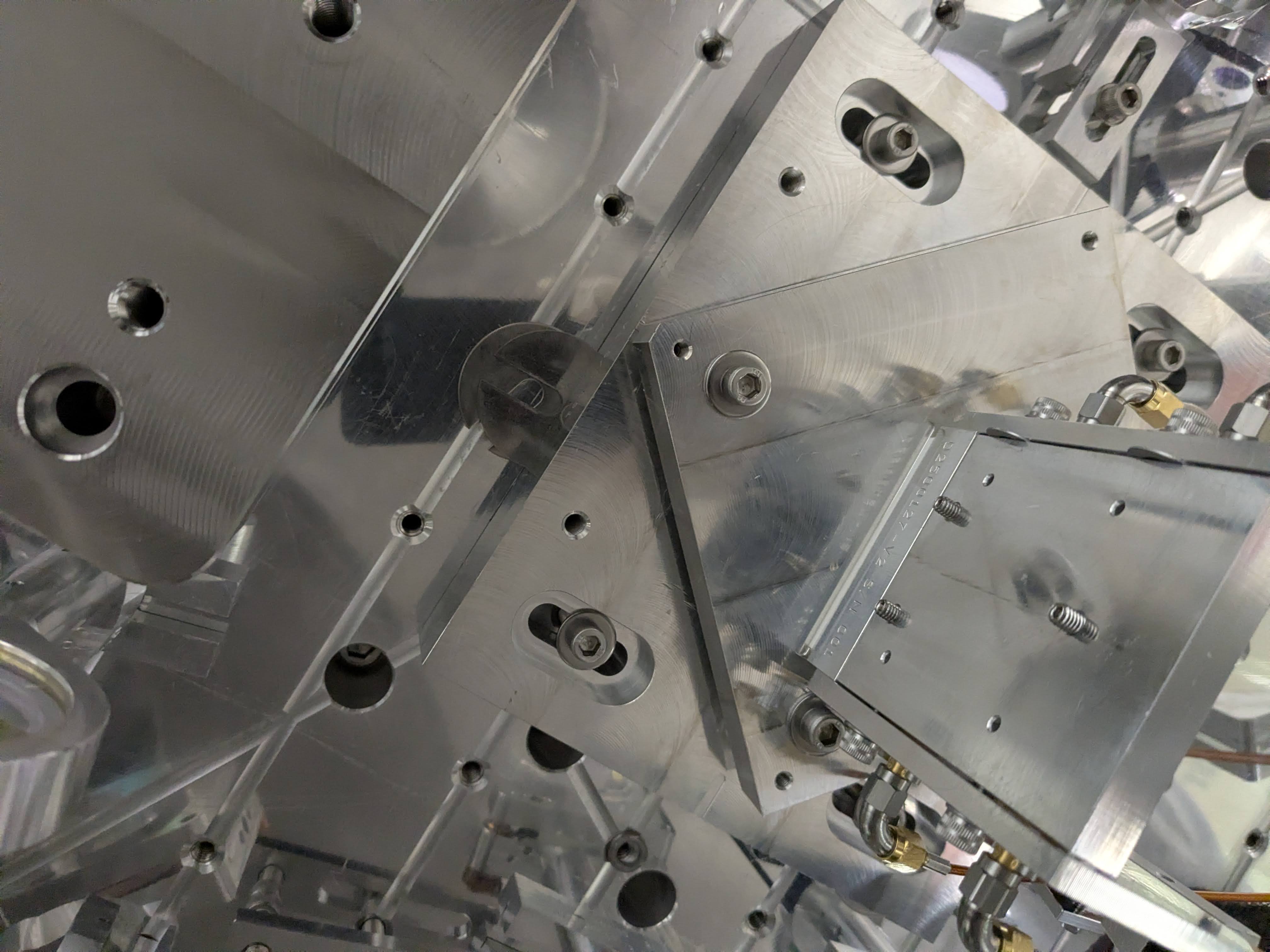
Photos of raw data can be found in this album for the AxcelPhotonics measurement set, and that album for the OzOptics measurement set.
I then pushed that beam profile thru an updated version of my 2025 matlab code (which uses a la mode at its core; attached here for posterity) to fit the profile for waist radius, w0 and waist position, z0.
The fit predicts a waist w0 of
(w0x, w0y)_OzOptics = (0.7040, 0.6766) [mm]
(w0x, w0y)_AxcelPhotonics = (0.6807, 0.7049) [mm]
at position
(z0x, z0y)_OzOptics = (1.4940, 1.5837) [m]
(z0x, z0y)_AxcelPhotonics = (1.5803, 1.4869) [m]
See attached plot.
The good news is that the beam is of excellent Gaussian property (quite symmetric in X and Y), and the fit results of the profile measurements with two independent seed lasers agree.
However -- even after fixing the method mistake of reading off the D4sigma as radii vs. diameter as was the case in the 2025-06-03 and 2025-08-07 measurement sets/fits -- there's a systematic error in this method :: setting the beam diameter to D(z=5.41 [m]) = 4073 [um] consistently puts the z position of the waist, z0 continuously ends up at ~1.5 [m], rather than at 0.0 [m] where we want it.
Having brought up this issue with our wise laser mage (Sina), she isn't surprised and helped guide us toward the source of systematic error: the statement in Figure 3 of Section 1 of the ISIK Assembly Procedure T2400413 about the waist of the beam being w0 = 1.05e-3 [m]. This is *an* ideal case, in which the parameters of the PM980 fiber as spec'd:
- a core radius of 2.75 [um],
- a "nominal" numerical aperture of 0.12 [ ]
- a the seed \lambda = 1064 [nm],
that (using this MFD calculator) yields a "mode field diameter" MFD = 7.14 [um].
Setting the mode field diameter as the beam diameter, at lens D(1/e^2) = 7.14 [um] in the core, butt up against the f=11 [mm] focal length lens in the collimator, and that (using this Laser Spot Size Calculator, and an ideal M^2 = 1.0 [ ] beam quality) yields a "beam diameter at focus" -- the waist diameter, D0 = 2.09 [mm], or w0 = 1.045e-3 [m] ~ 1.05e-3 [m].
This answer to the calculation for w0 was originally pulled from the SPI conceptual design Slide 60 of G2301177, before we even settled on the particular parameters of the 60FC line of SuK collimators, hence the "nominal" value for numerical aperature.
In fact, the technical data for the 60FC-0-A11-03-Ti SuK collimator we're using says the numerical aperture is NA = 0.25 [ ]. That puts
- MFD = 4.67 [um],
- the waist diameter at D0 = 3.19 [mm],
- waist radius at w0 = 1.595 [mm],
- Rayleigh Range at zR = 7.5 [m],
- Diameter D(z=5.41 [m]) = 3931.3 [um]
... quite different.
In fact, if that is the case, and the Rayleigh Range is 7.5 [m] instead of 3.25 [m], then I need to extend our range of measurement positions well beyond 5.41 [m]...
But in short -- the core radius and *actual* numerical aperture may be different than even this specific FC model, and the focal length of the lens might not be exactly 11.00 [mm].
As such, we need to
- use this measured beam profile to backward propagate through the lens and *fit* for the MFD (convert it beam radius MFw) within the fiber (constant as a function of z along the fiber), rendering he need for a spec'd numerical aperture and core radius value moot.
- use the *fit* MFw to then forward propagate out (again) through fiber collimator lens, and determine the waist radius, w0, of the out-going free-space beam.
- from there, recalculate the Rayleigh Range and thus target Beam Diameter at each measurement position.
Back to the drawing board!


