[Camilla, Jenne]
Some belated notes about trying LSC FF back on Sept 21st, as well as notes on measurements taken today for retuning the LSC FF using ETMY PUM.
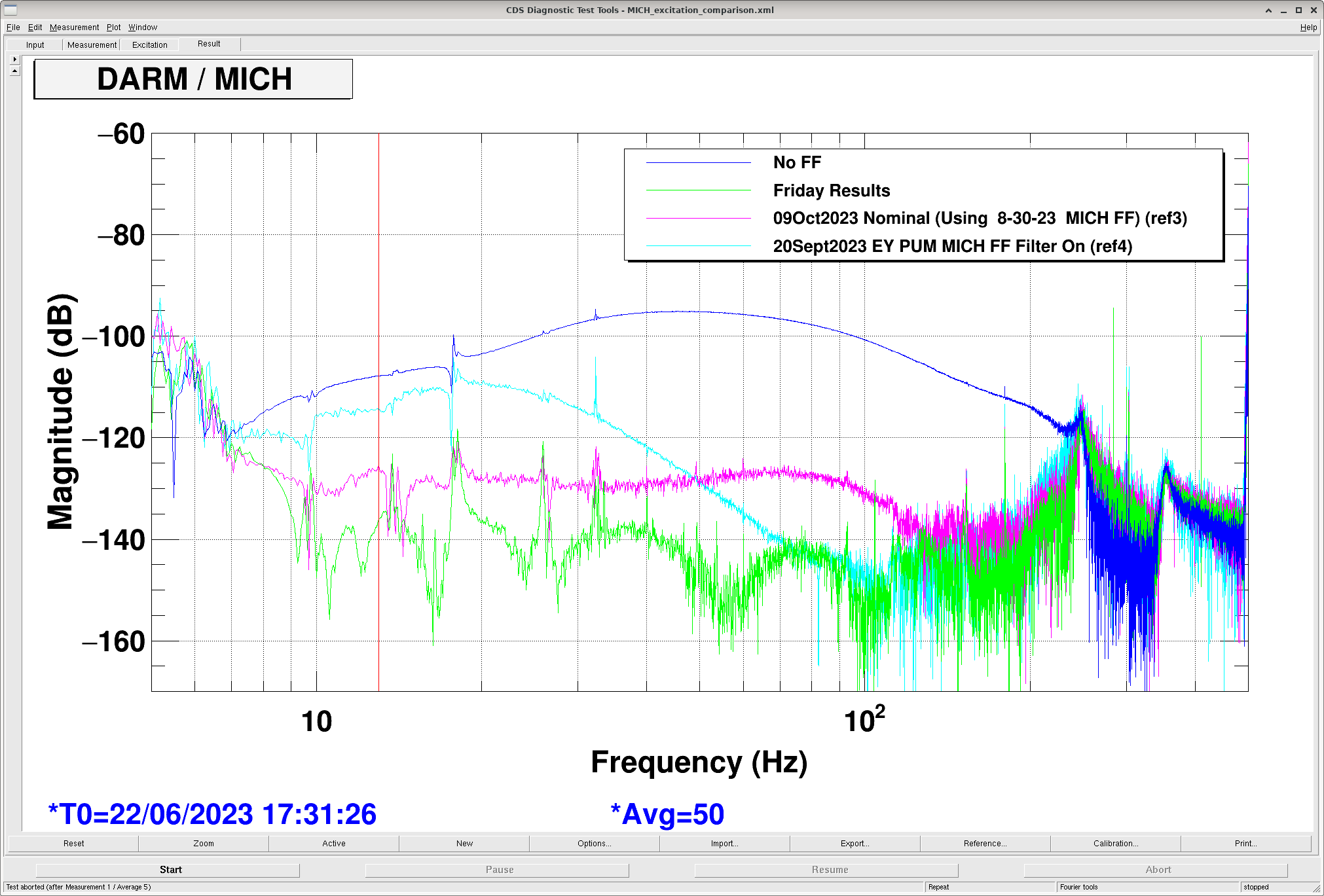
LSC FF with ITM PUM did not work when I tried it on 21Sept2023 (turning on MICH FF worked okay, but turning on SRCL FF killed the lock. We have seen this before in years past at LHO that we cannot use SRCL FF with the ITMs, likely due to a parasitic loop). The measurements and fits for that were in alog 72862.
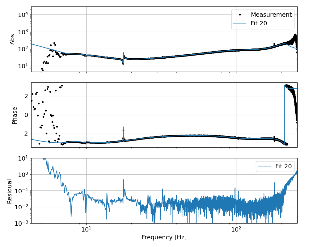
Measurement for MICH FF using ETMY PUM taken 20 Sept 2023 (I forgot to alog). Lost lock trying to gather SRCL FF data at that time. Gabriele fit the MICH FF data and gave us a filter (below, and attached).
Camilla and I tried that filter from September:
- Plotted the filter in Foton, removed a pole/zero pair around 63 Hz with Q of 286 that was unneccessary. Removing this pair made almost no difference to the mag or phase.
- Checked step response, it's very similar to the currently-in-use filters (step is done in 5-6 seconds).
- Prepared for sending LSC FF to ETMY PUM (and not to ETMX test mass) - these are the things we'll need to do in Lownoise_length_control, if we're going to use these filters:
- LSC FFs both ramped off
- LSC FF matrix off the EX, leave on the EYs at -1.
- LSC main darm outmtrx zeros to EY
- Make sure EY on with gain of 1 through ISCINF, L3 LOCK, L2 LOCK. L2 lock has on Qprime filter, which is a f^2.
- Turned on MICH FF using Sept 21st filter.
- Sept 21st filter didn't work well. Just going to turn it off, and measure both MICH and SRCL from scratch.
Measuring MICH and SRCL FF, while still using EY PUM:
- With LSCFF still set to actuate on EY PUM, measured MICHFF exc with only the highpass on.
- Then turned back on *old ETMX* FF and measured MICH excitation (FF only on to give better SNR with DARM, so shouldn't matter which FF).
- Measured SRCL excitation
- Switched off LSCFF, re-set-up actuation to ETMY PUM, then measured SRCLFF excitation with only it's two highpass filters on. This measurement, in the past, caused a lockloss, so we took a little time to tune the excitation to give okay coherence up to ~500 Hz, while not killing the lock.
- DTT templates are all saved in .../userapps/lsc/h1/scripts/feedforward/ .
- Work on fitting these data is ongoing.
MICH filter using ETMY PUM from 20 Sept 2023, plotted in attachment: zpk([-8.392330076183118+i*49.39248514742469;-8.392330076183118-i*49.39248514742469;-1.046997552323544+i*62.74012764734476;-1.046997552323544-i*62.74012764734476;-0.195079334716182+i*111.0307750783754;-0.195079334716182-i*111.0307750783754;-67.32125480645517+i*108.7955724988948;-67.32125480645517-i*108.7955724988948;-0.7011570088542948+i*401.6350155234317;-0.7011570088542948-i*401.6350155234317;-2.779238087179218+i*518.2808819075473;-2.779238087179218-i*518.2808819075473;-317.3841576035709+i*1079.288485296243;-317.3841576035709-i*1079.288485296243;-178.8519649481057+i*1320.885890800788;-178.8519649481057-i*1320.885890800788;49.42179558079376;-126.1091578653822;-342.6998780810434;-387.3921871872612],[-6.612825148760598+i*18.03485413750199;-6.612825148760598-i*18.03485413750199;-10.51113766874398+i*51.44409984903976;-10.51113766874398-i*51.44409984903976;-1.193259418463134+i*62.71361669508964;-1.193259418463134-i*62.71361669508964;-0.184848231243519+i*111.3871852754391;-0.184848231243519-i*111.3871852754391;-111.7020413312252+i*111.668875814675;-111.7020413312252-i*111.668875814675;-0.7097877123317881+i*401.6301823509122;-0.7097877123317881-i*401.6301823509122;-2.787645529701059+i*518.2913243267907;-2.787645529701059-i*518.2913243267907;-335.0087359797044+i*492.7511937802536;-335.0087359797062-i*492.7511937802536;-227.3099122149132+i*1161.919607907957;-227.3099122149132-i*1161.919607907957;-100.9775239200197+i*1321.691603918431;-100.9775239200197-i*1321.691603918431],-69.94521247458729)