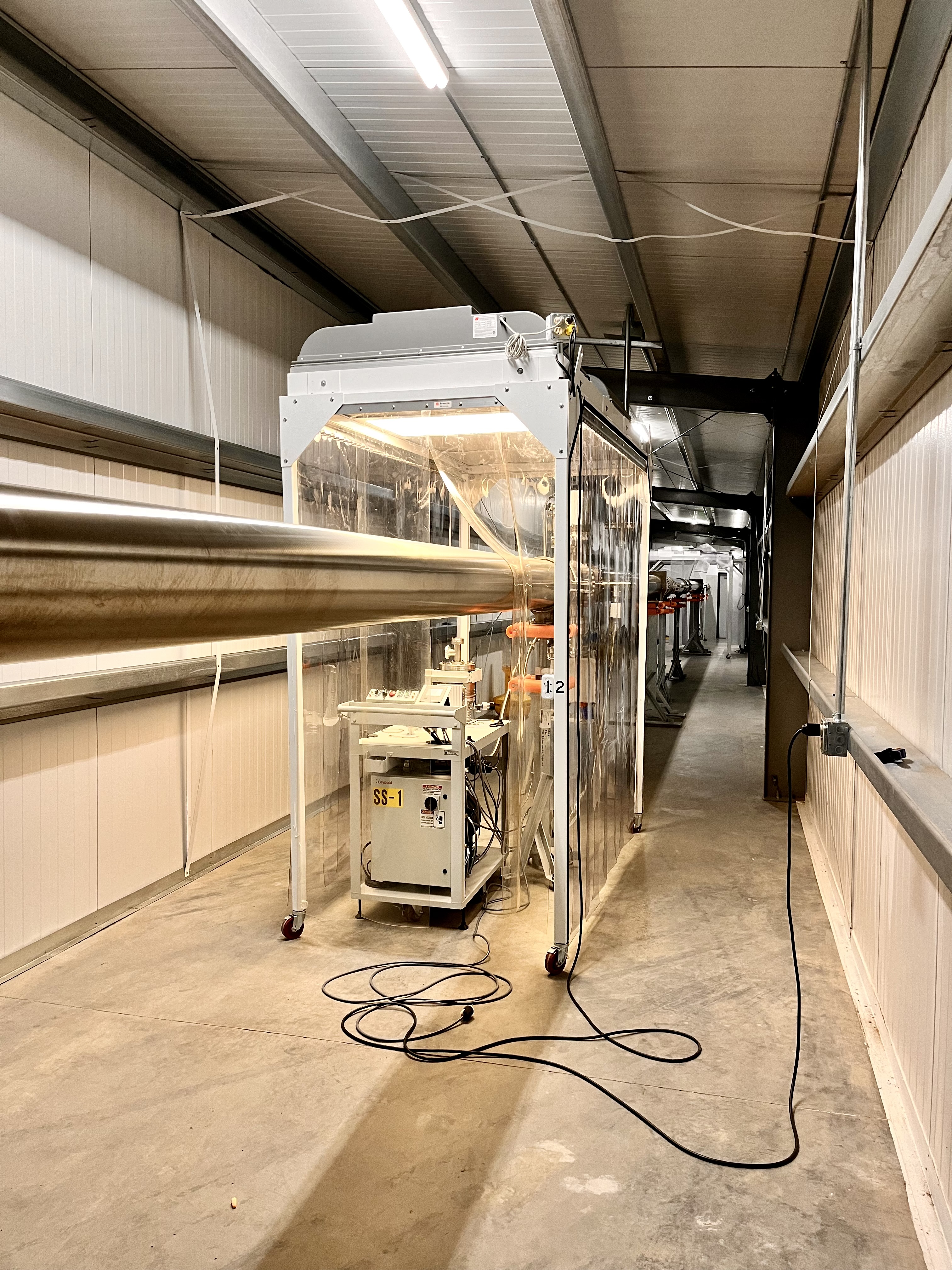
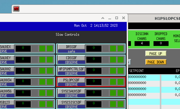
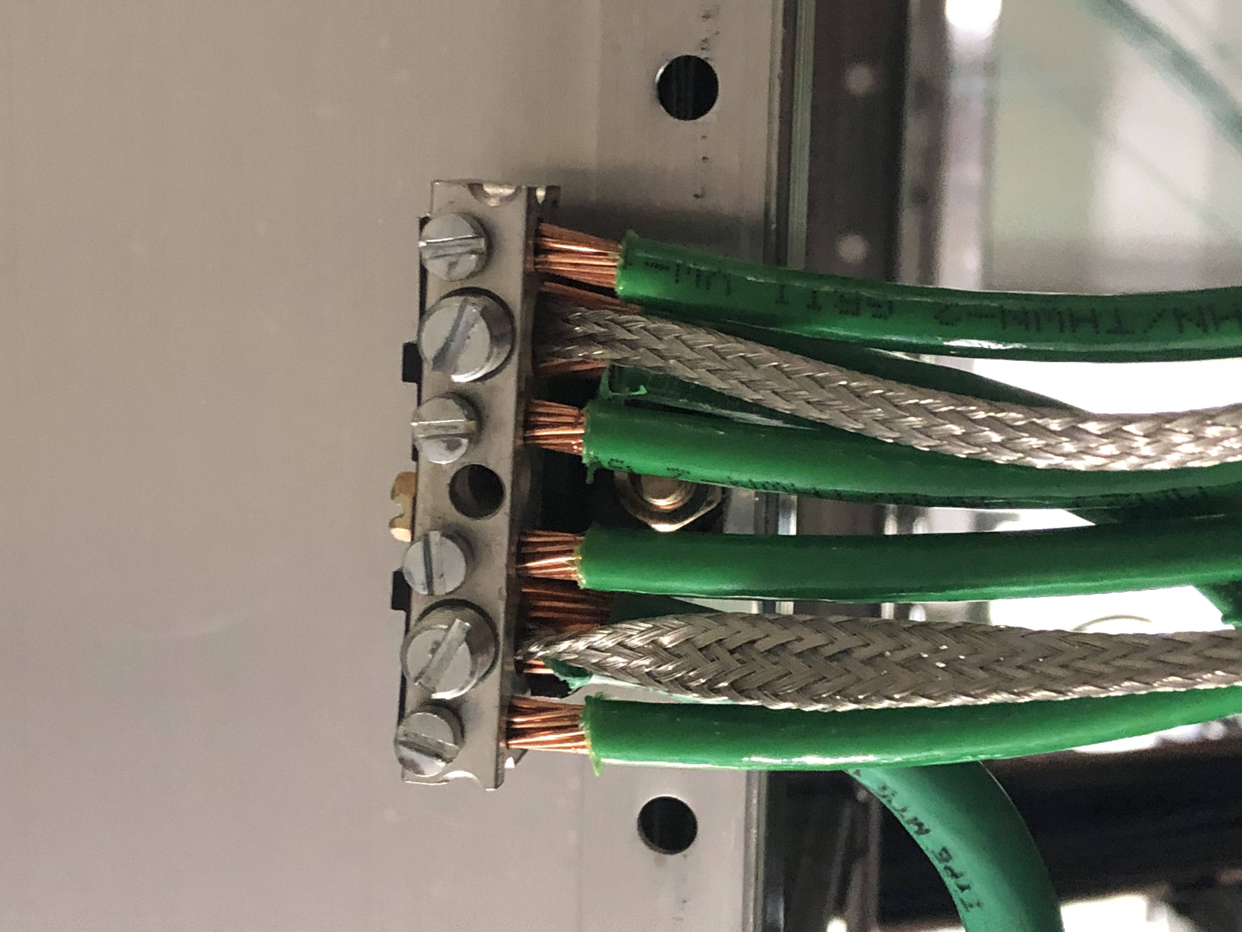
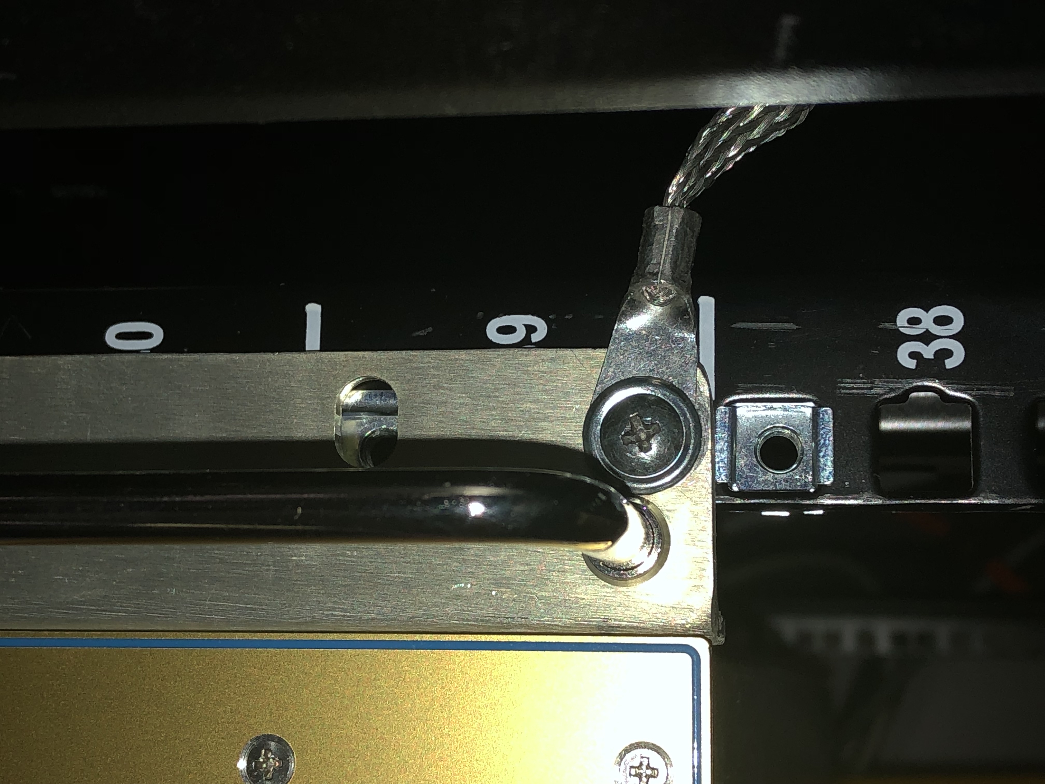
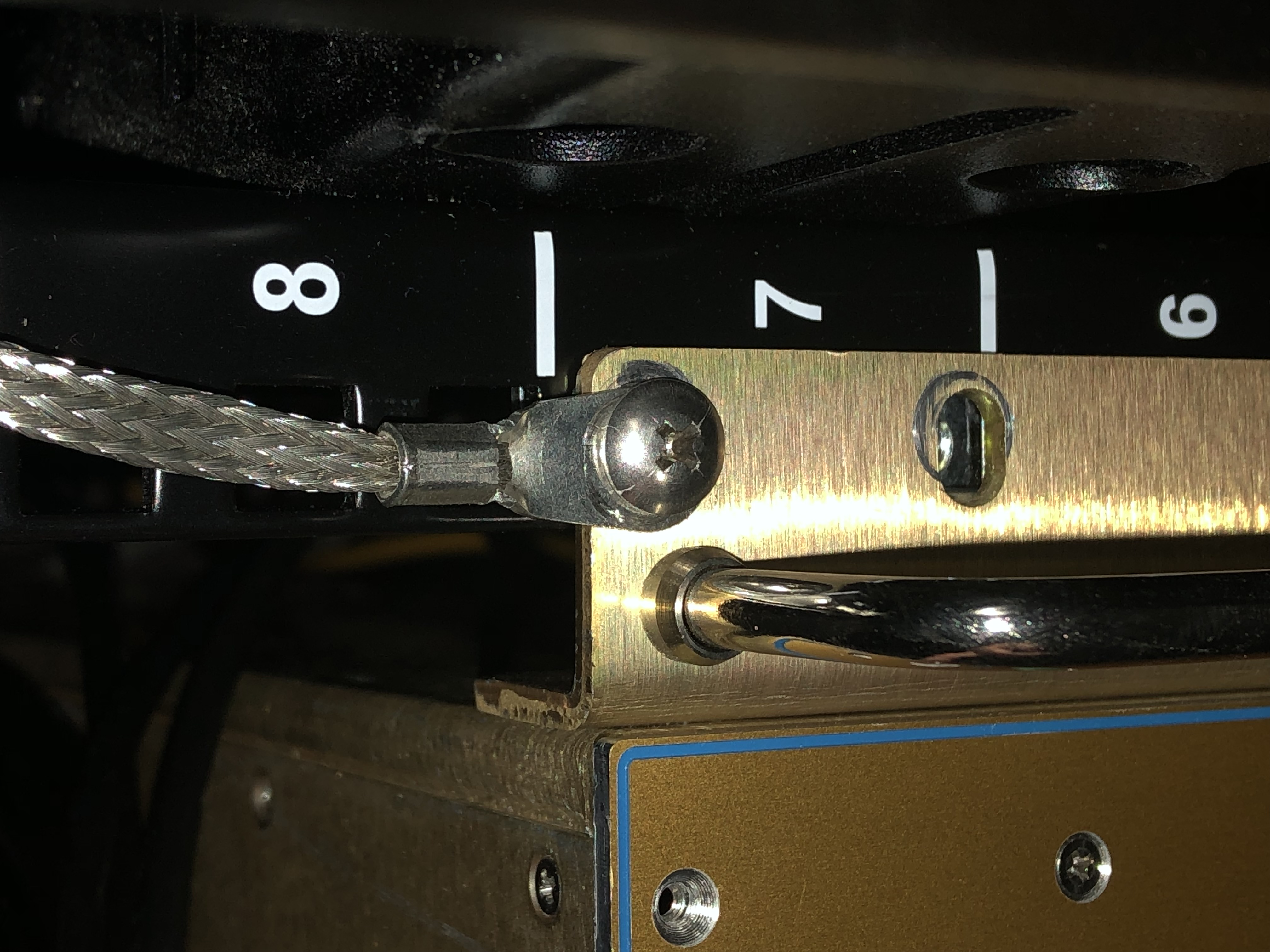
The remaining two slow controls chassis were grounded via a wire braid to a grounding terminal block. Same as what was done in alog 68096, alog 66402 and alog 66469. This scheme provides a low resistance path to the grounding block. The anodized racks prevent a solid grounding connection via the mounting screws. The PSL and TCS slow controls were grounded using new scheme. See attached pictures. This completes all slow controls chassis in CER and End Stations.
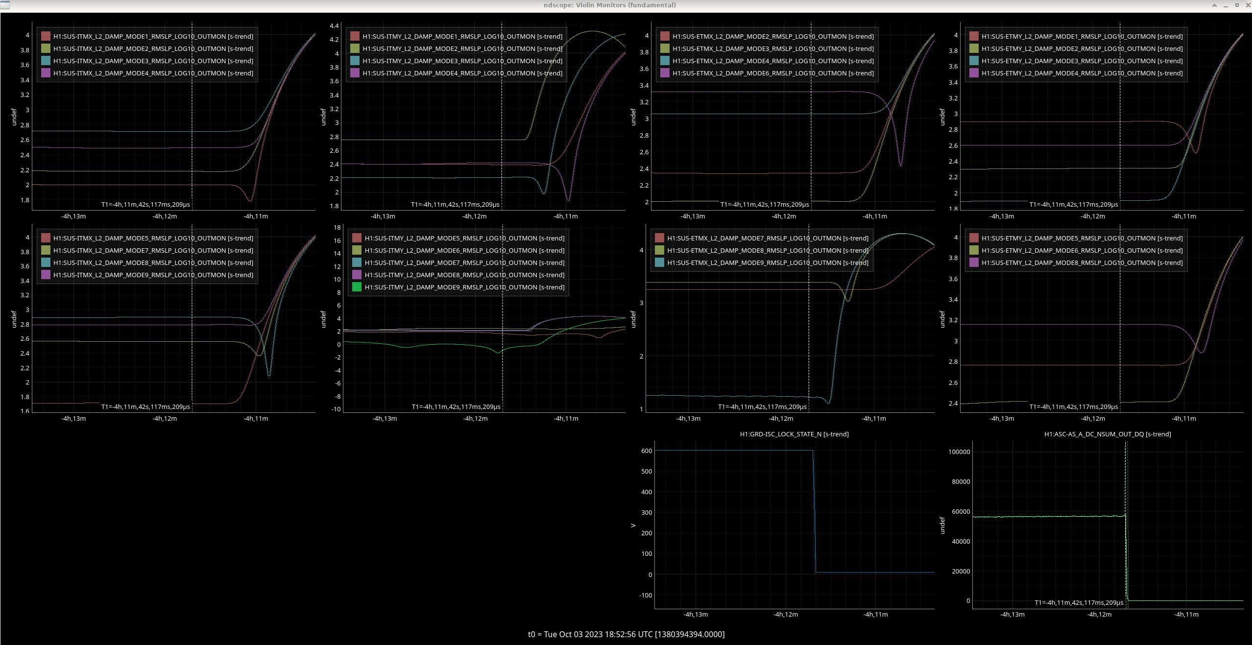
Tagging DetChar -- with the CW group in mind.
After this maintenance day, there might be a change in comb behavior as a result of this work.

This is action taken as a result of Keita, Daniel, and Ansel's work on ID'ing combs from the OM2 heater system -- see LHO:72967.
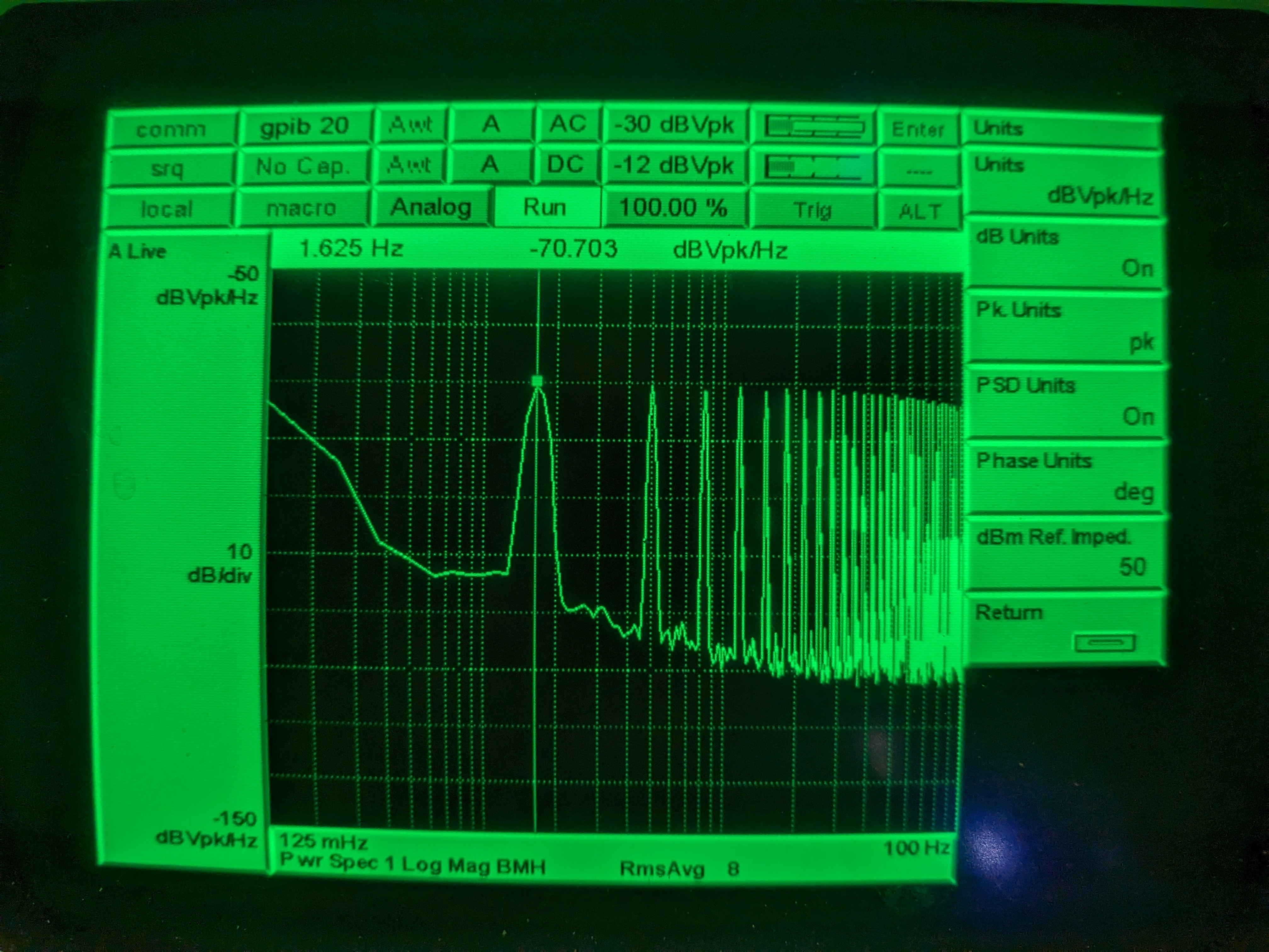
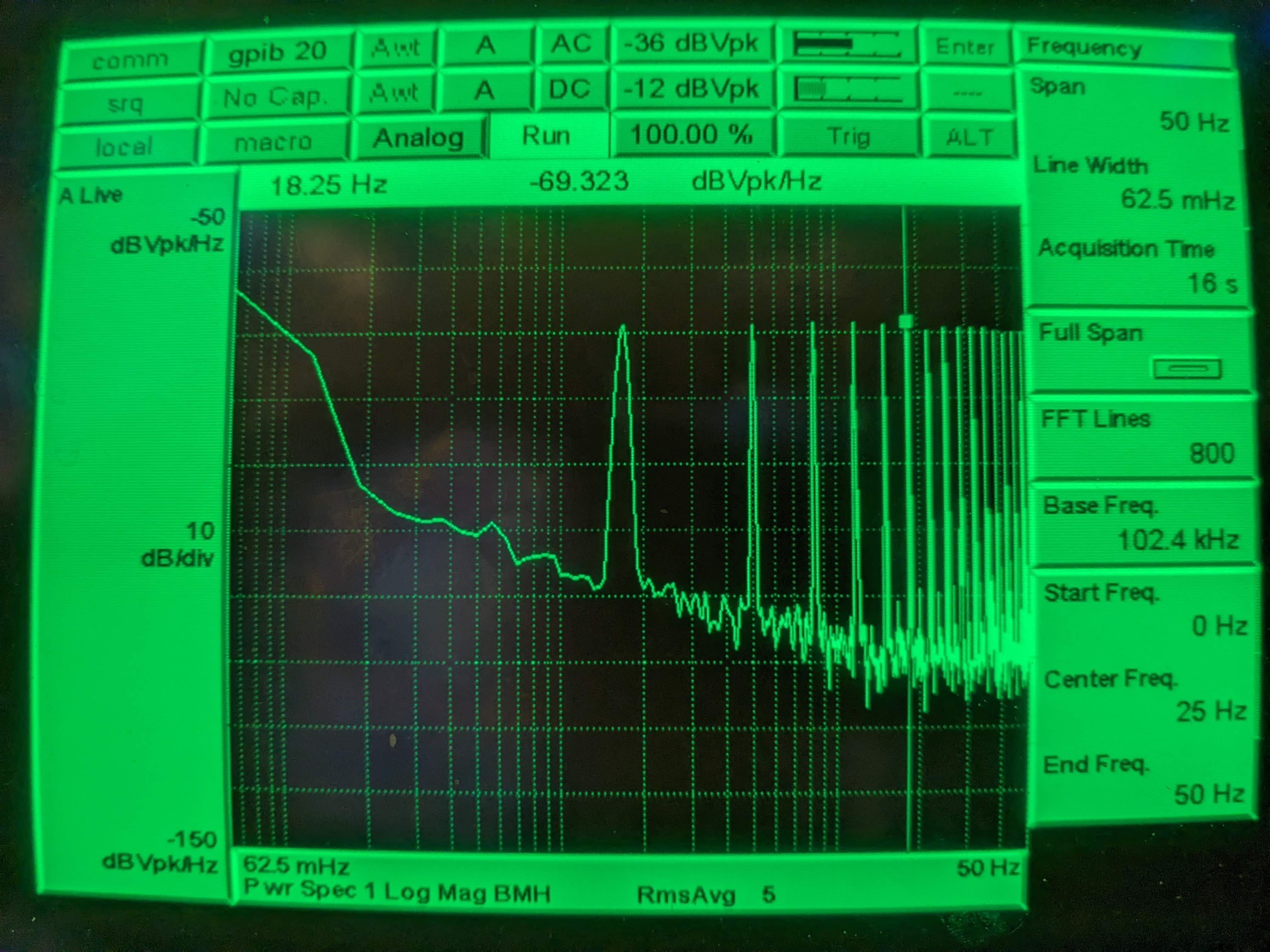
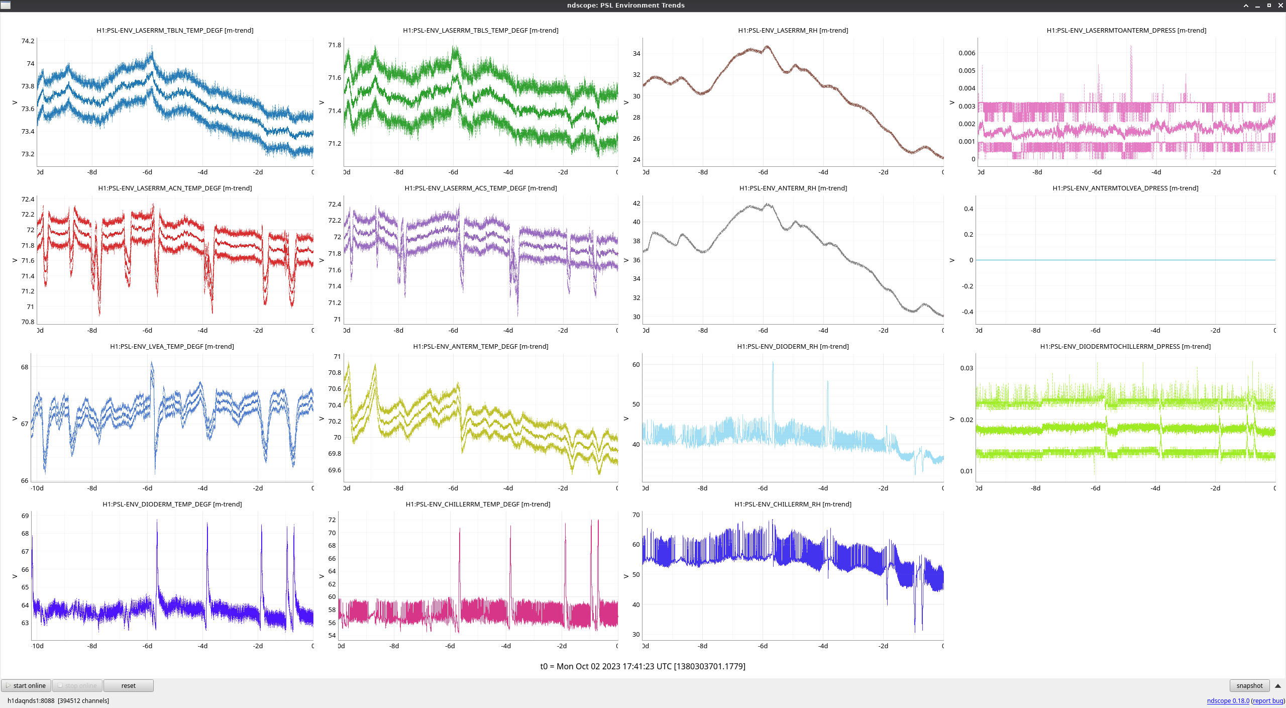
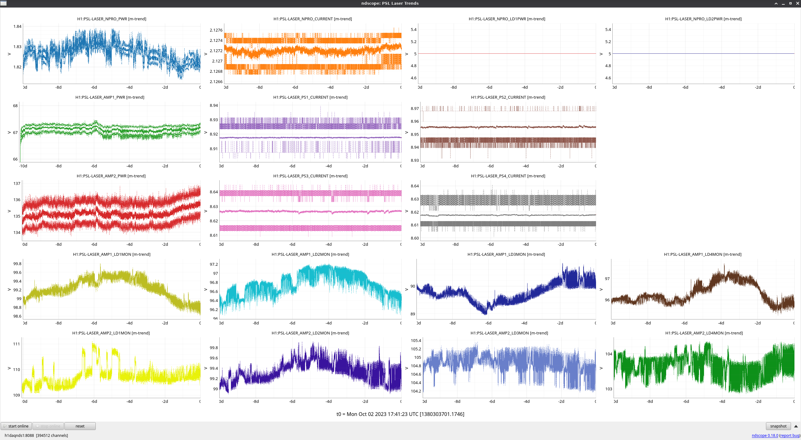
After Fil was done with the grounding work, I temporarily restored the connection between the beckhoff cable and the heater chassis and used a normal breakout board to measure the voltage between the driver ground (pin13) and the positive drive voltage (pin 6) of D2000212, just like I did on Aug 09 2023 (alog 72061).
1st attachment is today, 2nd attachment is on Aug 09. I see no improvement (OK, it's better by ~1dB today).
After seeing this, I swapped the breakout board back to the switchable one I've been using to connect only a subset of pins (e.g. only thermistor 1). This time, there's no electrical connection between any pins but the cable was physically attached to the breakout board. No connection between the cable shell and the chassis connector shell either. I expect that the comb will be gone, but I'd like detchar to have a look.
The heater driver is driven by the voltag reference on the nearby table, not Beckhoff.