TITLE: 09/27 Day Shift: 15:00-23:00 UTC (08:00-16:00 PST), all times posted in UTC
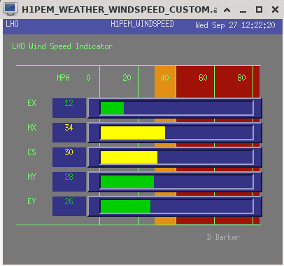
STATE of H1: Wind
INCOMING OPERATOR: Ryan S
SHIFT SUMMARY: Pretty unsuccesful day for locking, we weren't able to relock after the morning LL due to wind.
15:38UTC Superevent S23927be didn't get a verbal alarm for this event, just a phone call.
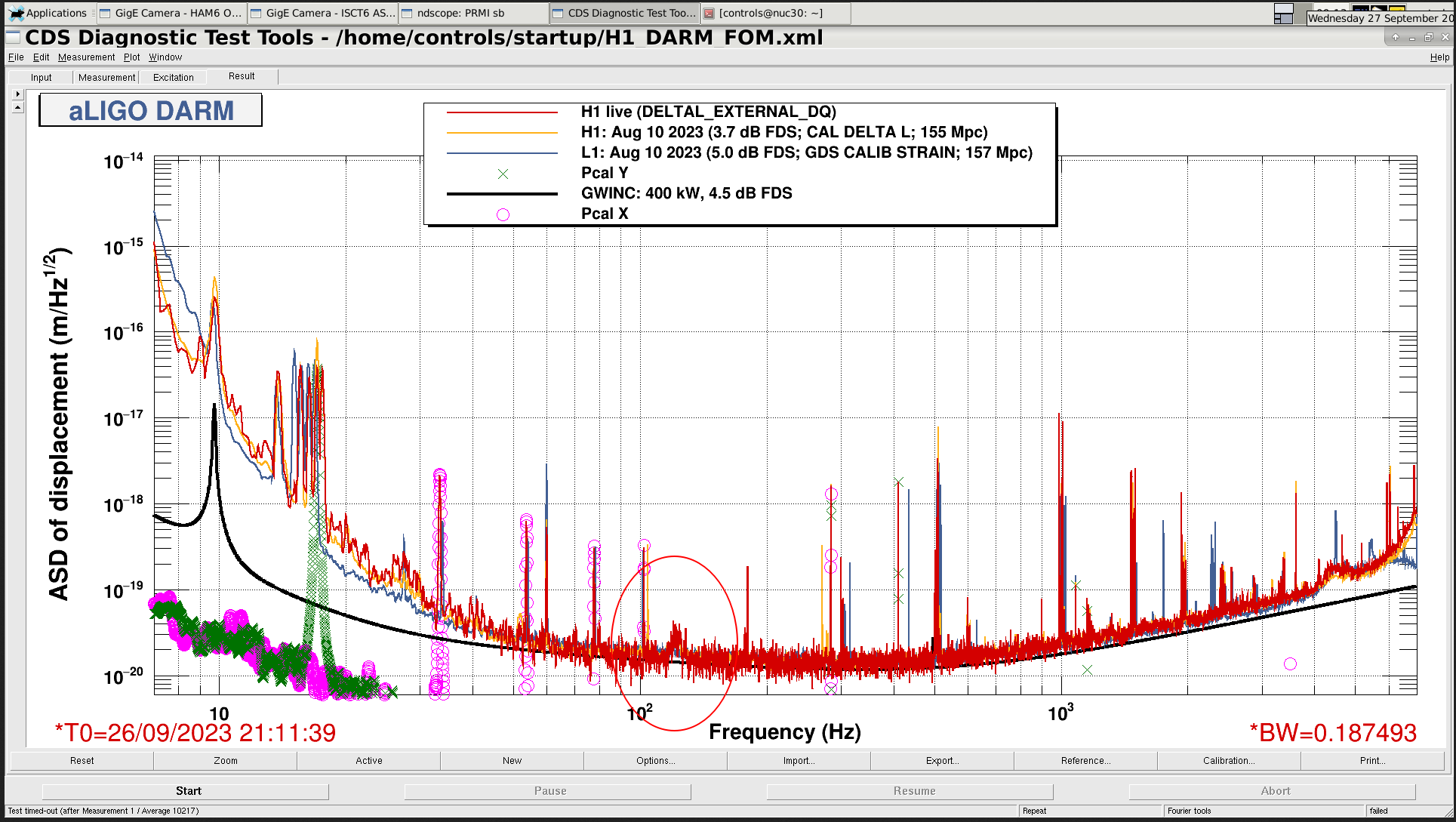
I noticed this bump around 120Hz this week, I'm not sure if this is usually there? (tagging detchar)
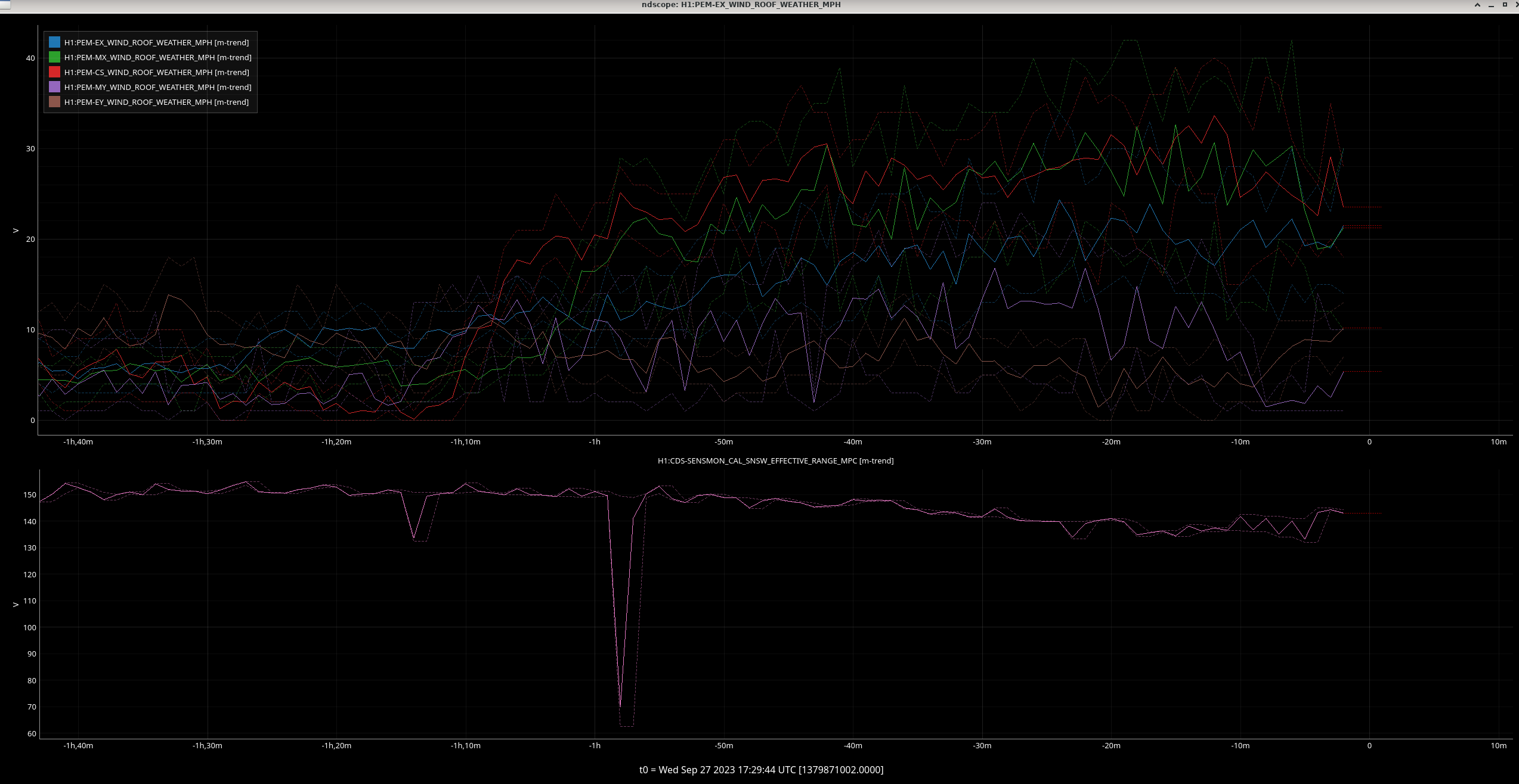
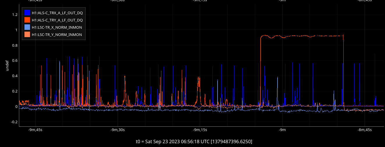
The range started to drop in the morning, it seemed correlated with the winds picking up (gusts up to over 40mph)
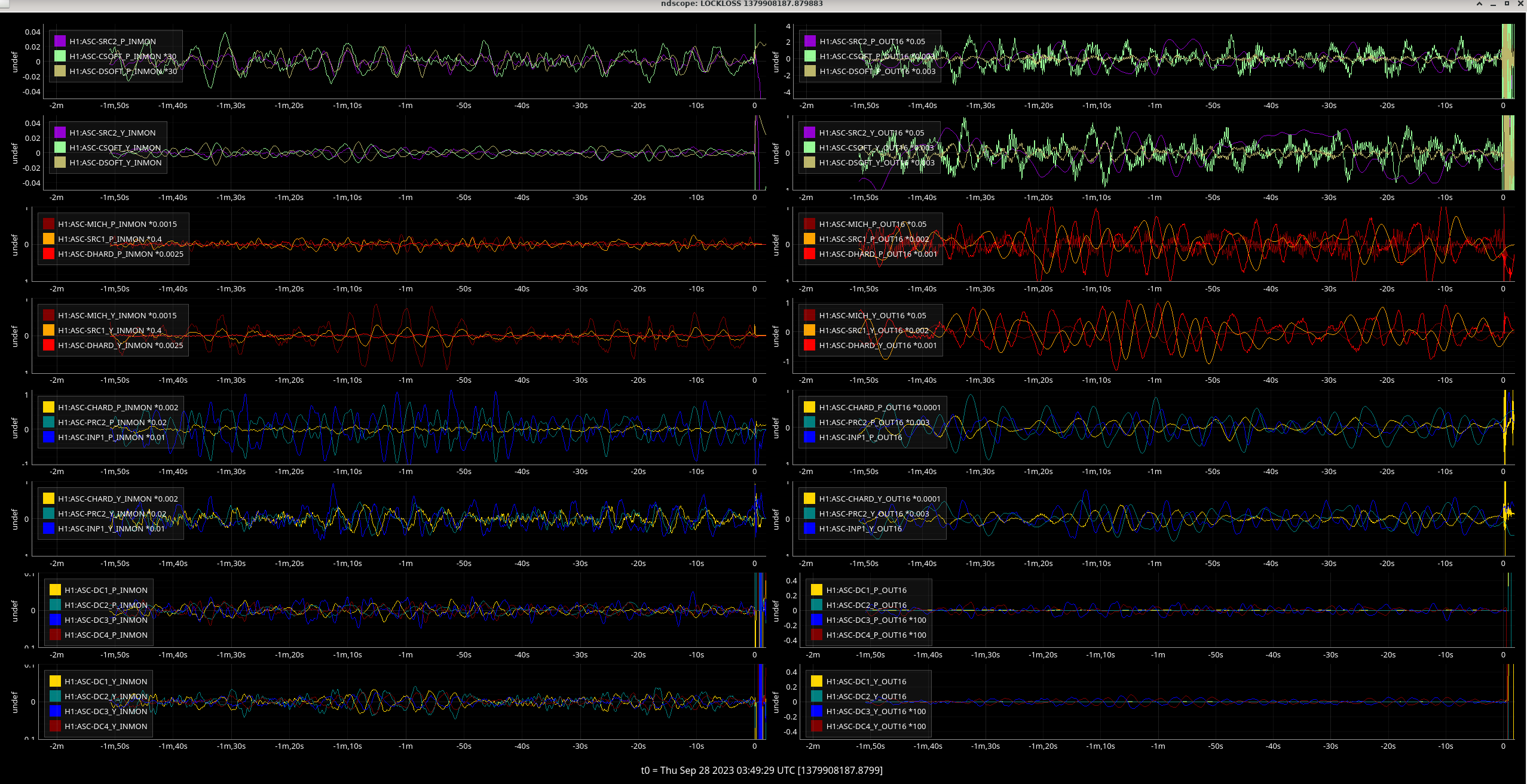
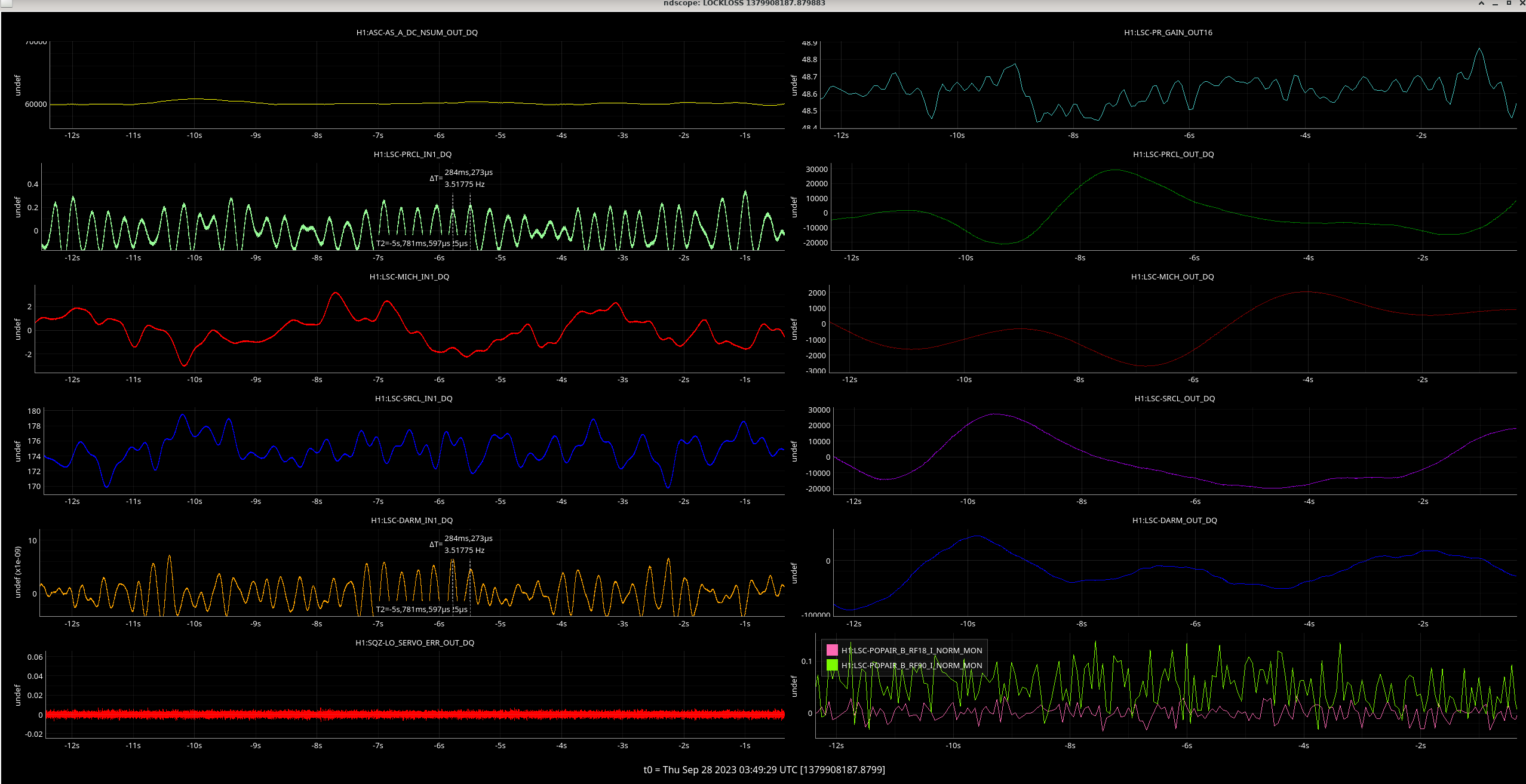
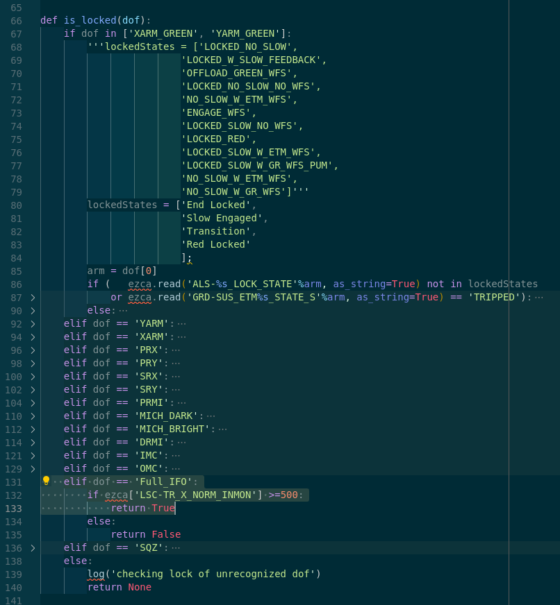
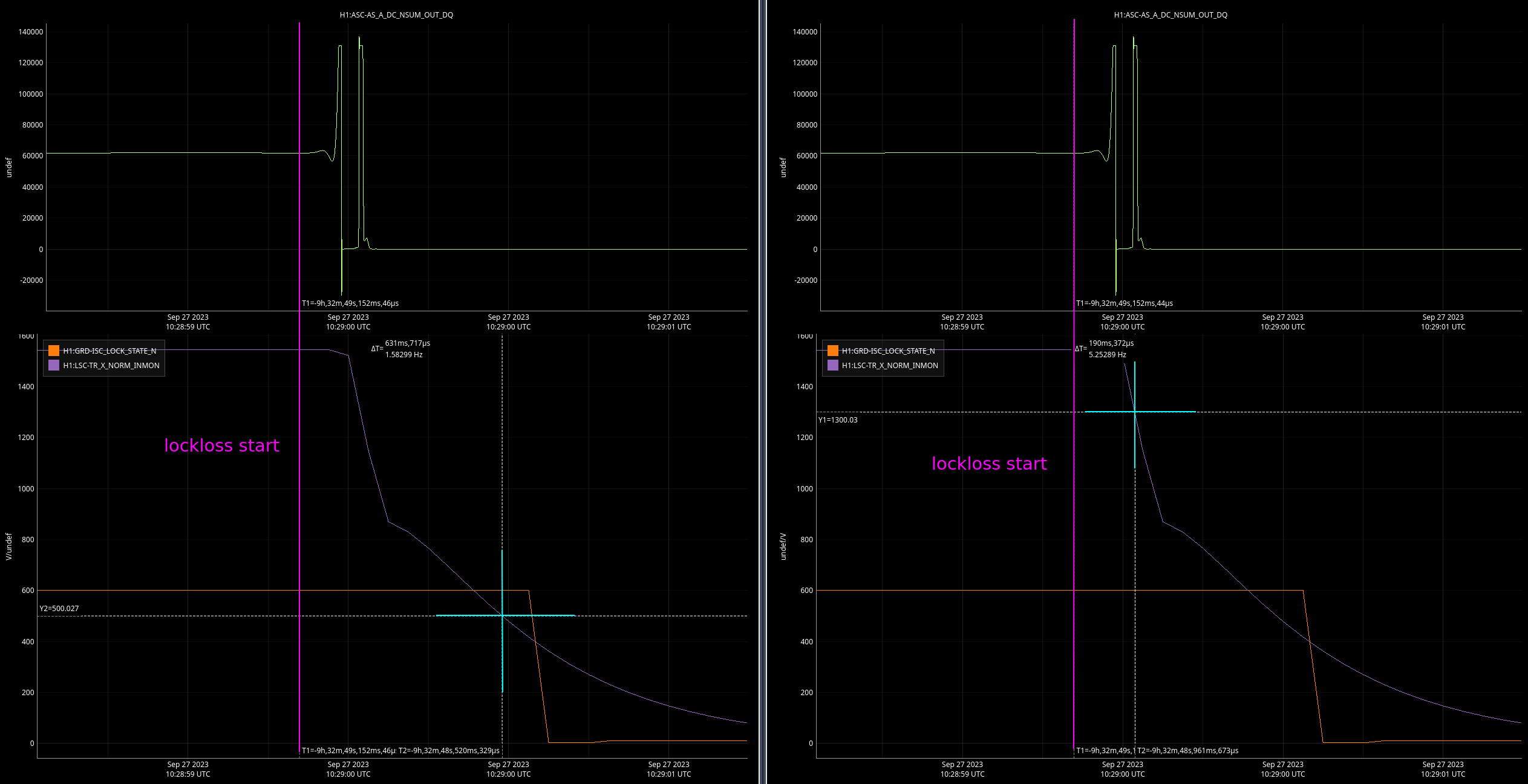
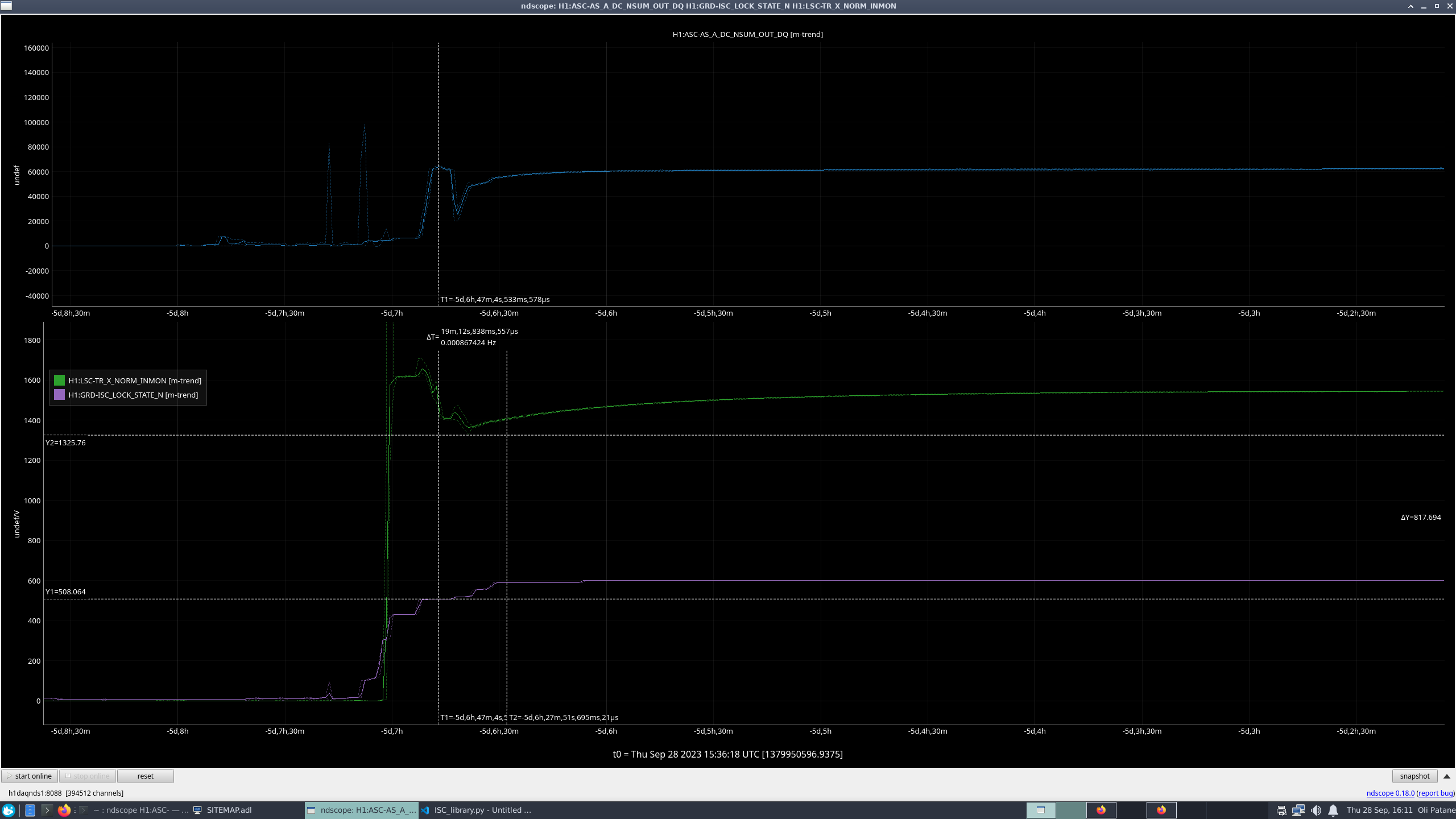
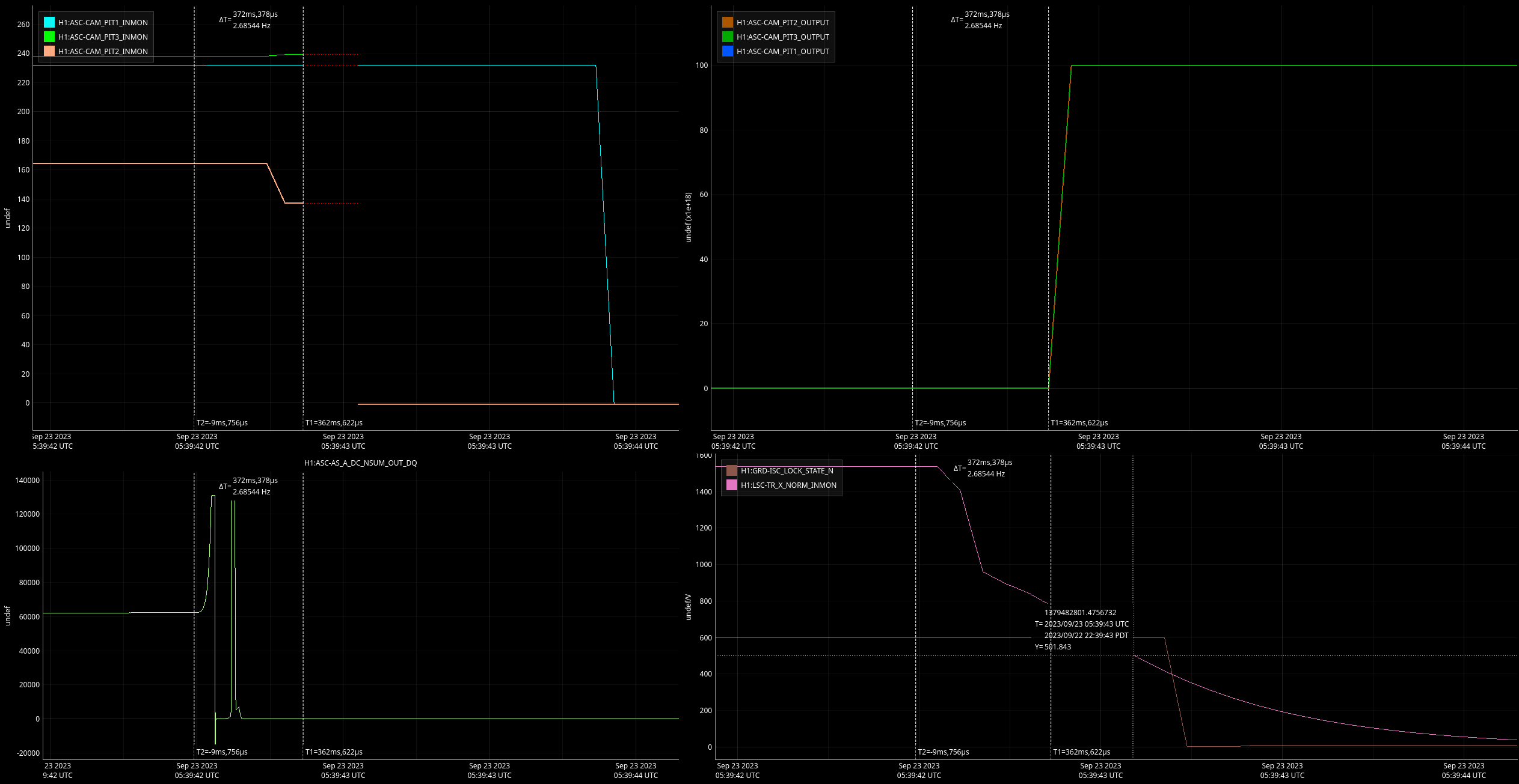
17:45UTC lockloss
17:50UTC Yarm struggled on the relock. We kept losing Yarm at LOCKING_ALS and losing lock. After about over an hour of trying and seeing the weather forecast calling for it to get worse before it gets better I decided to wait in DOWN for a bit. The corner station was getting gusts of 50mph throughout the afternoon, we could easily hear the wind from the control room.
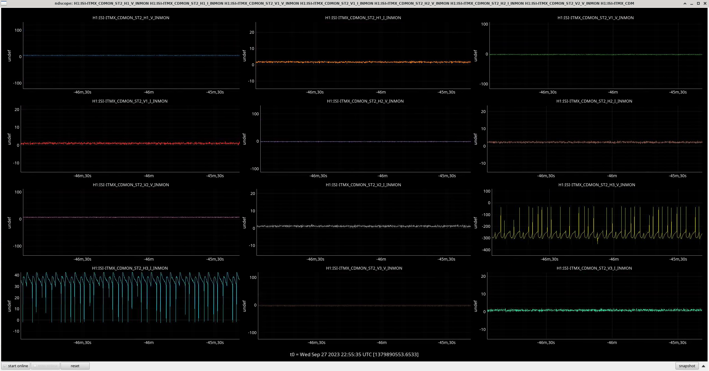
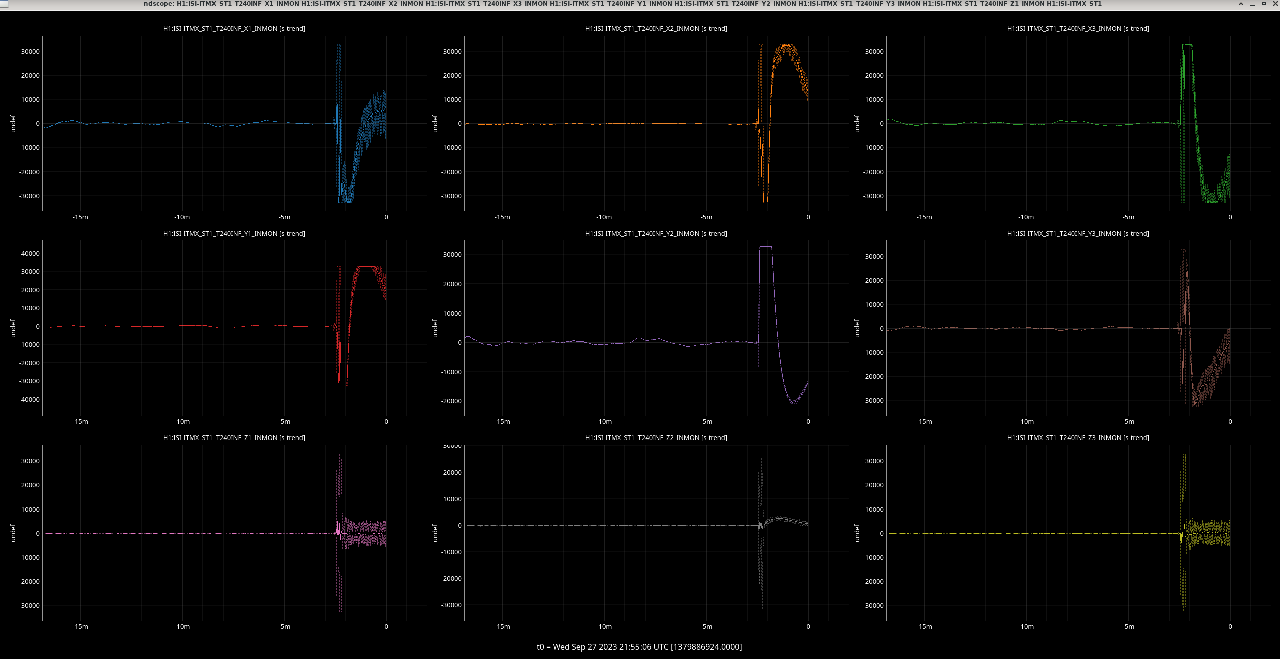
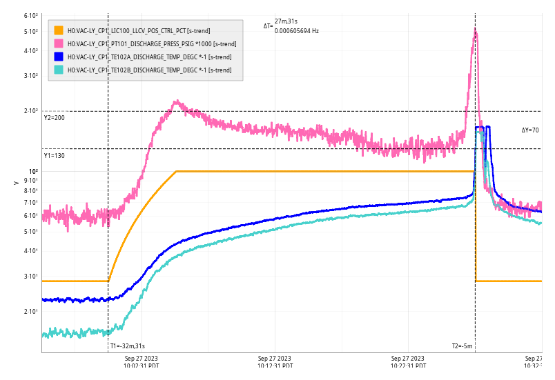
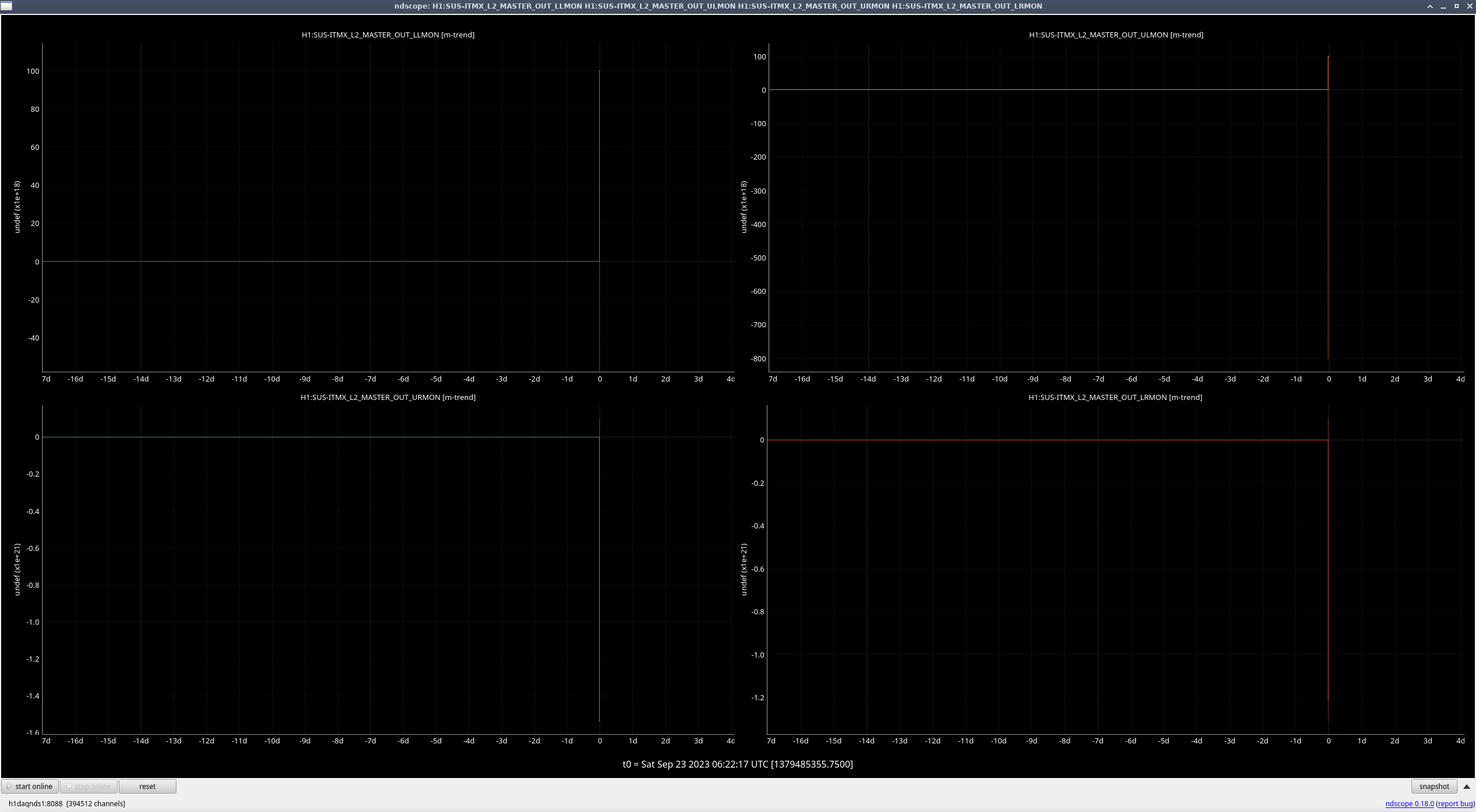
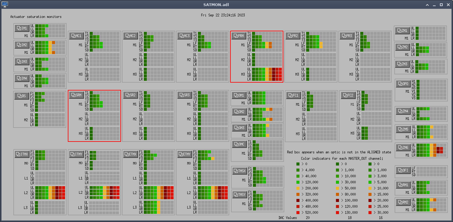
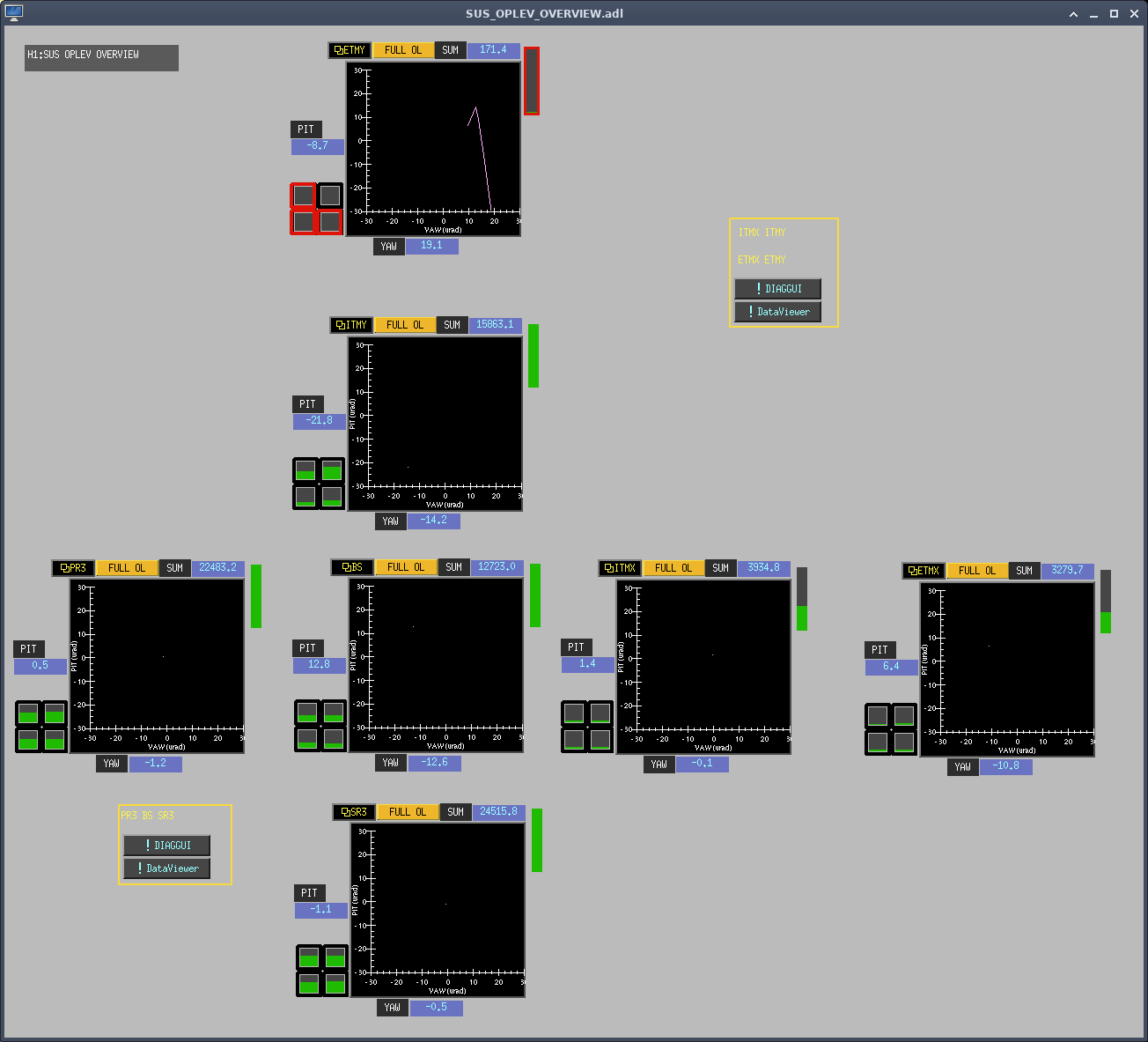
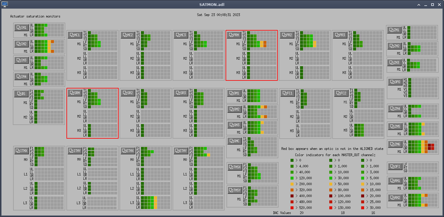
ITMX ST1 & ST2 ISI watchdog tripped at 21:52UTC while we were in down from the ISI senors glitching out. The sensors settled after a few minutes but then continued to glitch, potentially an electronics issue? Fil went to the CER to investigate and I moved ITMX SUS to safe and Jim turned off the master switch on the ISI while we investigate more. Fil did a power cycle of the chassis and it cleared the issue, it seems to have been a coil driver issue? Related to alog71566
LOG:
| Start Time |
System |
Name |
Location |
Lazer_Haz |
Task |
Time End |
| 19:56 |
FAC |
Randy |
LVEA |
N |
Quick checks |
20:05 |
| 21:18 |
VAC |
Gerardo |
FCES |
N |
Parts search |
21:45 |
| 21:34 |
FAC |
Randy |
Mech room |
N |
Move stuff around |
22:34 |
| 22:16 |
EE |
Fil |
CER |
N |
ITMX ISI checks |
22:30 |


