david.barker@LIGO.ORG - posted 10:13, Tuesday 27 January 2026 (88912)
Tue CP1 Fill
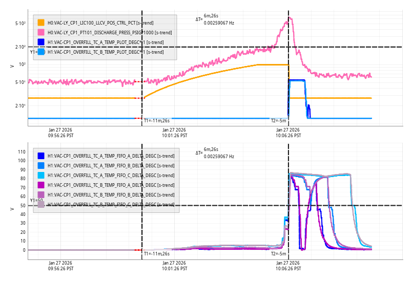
Tue Jan 27 10:06:26 2026 INFO: Fill completed in 6min 22secs
Images attached to this report
Tue Jan 27 10:06:26 2026 INFO: Fill completed in 6min 22secs
Karmeng, Betsy, Jeff, Rahul
Following the recommendation given in LHO alog 88872, yesterday (01/26/2026, Monday) we went into HAM7 chamber and re-centered the three horizontal AOSEMs (H1, H2 and H3) as best as we could. All three AOSEM counts (raw inmons) are now between 11-15k.
Next, Jeff will re-take the transfer function measurements and confirm if OPO is healthy.
Also, Sheila et al will re-confirm if the beam is well aligned with other suspension in HAM7 chamber.
OPO is currently unlocked and suspended.
Because there was some confusion about the mechanical states in the corner station, I'm posting a summary of things as they stand today. The only HEPIs that are locked are HAM1,2 and BSC2, and HEPI Isolation are still bypassed. The white board in the control room says HAM1-4 are locked, this is not true. I have re-enabled the isolation loops for HAM3 HEPI (set H1:HPI-HAM3_ISO_GAIN to 1) and set HAM3 SEI back to ISOLATED. HAM1&2 HEPI are still bypassed. HAM1 & 7 ISI are also still locked.
HAM1,2, BSC2 HEPI - LOCKED, BYPASSED
HAM1,7 ISI - LOCKED
Everything else should be able to be run as normal.
WP12997 Jonathan, Erik, Dave:
The cdswiki server, which actually is now just our CDS Apache web server after the wiki moved to GC, was physically moved from MSR-RACK12 [U17,18] over the MSR-RACK11.
We decided to put it where the unpowered netmonitor machine was in U16,17. The netmonitor machine was removed and is now in H2 storage.
cdswiki has only a 10.20 ethernet cable connection, I used a shorter 6-footer (E5B-006-0001) which was dangling in the rack.
TITLE: 01/27 Day Shift: 1530-0030 UTC (0730-1630 PST), all times posted in UTC
STATE of H1: Planned Engineering
OUTGOING OPERATOR: None
CURRENT ENVIRONMENT:
SEI_ENV state: MAINTENANCE
Wind: 4mph Gusts, 3mph 3min avg
Primary useism: 0.03 μm/s
Secondary useism: 0.33 μm/s
QUICK SUMMARY:
IFO is in IDLE due to PLANNED MAINTENANCE
Work continues on in-chamber JAC alignment and EOM work is continuing (RTP installation planned for today). Work is being done to close out HAM7.
Fire pump alarms bypassed for next 4 hours while churn testing is ongoing.
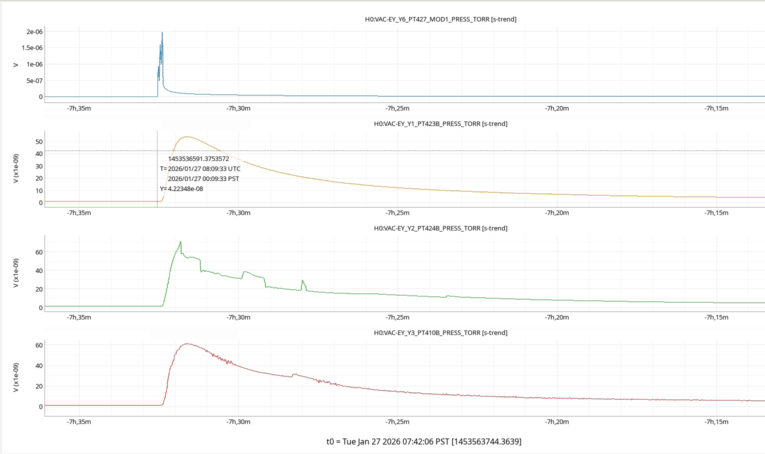
VACSTAT detected a gas release at EY originating at the EY BT Ion Pump and rapidly propagating to EY. Cell phone alarms were sent to team-VAC.
Gerardo determined that the Y2-8 ion pump turned off for 1 min 41 seconds and then recovered.
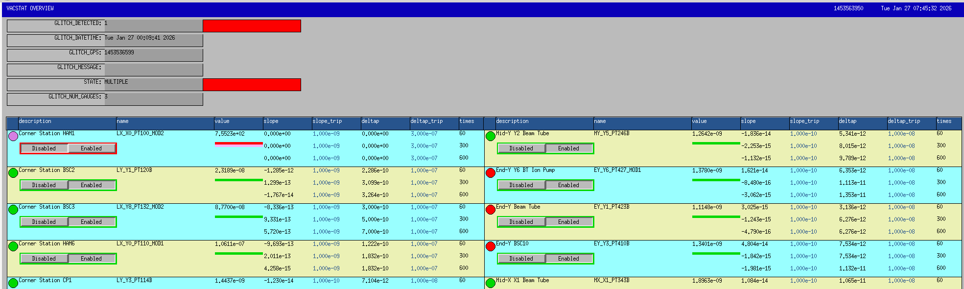
vacstat_ioc.service was restarted at 07:57 to reset this alarm.
Workstations were updated and rebooted. This was an OS packages update. Conda packages were not updated.
Nothing wrong with our previous reflection dip measurements with alumina.
We (MichaelL, StephenA, MattH, Gabriele, Elenna and myself) had a meeting in the morning.
Looking at the "with the alumina" reflection screen shots, Michael didn't see any serious problem so we decided that the electrode-crystal-face plate capacitance is OK. We won't worry about that, we'll just make sure that there's no visible gap.
Third mounting method ("in-between") was proposed and tested.
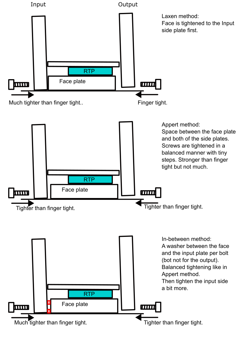
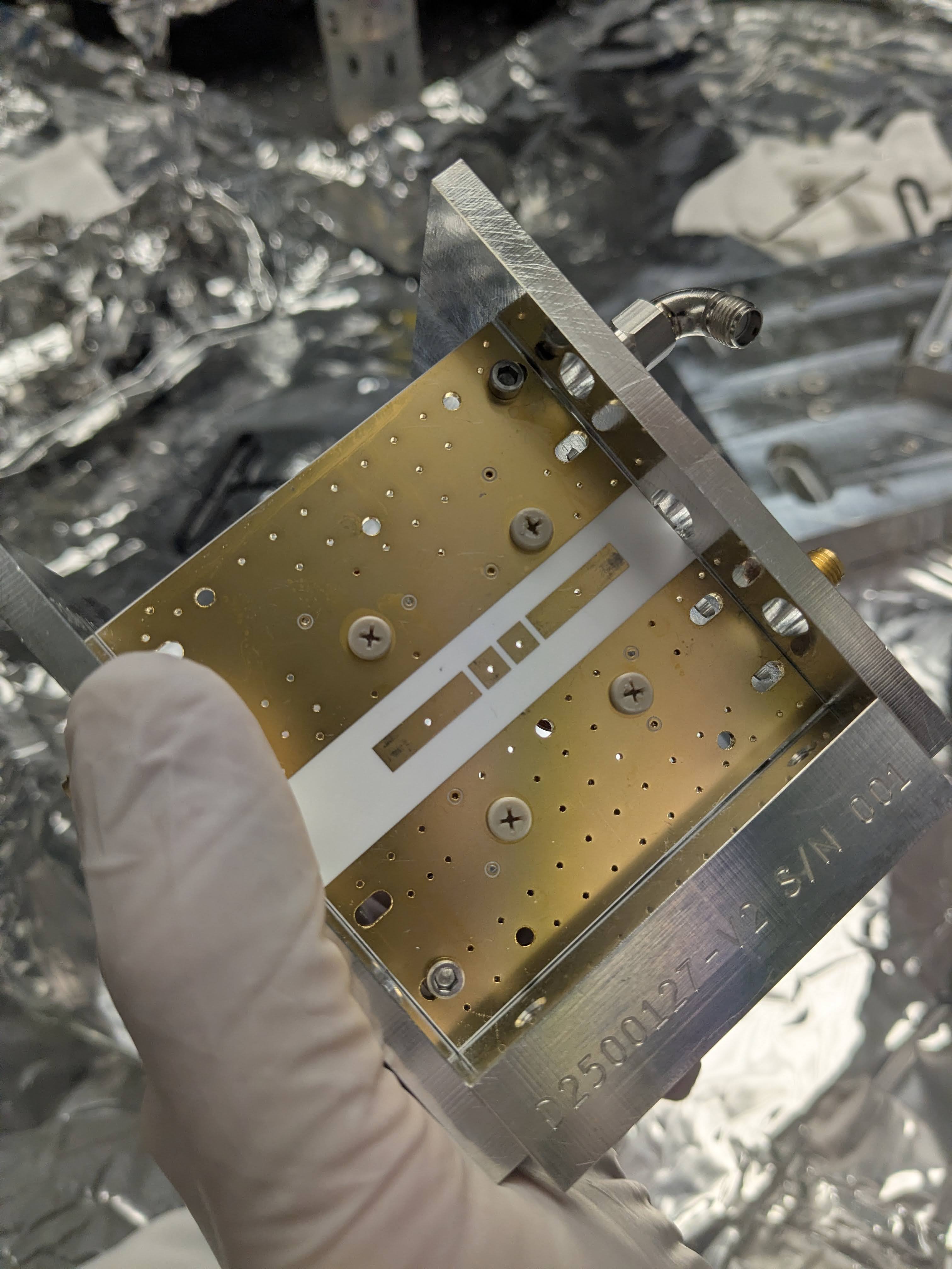
Stephen proposed an in-between method where we use washers between the input side plate and the front plate (bottom of three_methods.png cartoon). After the washer contacts the face plate AND the input side plate, screws are gently tightened in a balanced manner like in Appert method. (In a retrospect this is not that different from Laxen method except the way screws are tightened and that the input side plate contacts with the face plate at two points.)
We first tried to use a presicion thickness shim washer for 1/4-20 screws but I didn't like that they're too big. We ended up using smaller stamped washers that is 0.039" or 0.99mm thick (according to the caliper). That's not flat but seems OK to me.
This in-between method worked in that it was doable and gave us a reasonable reflection dips.
Mechanical stability test of Appert method and in-between method. The latter is better, we'll use that for the real RTP.
My original concern for the original Appert method (middle of three_methods.png cartoon) was that somehow the screw gets loose during transport or after a large change in the in-chamber temperature and the tuning will be off. Upon hearing this, Stephen proposed a test to loosen one screw and see if the tuning changes. We performed this test for both Stephen method and the in-between method. (Spoiler: yes.) We measured all four dip frequencies right after the alumina piece was mounted but only tracked the frequency change of 118MHz peak.
Loosening one screw changes the frequency, but the frequency change for the in-between method is an order of magnitude smaller (10 to 30kHz) than the original Appert method (300kHz) when the FWHM (or rather the width between the points where reflection is 6dB larger than the bottom of the dip) is about 70kHz or so. This is just one trial but I'm convinced that in-between method (or maybe Laxen method too though we haven't tried) is better, so that's what we'll do for the real crystal.
We only loosened the screws on the output side for both mounting methods.
| Initial four frequencies | Shaking? | Loosen 1st screw | Loosen 2nd screw | |
| In-between method |
9.142, 24.110, 45.972, somewhat smaller than 118.214kHz |
changed to 118.214kHz, unclear why. (Something like 10k or 20kHz change, couldn't cause another change by gentle tapping.) |
118.214 -> 118.240 (+26kHz) |
118.240 -> 118.251 (+11kHz) |
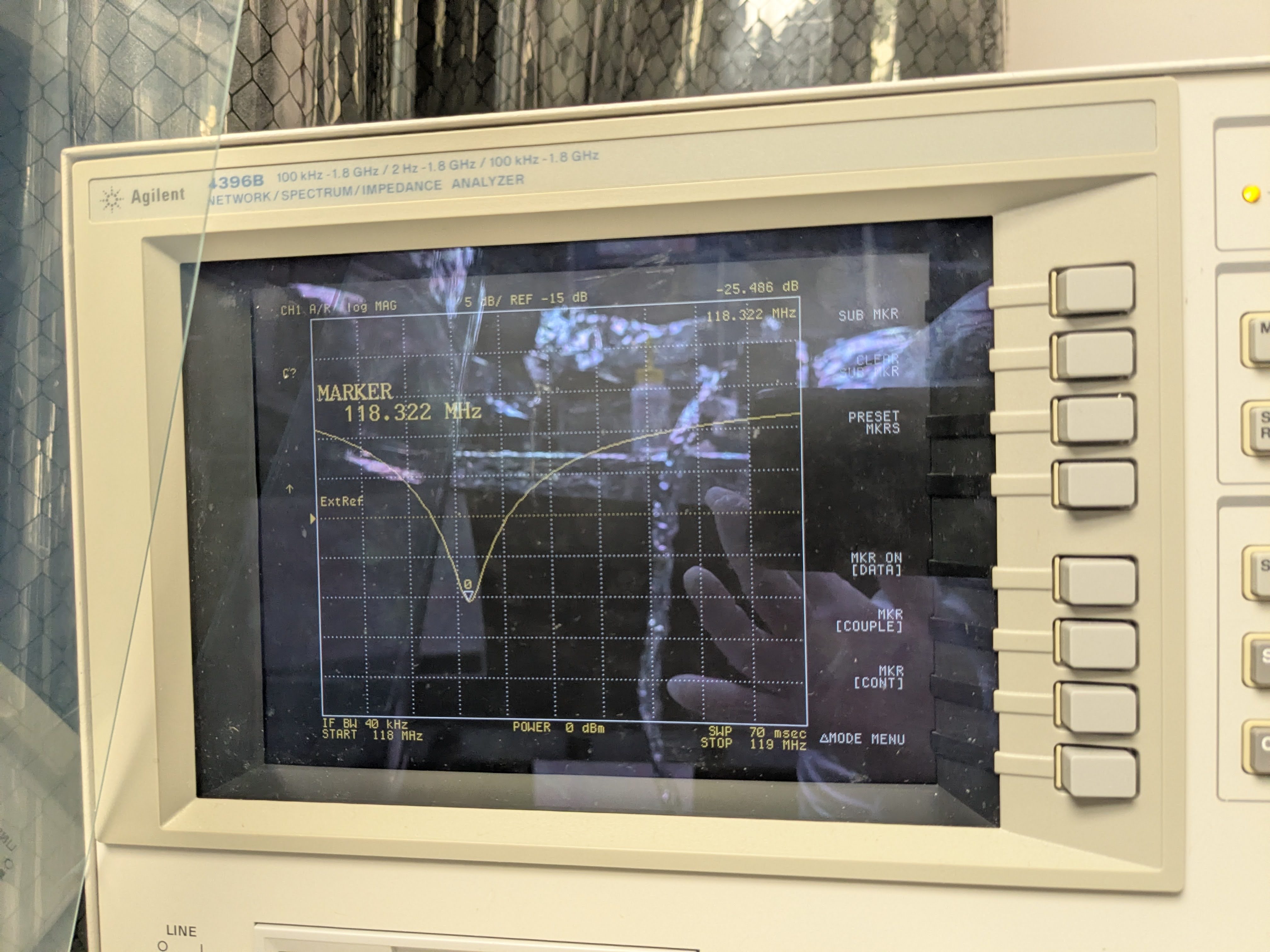
| Original Appert method | 9.14685, 24.107, 46.066, 118.322 |
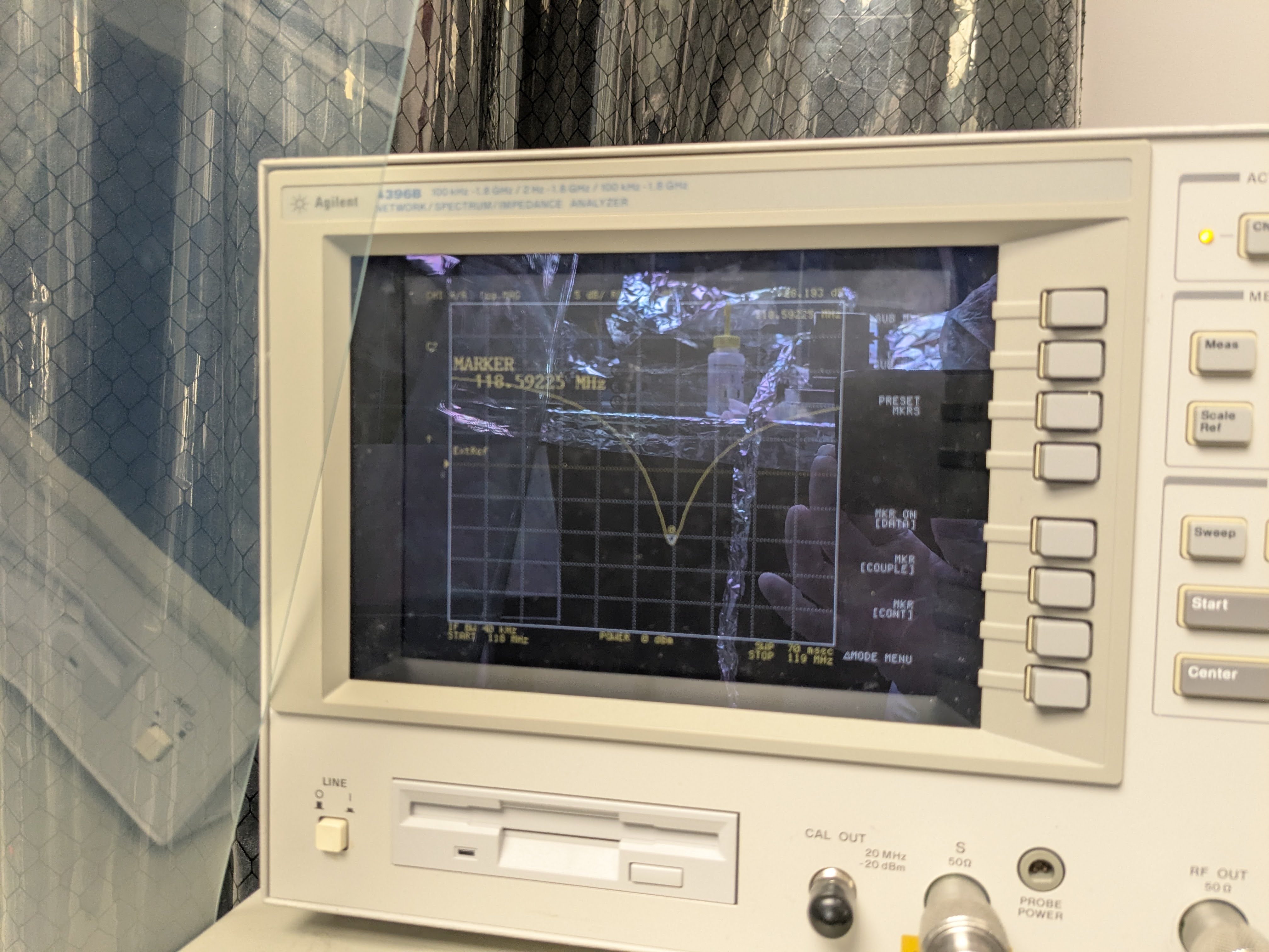
118.322 -> 118.592, caused by gentle tapping. (+270kHz) |
118.592 -> 118.876 (+284kHz) |
118.876 -> noman's land (>1MHz) |
Shake and it will shift, we need to measure it again in chamber?
It's good to know that the in-between method can somewhat withstand the loosening of the second screw (because the tighter screws still support the face plate). However, it's disappointing to find that the assembly is susceptible to shaking.
In the in-between method, we couldn't record the initial 118MHz dip because it jumped up by 10kHz or so in front of our eyes when we were moving around the table. Not sure what happened but I assumed that it was some kind of shaking. However, I gently tapped the front and side plates and couldn't cause another shift.
In the original Appert method, since we knew something could happen, I tapped the front and side plates and there was a huge jump. See the difference between initial_118.jpg and taptap_118.jpg.
Even though we'll use in-between mounting method, it's plausible that the frequency shifts during transport or when the EOM lands on the ISI surface. I'm thinking we'll have to measure it in situ after everything is tuned in the lab.
What's to come tomorrow.
We'll install RTP and tune. Before doing that, though, I'll discuss inserting indium foil between the crystal and the front plate with Masayuki. Michael suggested that (and even between the crystal and the electrode, though that would be tricky) today, Masayuki and I talked about the possibility briefly last week, it just sounds like a good thing as a buffer to absorb gaps here and there.
Other things.
In the previous alog (88886) in one of the pictures (gap.jpg), there was a time when it looked as if the circuit board was slightly bowed. We took a picture of the electrode today (electrode_contactpoint.jpg) and it looks as if the electrode is more abraded close to the outside edge of the crystal, so maybe the board bowing is real.

Why (change in) the gap might matter.
Gabrilele asked me why a tiny gap matters so I made a quick calculation.
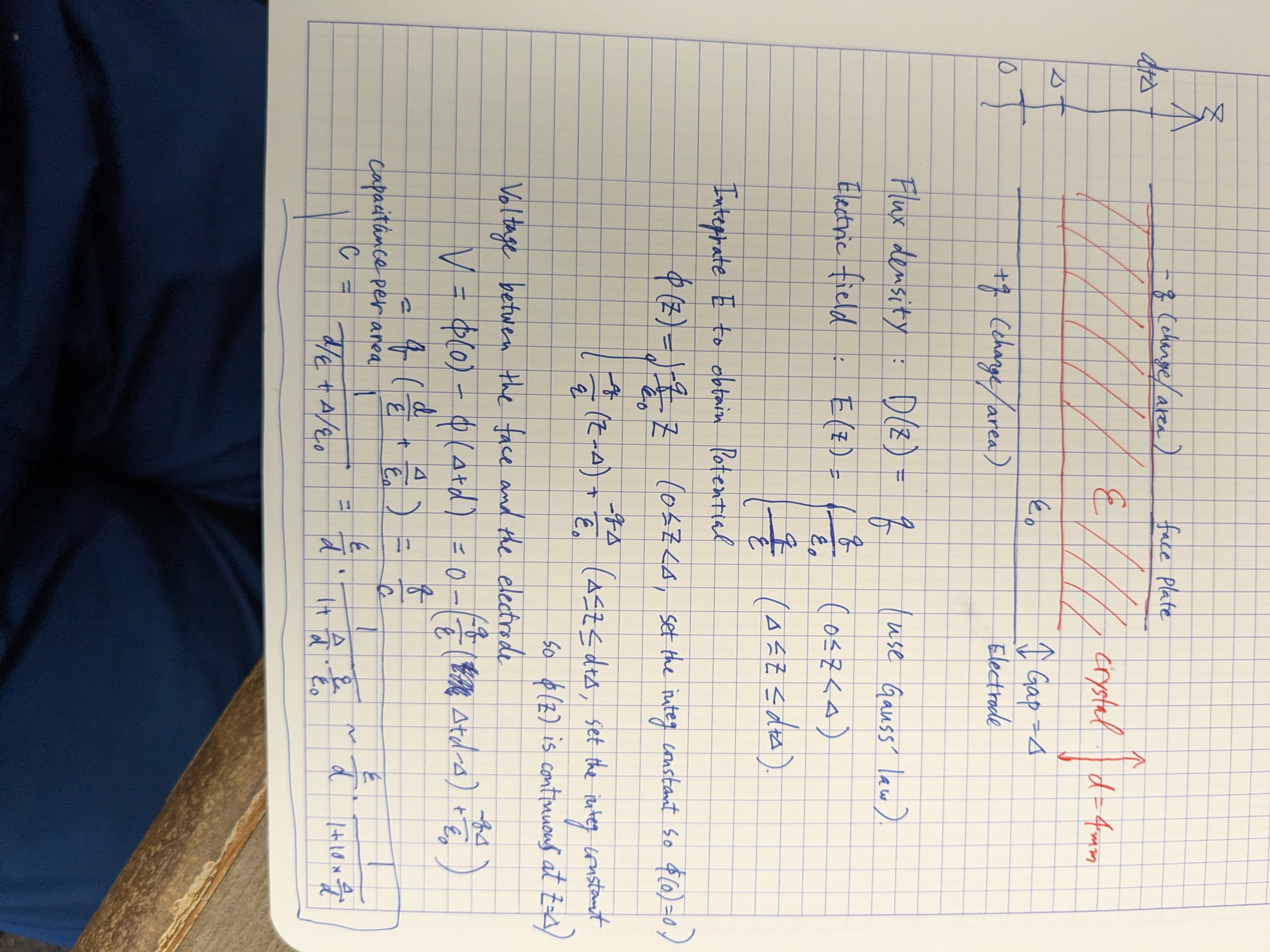
Suppose that we can ignore the edge effect at the edge of the electrode for convenience, we can replace the 4x4x40mm crystal with an infinitely wide and long crystal that is 4mm thick, and replace the capacitance with the capacitance per area.
In the attached, the electrode, the crystal and the face plate are all inifnitely larger in a plane orthogonal to the surface of my log book. Thickness of the crystal is d (4mm). There's a gap of delta between the electrode and the crystal, and there's no gap between the crystal and the face plate (but it's not important where exactly the gap is).
Under such a configuration, if you do the math, the capacitance per area is equal to the no-gap capacitance per area multiplied by 1/(1+epsilon*delta/epsilon_0/d) where epsilon and epsilon_0 are the permittivity of the alumina and vacuum, respectively, and the former is 10 times the latter.
In the end, the capacitance with the gap is a factor of
1/(1+10*delta/4mm)
smaller than without the gap.
The capacitance with a 0.1mm gap is 80% of that without the gap, 0.2mm and it's 67%, 0.3mm (12 thou) and it's 57%. If the gap doesn't change, maybe that's OK. If the gap changes it will change the tuning via capacitance change. There are other effects (like coil winding) but the capacitance change via the gap change cannot be ignored/dismissed.
Jennie W, Sheila D, Rahul K
Summary:
I guess the summary for yesterday is we improved the input alignment to JAC but are not sure why it was lower relative to last Thursday.
And that we have aligned into the IMC with steering mirrors after JAC on HAM1 and now get TM00 modes flashing on the IMC TRANS camera but are not sure why our on-table references (IMC REFL WFS) and in-chamber iris are not aligned with this beam.
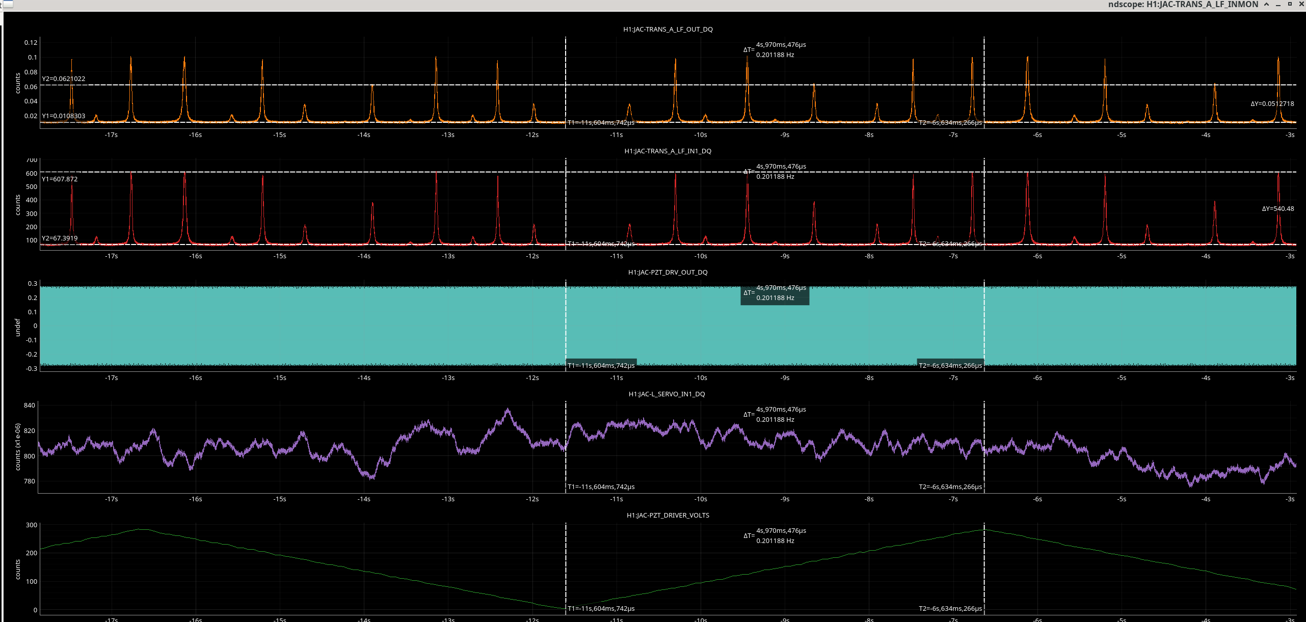
Before we went into chamber today we checked the fringes in the JAC cavity transmission to see if we had the same power in the TM00 modes as Friday (when it was ~ 0.15). From the image you can see that the level on the JAC-TRANS_A PD is now around 0.1, and it looks as though the 01 mode could be near the size of the TM00 mode.
This implies the input alignment (which we recovered on Thursday to 0.22) has been drifting.
In chamber Sheila found that the JAC cavoity was locking on a 01 mode (two vertical lobes).
She tried moving the JM1 mirror and found the base was slightly loose in the mount. Not sure if this is enough to really explain the mis-alignment fully.
She tweaked up the alignment of this mirror and I tweaked up the alignment using PSL PZT periscope mirror until the beam went up to 0.22 on the JAC TRANS A PD.
We checked the power in chamber right before the input coupler to JAC and it is now 93 mW.
The power measured after JAC (right before mirror JM2) is 58 mW.
The power measured on IOT2L after the bottom periscope mirror is 44mW.
After continuing tweaks to the input alignment we got 0.28 on the JAC TRANS A PD 0.28 with input alignment changes.
We maximised the power onto the table by moving JM2 and JAC-M3 and looking at the IMC REFL PD.
We have 76mW power after bottom periscope mirror and
a 0.96 - 1.2 level on MC REFL PD.
Still have 0.28 level on JAC trans out.
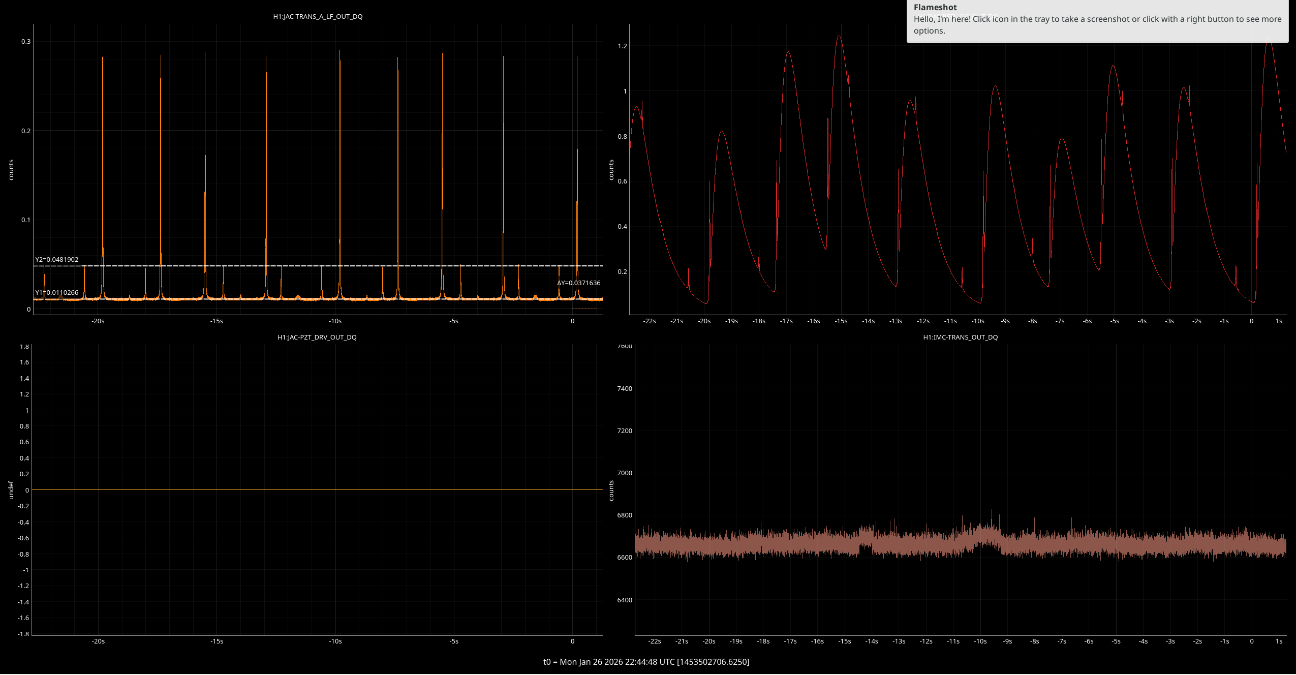
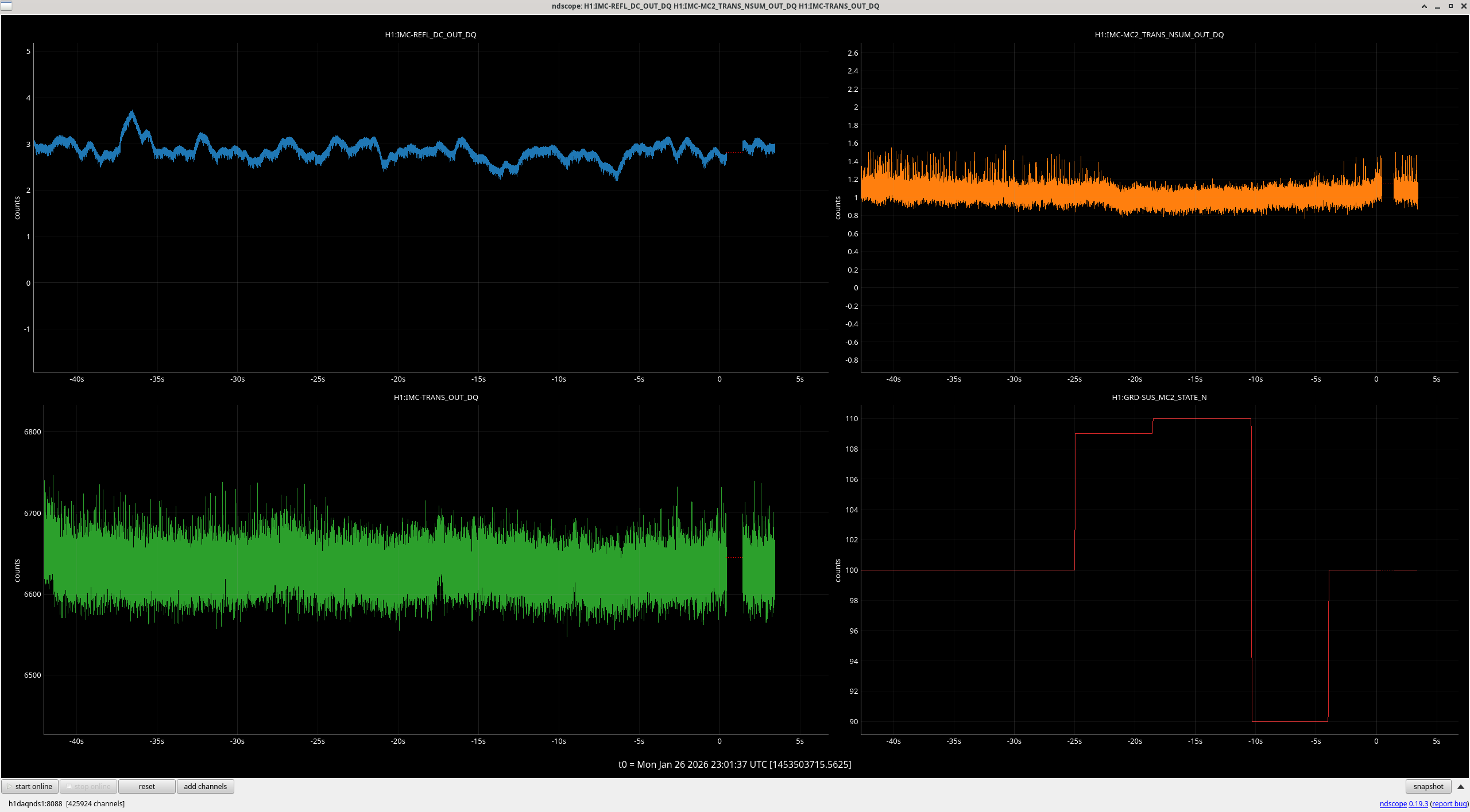
We started to notice fringing (see image) on the IMC TRANS camera and on MC2 TRANS QPD NSUM.
I did a quick check of the mode-matching and it looks like our mis-match is now about 11% (for the second highest mode in the scan).
We therefore switched to using these as our metric while we optimised the alignment into the IMC with the same two mirrors JAC_M3 and JM2.
Eventually Sheila and Rahul discovered clipping on the last iris before the beam leaves HAM1 so marked the height with a C clamp and took it out. This was our reference for the original beam into HAM2 before the JAC install was started.
Continued to optimise with these two mirrors.
At the end of the day we placed new iris after output periscope and moved iris on IOT2L in reflection of first table steering mirror to mark the placement of the beam.
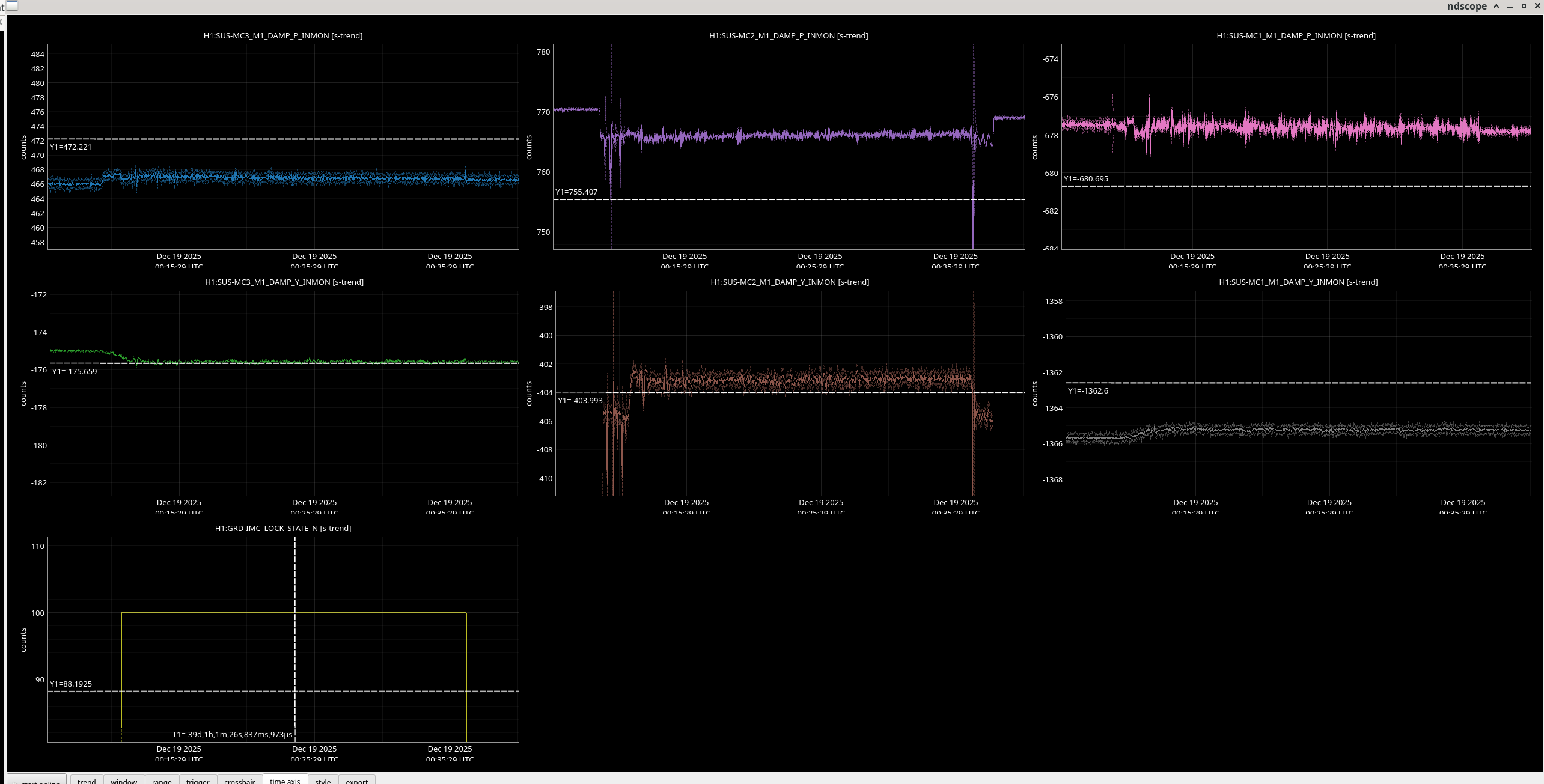
Since we still are not aligned to our references on the table - ie. the WFS, the iris placed at the HAM1 output before JAC was installed, we will double check the MC mirrors position relative to our most recent in-air lock and the last in vacuum lock.
Compared to the 19th December 00:25 UTC, the position of MC3 M1 DAMP INMON has increased by 6 uradians in pitch and has not changed in yaw.
Compared to the 19th, the position of MC2 M1 DAMP INMON has decreased by 10 uradians in pitch and has decreased by 1 uradian in yaw.
Compared to the 19th, the position of MC1 M1 DAMP INMON has decreased by 3 uradians in pitch and has increased by 3 uradian in yaw.
Cursors show current values in this ndscope plot.
Jeff also did a check here (alog #88895).
S Muusse, M. Todd
New QCL unit (0920) has been put in place of original unit (0923) which is malfunctioning (cause unknown). Initial profiling has taken place and L1 focal length is 10% larger than spec.
QCL unit failure summary:
All day on 2026-01-21 we were running the laser at 900mA doing beam profiles and alignment work. No malfunctioning was witnessed and the laser unit was operating as expected, similar to the laser unit we had run in December for a week. Before lasing we set the following limits on the LD and TEC, per the datasheet.
On 2026-01-22 we turned the laser on to do some more beam profiling with the same limit settings as yesterday, but setting the LD current to 1A (forward voltage was around 12.2V) as was done when we originally profiled this laser in September. We were in the middle of setting up for a new beam profiling measurement (alignment showed the beam was fine, as usual) and we blocked the beam with a high power beam dump at the laser head while installing the profiler. Upon removing the beam dump, we noticed no power was coming out of the laser, and then noticed the forward voltage had dropped to around 800mV. We noticed no sounds or smells or any other signs that something had stopped, only sudden lack of light coming from the unit. All other settings were fine, meaning the controller had not faulted and was still outputing 1A LD current and the TEC was maintaining 20C.
We ran the following checks to see if we could remedy the problem, without success.
QCL 0920 profiling summary:
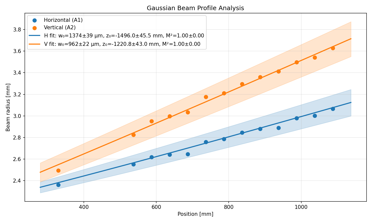
Replaced broken unit with 0920 and confirms it lases as spec'd. We built telescope as modelled but beam profile was 75% of expected beam width at L2. We subsequently profiled the laser output and confirmed QCL output q measured previously by Matt was still correct. We became suspicious of the true focal length of L1. Then we profiled multiple places after L1 and fit a q parameter using a non-linear fit. A plot of this fit is attached. Using these 2 q parameters the focal length of L1 was estimated to be 220mm instead of 200mm as spec. We think this is mostly because L1 focal length stated by manufactorer is for 588nm where the refractive index is almost 3% larger than at 4.6um. Focal length in the model was modified to reflect our estimated f1 which predicted a beam size closer that measured earlier.
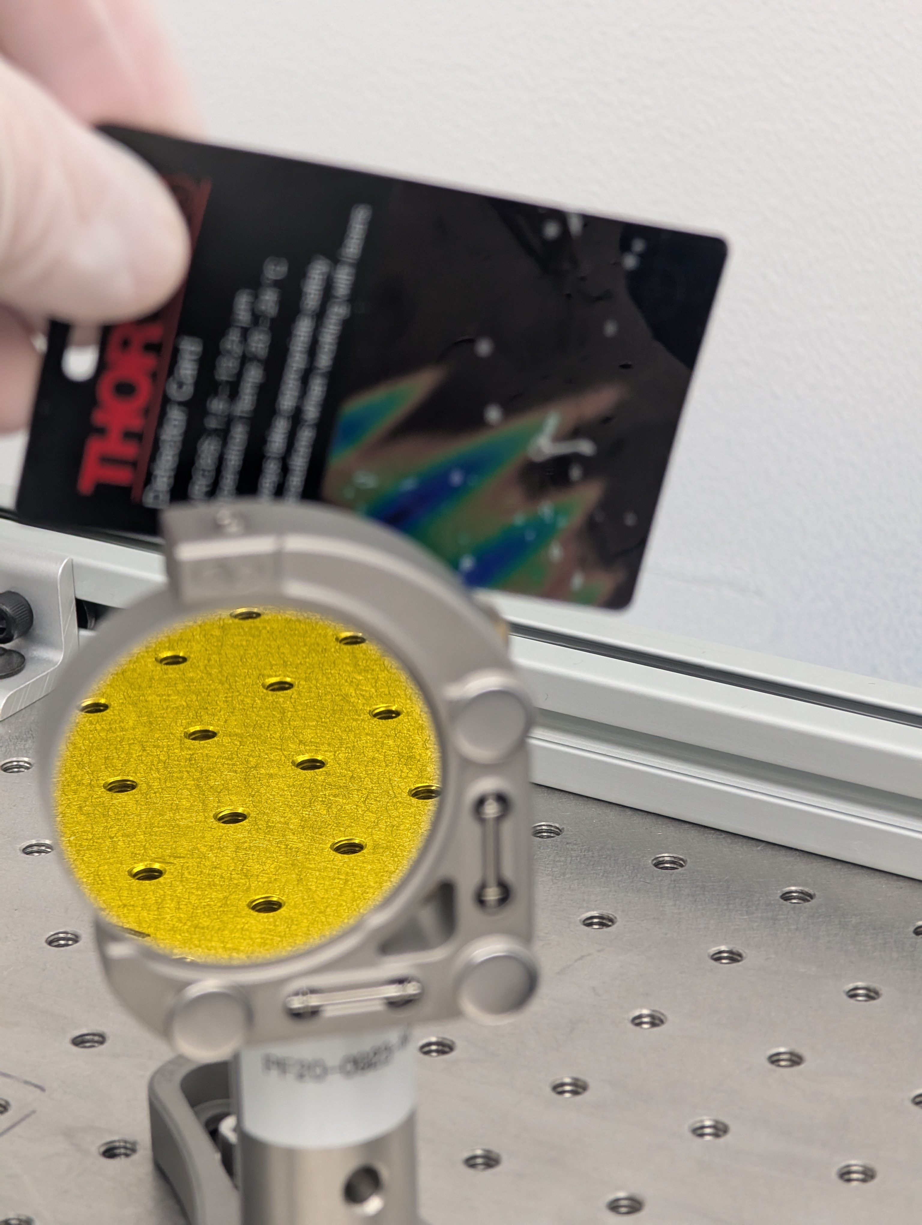
Side note: the scanning slit beam profiler reflects significant amount of 4.6um light which is observable on a thermal beam card.

This morning we continued profiling to characterize the true L2 focal length and install the modeled telescope and characterize it.
We replaced L1 with L2 in the telescope and made several measurements to fit for a q-parameter after L2, because we think we know the q going into it quite well. Then with the q parameters, you can estimate the focal length using ABCD matrix for a thin lens (our estimates yield relatively low complex angles, less than 1 deg, making confident estimates).
| Parameter | x [m] | y [m] |
| Input q (coming from the laser) | 0.411 + 0.067i | 0.376 + 0.056i |
| Output q (fit from profiles) | 1.496 + 1.289i | 1.221 + 0.632j |
| Focal Length (-q1/(q1/q2 - 1) | 0.503 | 0.511 |
Average focal length of L2 = 0.507 m. Which is around 1.5% different from the spec'd value. To reiterate Sophie's log above, the focal length of L1 is estimated to be 0.217 m. Which is almost 9% different than the spec'd value. With these values in hand (as well as the updated value for CaF2 refractive index at 4.6um), we can make a more accurate model and see if measurements of the outgoing q-parameter from the telescope match that model.
We installed a telescope as set up in a model and measured several proviles to fit for the q-parameter after L2. The modeled waist size in both the horizontal and vertical are within the fit uncertainty; however the waist position of the modeled beam is roughly 20cm off in both directions. I think this is because of the Gouy phase regime that we are sampling gives better estimates of the waist size and since we did not sample near the waist we do not have a good idea of where it is.
This afternoon we will try and re-build the telescope as optimized in our models with these measurements to see if we can get a q-parameter that will be 53mm at the "ITM" (propagated 35m from L2).

Jonathan, Dave, Erik,
We started on WP 12998. After doing WP 12997 we had freed up the space we needed to install the new VM hosts.
What we have done so far is to move the computers and the associated switch from the test stand and rack mount them in rack 12 in the MSR. Jonathan has started the reconfiguration of the switch.
Todo tomorrow:
The new computers will be pve-node[0,1,2] and the switch is sw-msr-pve0.
TITLE: 01/27 Day Shift: 1530-0030 UTC (0730-1630 PST), all times posted in UTC
STATE of H1: Planned Engineering
INCOMING OPERATOR: None
SHIFT SUMMARY:
A very productive day with the following activities:
1. EOM - Work continued on the EOM in the Optics Lab.
2. HAM1 - MC Trans has been recovered! Meaning that light has been aligned from the input through the JAC to the Mode Cleaner!
3. HAM7 - OPO work is continuing.
4. VAC - Relay tube work ongoing.
LOG:
| Start Time | System | Name | Location | Lazer_Haz | Task | Time End |
|---|---|---|---|---|---|---|
| 22:49 | SAF | LVEA IS LASER HAZARD | LVEA | YES | LVEA IS LASER HAZARD \u0d26\u0d4d\u0d26\u0d3f(\u239a_\u239a) | 16:49 |
| 15:57 | FAC | Kim, Nellie | LVEA | Y | Technical Cleaning' | 16:19 |
| 16:49 | OPS | Corey | Optics Lab | N | Part Search | 17:03 |
| 16:58 | FAC | Kim, Nellie | LVEA | Y | Technical Cleaning | 17:49 |
| 17:19 | FAC | Randy | LVEA | Y | BSC2 Platofrm Work | 18:44 |
| 17:23 | COC | Keita | Optics Lab | N | EOM Work | 20:22 |
| 17:35 | VAC | Travis, Jordan | LVEA | Y | Relay Tube Work | 19:30 |
| 17:46 | SQZ | Jennie | LVEA | Y | Opening PSL Light Pipe | 17:48 |
| 18:12 | SUS | Betsy | LVEA | Y | HAM7 OPO | 22:29 |
| 18:12 | SUS | Rahul | LVEA | Y | HAM7 OPO | 21:51 |
| 18:23 | COC | Jennie | LVEA | Y | HAM1 | 21:51 |
| 18:49 | FAC | Randy | LVEA | Y | HAM7 Help | 19:31 |
| 18:59 | JAC | Elenna | Opt Lab | N | EOM work | 19:59 |
| 19:12 | OPS | Corey | Optics Lab | N | Parts | 19:23 |
| 19:27 | ISC | Matt | Vac-Prep/JOAT Lab | N | Checking on laser | 21:51 |
| 19:42 | SUS | Kar Meng | LVEA | Y | HAM7 | 18:42 |
| 21:35 | PCAL | Tony | PCAL Lab | N | Meas. prep | 23:34 |
| 21:52 | COC | Keita, Elenna | Optics Lab | N | EOM | 23:40 |
| 22:18 | ISC | Matt, Sophie | Vac-Prep, JOAT | N | Checking on laser (CHETA) | 22:34 |
| 22:19 | SQZ | Sheila | LVEA | Y | HAM7 | 18:19 |
| 22:20 | VAC | Gerardo, Jordan | MY | N | Part Grab | 23:53 |
| 22:22 | SUS | Rahul | LVEA | Y | HAM1/7 | 22:29 |
| 22:40 | EE | Fil | LVEA | Y | HAM6 Rack Work | 01:40 |
| 23:09 | SUS | Rahul, Sheila, Jennie | LVEA | Y | HAM1 Work | 02:09 |
| 23:10 | ISC | Matt, Sophie | Vac-Prep, JOAT | N | CHETA | 01:10 |
| 23:27 | SAF | Jenne D | Input arm | Look at Ham2 Ham3 layoutg | 23:53 | |
| 23:47 | SUS | Betsy | LVEA | N | HAM1 | 01:47 |
Closes FAMIS 38863. Last checked in alog 88726
Trends similar to post-outage plots from last check.
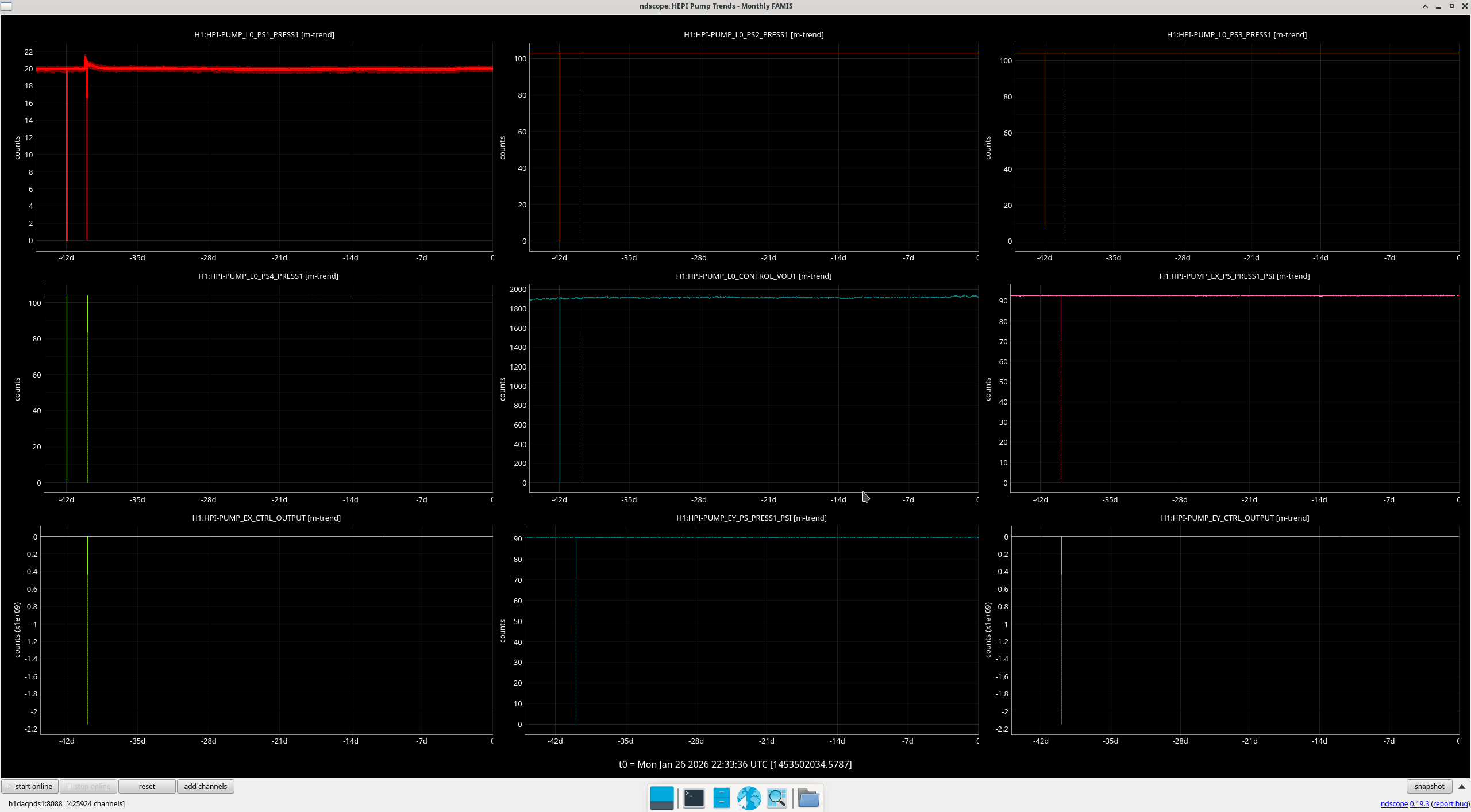
Closes FAMIS 39335, last checked in alog 88829
Comparable to last check. Elevated sensors are the open chambers.
Summary: Scattering studies before the end of O4 suggested that the non-linear vibration coupling that dominates DARM at 20 Hz and contributes significantly up to about 50 Hz, was produced by modulated retro-reflections of the annular beams coming from the bevels of the ITMs and the annular beams from the BS barrel and cage (87758). End-of-run studies, reported here, support these conclusions, and a model estimating scattering noise from vibration time series suggests that reflection from the SR tube MC baffle near HAM4 is also a likely ambient noise source in the unusually high 80-200 Hz region of DARM. The annular beam noise from chamber walls would be mitigated by the already planned ITM cage baffles and the BBS. It is also likely that the HAM4 and SR MC baffle noise would be mitigated by the BBS. The safest route would be to go ahead and install the HAM4 table baffles and treat the HAM4 MC baffle, but we could also wait and see if their noise is mitigated by the BBS.
Noise at 20-50 Hz injection frequencies, likely from 20 and 45 degree annular beams
As noted at the end of alog 87758, the noise in DARM was most consistent with the motions of permanent accelerometers on ITMX, ITMY and the BS, consistent with what would be expected if the annular beams (83050) from optics in these chambers cause scattering noise. We have, since then, mounted temporary accelerometers around these chambers and elsewhere to further test this hypothesis, particularly placing accelerometers on the vacuum envelope at locations just outside of where the annular beams hit the inside of the enclosure.
We used two of the three vacuum enclosure techniques mentioned in 87758, the beating shaker technique and a variant of the consistency test for sweeps from shakers at different locations. However, we were not able to use the third technique, the hand-held shaker test in the region close to the vertex because of magnetic coupling, likely to magnets on the BS, even though the coil is much smaller than those in our other magnetic shakers.
Consistency technique
The accelerometers that were most consistent for 3 sets of 3-shaker injections were temporary accelerometers mounted near where the ITM annular beams hit the bellows of the spool pieces between the ITMs and BSC2, one for each ITM, and the permanent accelerometers “BSC3_Y” and “MCtube”. The BSC3-Y accelerometer is near where the annular beam from the BS likely shines (See Figure 1), but the MC tube accelerometer is probably coincidental because when a shaker was moved to the MC tube, the accelerometer there was no longer consistent with DARM.
Beating shaker technique
The accelerometers mounted just outside where the ITM annular beams hit were also the most consistent with DARM for the beating shaker technique. Figure 1 shows results of one of the most convincing beating shaker tests. A piezo shaker was mounted near where the ITMX annular bevel beam hits the bellows of the BSC2-BSC3 spool-piece (see photograph here ). A second shaker was mounted on the old H2 BSC7. The shakers were set to 31.005 Hz and 31 Hz respectively. The amplitudes of the two shakers were adjusted so that each individually produced the same amplitude of peak in DARM, before they were both turned on. Figure 2 shows that the timing of the beat envelope of the accelerometer on the bellows where the annular beam hits, matches the beat envelope timing in DARM, while timing for 14 other accelerometers that I examined (7 are shown) did not match as well. Also, the modulation depths of the beat in the accelerometer signals are greatest in this region of the enclosure, indicating that the two shaker peaks have similar amplitudes in the accelerometers near this location, like the two peaks in DARM (by adjustment).
Potential noise at 80-200 Hz from MC baffle in SRtube near HAM4
Early in O4 we found that the MC baffles in the input arm were causing noise in DARM (74175). We fixed this by angling the baffles further (76969). We also found that the MC baffles in the output arm could make scattering noise but that this was at a lower level than the baffles in the input arm (74175).
During recent end-of-run studies, I shook the output arm to asses the current status of scattering noise from these output arm baffles. The injections made noise in DARM but It was difficult to determine whether injection-free ambient vibration levels would affect DARM, because the noise increased with frequency rather than forming a flat shelf, I think due to the optical transfer function of scattering noise from the SR cavity back into the interferometer (LIGO-T060073). So I included a "BSSR" optical transfer function in my new model which combines accelerometer and seismometer time series to estimate the phase noise and radiation pressure noise from a source at any point in time (scattering noise, like the underlying vibration, often varies greatly in time). I was able to match the time evolution of the scattering noise in DARM during the vibration sweep by filtering external accelerometer data using resonant gains to simulate the resonances of the internal baffles. I used two resonances at 13.2 and 14.2, with Qs in the hundreds to simulate the DARM response - the results are shown in Figure 3.
However, the Qs that were needed seemed too high because Corey and I had tried to damp these (39156), and the only evidence that the source was the baffles was the low resonant frequency, consistent with the measured frequency of input arm MC baffles. But the low frequency resonance might also be a resonance of the vacuum enclosure itself, so I decided to get the Qs and resonant frequencies from the baffles directly, using a laser vibrometer. I found that The MC (eye) baffle by HAM5 has a resonance of 12.1 Hz, the MC Baffle by HAM4, at 13.3 Hz, and the SR tube has a resonance at 14 Hz. Thus, based on the 13.2 and 14.2 Hz frequencies that made the original model reproduce DARM noise, the likely source of the scattering noise is the eye baffle by HAM4. Using the measured Qs, resonances, and a simplified mechanical transfer function from the permanent accelerometer that was present when I did the original sweep to an accelerometer that I mounted last week right outside the baffle, I got the results shown in Figure 4 (the permanent accelerometer I used for Figure 3 underestimated tube motion at the location of the baffle which was why I had to use such high Qs - the measured Qs were 5 and 10, more consistent with our damping). The predicted level of noise in DARM for ambient vibration levels in Figure 4 is slightly lower than the more naive model of Figure 3, getting as close as a factor of 3 below the current noise floor in the 80-200 Hz region.
One possibility is that the eye baffle is reflecting light in the 45 degree annular beam coming from the BS. Based on the evidence for this in Figure 5, and the increasing evidence that the annular beams are bright enough to be problematic, I would guess that there is about an 80% likelihood that this is the source of the SR tube noise and that the Bigger Beam Splitter would mitigate this noise source. This was also my assessment for the noise produced by shaking the HAM4 table (87758), and I suggested that we could wait until after the installation of the BBS, and then mount table baffles if the noise had not been mitigated. I think this would also be a reasonable path for the eye baffle, waiting to see if the noise goes away with the BBS, and improving the baffle if it does not. Of course the safest path would be to mitigate the MC baffle(s) and install the HAM4 table baffles anyway. If we do mitigate the MC baffle(s), I would want to remove or treat the central portion of the baffle(s), as well as, or instead of, increasing the angle of the baffle(s) like we did in the input arm. This is because the reflection site, as evident in Figure 5, is likely to be in the central region of the baffle.
-Robert, helped especially by Sam and Joan-Rene
J. Kissel, J. Driggers, J. Wright

While we recover the alignment into to the IMC using the amount of DC light on the IMC REFL PD (on IOT2L) (and eventually MC2 TRANS on HAM3) -- e.g. LHO:88869 -- there's been some confusion about the state of the HAM2 and HAM3 ISIs alignment, and whether that matters.

Here, I compare 3 times:

    Date Time                       2025-12-19 00:15 UTC                     2026-01-24 01:28 UTC                      2026-01-26 17:26

    Description                     HAM1 in AIR Pre-JAC reference           Post-JAC install, Pre EOM Install        Post-JAC Install, Pre-EOM Install

    IMC State                       LOCKED                                  OFFLINE                                  OFFLINE
    IMC REFL Power [mW]               0.65                                  0.22                                     0.18
    IMC MC2 TRANS Power [mW]        307.0                                   0.4 (confidently dark noise)             0.4 (dark noise)

    MC1 P/Y                         +852.04 / -2229.74                      +874.30 / -2233.84                       +874.30 / -2233.84
    MC2 P/Y                         +582.28 /  -627.99                      +568.40 /  -628.20                       +568.40 /  -628.20
    MC3 P/Y                           +9.23 / -2433.51                        -1.07 / -2430.71                         -1.07 / -2430.71

    HPI HAM2/HAM3 Physical State    locked/locked                           locked/locked                            locked/locked
    HPI HAM2/HAM3 ISO Gain          disabled/enabled(?)                     disabled/enabled                         disabled/disabled
    ISI HAM2/HAM3 ISO State         ISOLATED/ISOLATED                       DAMPED/DAMPED                            ISOLATED/ISOLATED
    ISI Residuals (w.r.t. "they've been that way forever alignment position")
                                       HAM2       HAM3                         HAM2       HAM3                          HAM2       HAM3
        X [um]                         0.00 /     0.00                         +8.9 /    -56.4                          0.00 /     0.00
        Y [um]                         0.00 /     0.00                         +4.8 /    +36.6                          0.00 /     0.00
        Z [um]                         0.00 /     0.00                         -6.6 /     -6.7                          0.00 /     0.00
        RX (Roll) [urad]               0.00 /     0.00                         +0.4 /     +1.2                          0.00 /     0.00
        RY (Pitch)[urad]               0.00 /     0.00                         +1.4 /      0.0                          0.00 /     0.00
        RZ (Yaw)  [urad]               0.00 /     0.00                         +5.2 /    -28.6                          0.00 /     0.00

In summary -- having the ISI tables DAMPED (Floating) vs. ISOLATED with HEPI physically locked does make a tens-of-micro level shift in alignment of the tables.
This is evident by the amount the IMC SUS had to move (from 2025-12-19 to 2026-01-24) in order to start recovering even 0.2 [mW] on the IMC REFL DC PD.
On the scale 0.7 [mW], and without changing the SUS positions (from 2026-01-24 to 2026-01-26) it (HAM2 only, of course) makes the difference between 0.22 [mW] and 0.18 [mW] or (0.22-0.18)/0.22 = 20%-ish percent difference.
When checking / chasing in-air alignment of the beam projected into HAM2 with HAM1 optics, we should make sure that the ISIs are ISOLATED, if possible.

To bring the ISIs to ISOLATED, with HEPI Locked:
   - Set the HPI-HAM{2,3}_ISO_GAIN to 0.0 (disabling the HPI controls), and
   - Requesting SEI_HAM{2,3} Guardians to ISOLATED (which brings the ISI to HIGH_ISOLATED)


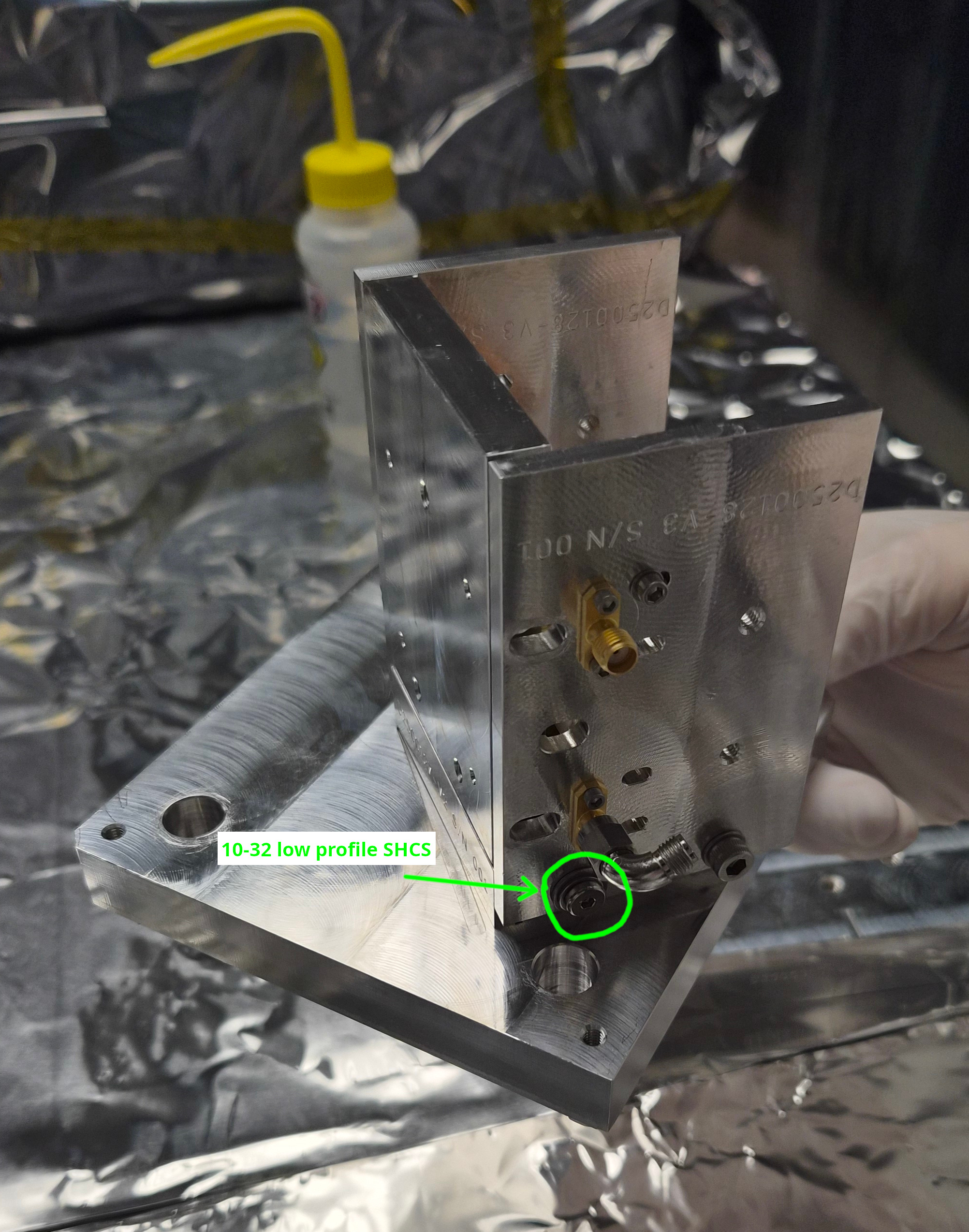
10-32x0.375" SHCS that was blocking the access to one 1/4-20 screw was replaced with a low profile 10-32 SHCS.
"Issue 2" in alog 88862 was solved.
See picture, Mitch found a 10-32x0.5" SHCS with a low profile head. 0.5" seemed to be OK in that it's not too long, but we used two washers to make sure that the scrwe doesn't bottom out.
EOM crystal mounting practice part 2 (with a remote help from Michael)
Summary:
Laxen method test.
In alog 88862 we left the EOM module with the alumina piece mounted using Laxen method (no gap between the input side plate and the front plate, a big gap for the output side).
Shining flashlight into the iput or output aperture in the side plates is useful to see the gap between the electrode plate and the alumina piece, and we found that there was indeed a small gap only on one side (i.e. the "crystal" was pinched at the edge).
I loosened the screws for the face plate and repeated the mounting procedure, but this time being extra careful to tighten the screws by tinier amount (than my previous attempts) at a time while applying a gentle pressure from the top. As soon as I got much tighter than finger-tight, I stopped. This resulted in what was seemingly a good contact between the alumina and the electrode, no light visible between them.
See nogap.jpg, this is a representative picture of GOOD contact (even though I cannot prove that the contact is really plane-to-plane not just plane-to-one edge of the crystal).
Another picture gap.jpg is an example of BAD contact. It's hard to see but there's no gap at either edges closer to input/output faces, the gap is only in the middle. I don't have a good explanation for this.
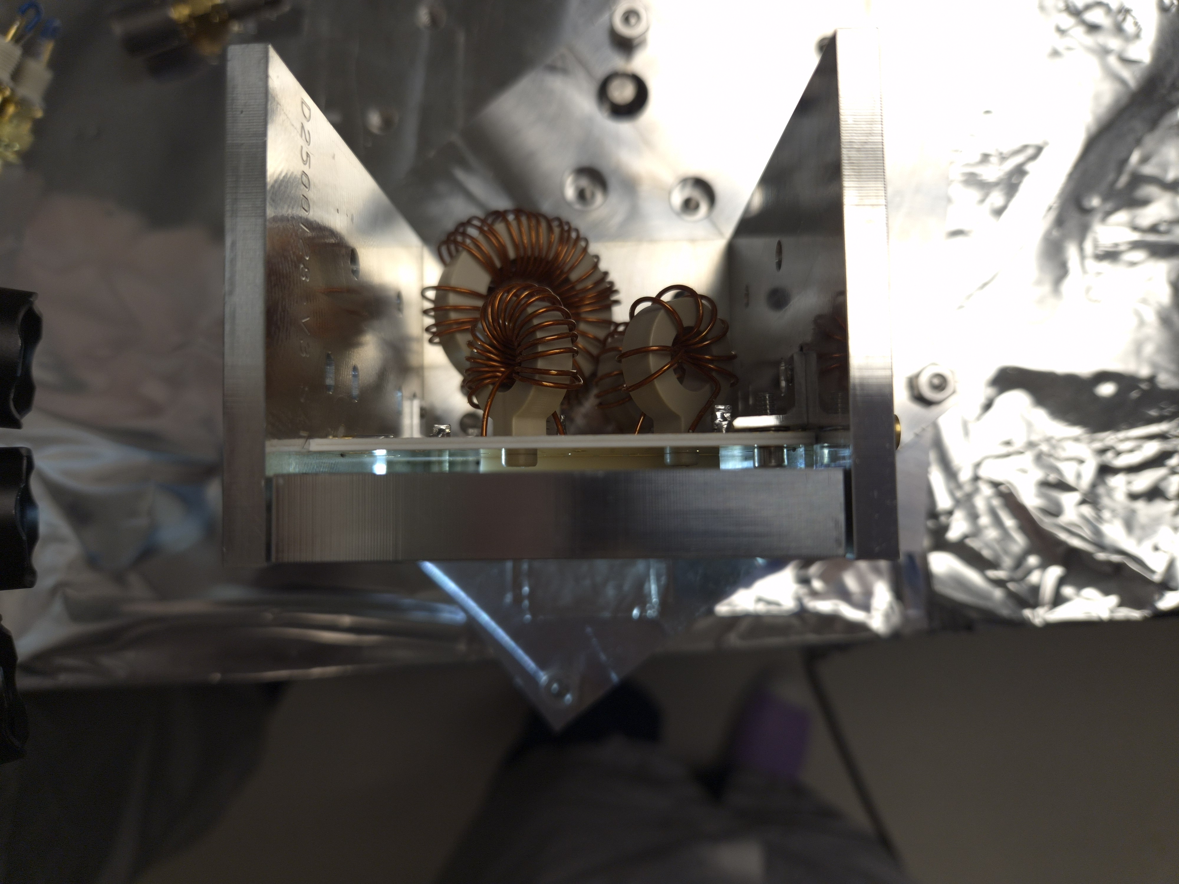
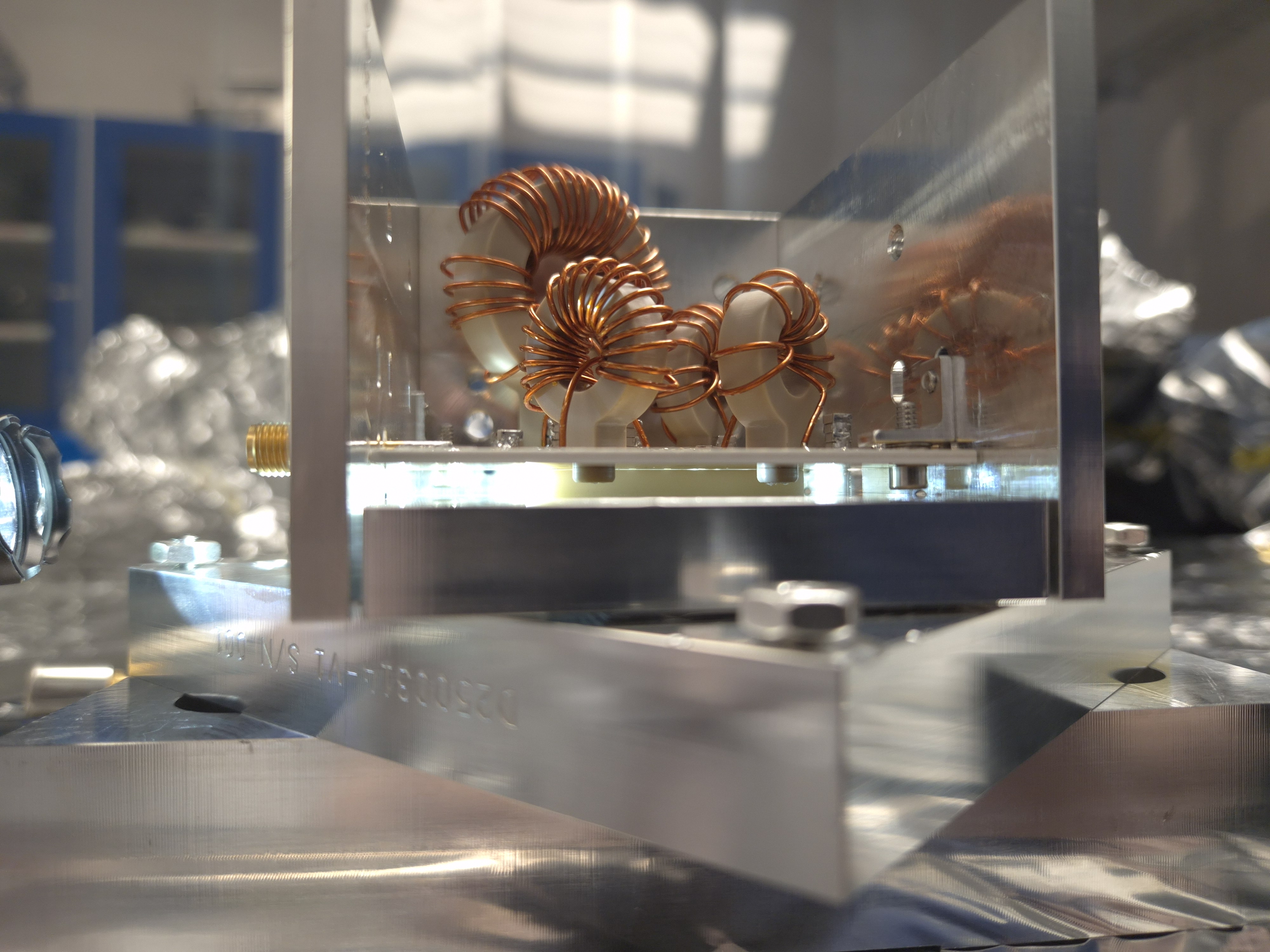
Appert method tests.
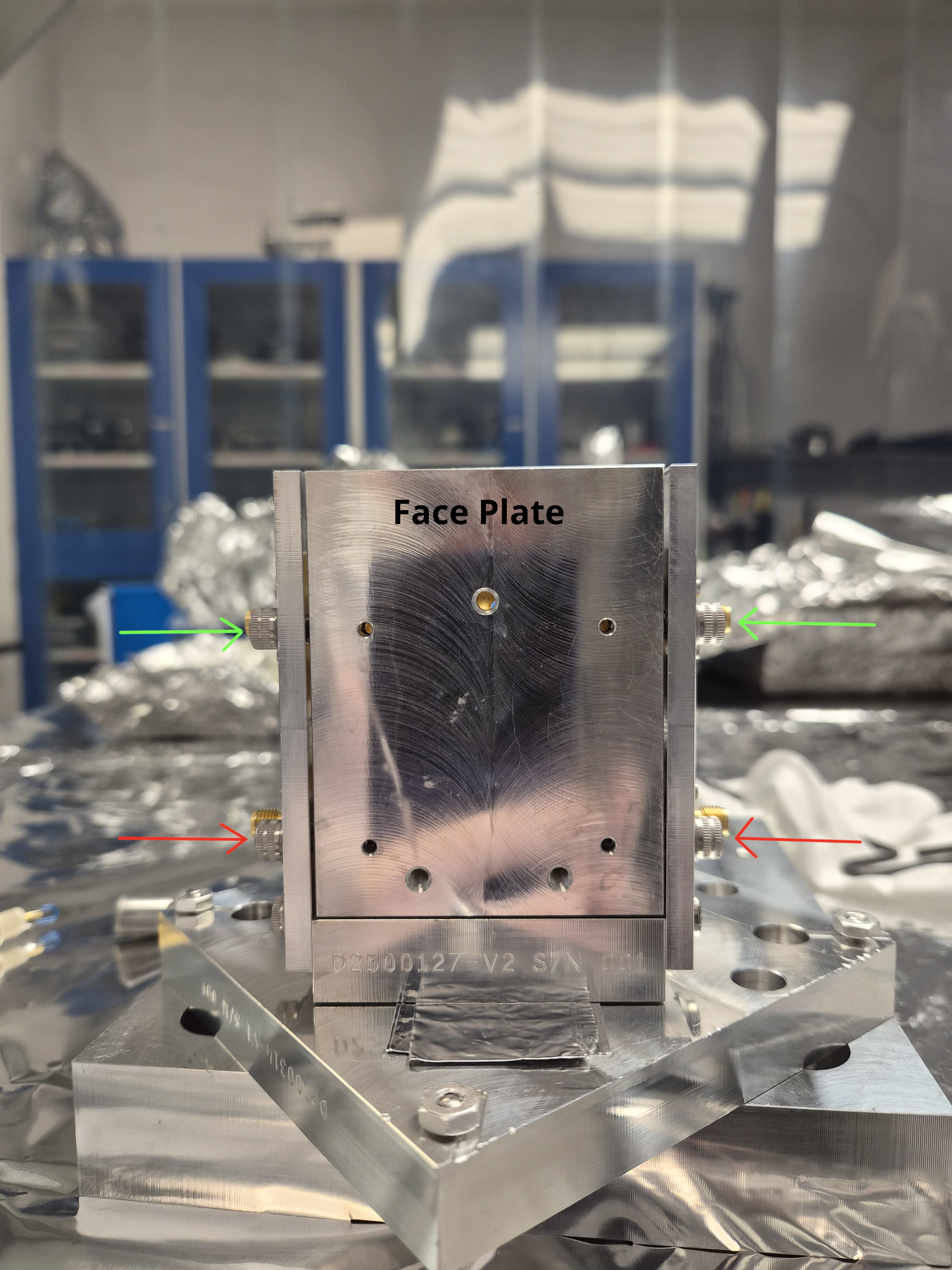
We also tested Stephen's suggestion to make a gap on both sides of the front plate. This was trickier but doable by using two Allen keys. The third attachment (EOMassembly.jpg) shows the EOM placed on top of the EOM mount parts just for picture AFTER the alumina was mounted. During the mounting process, the face plate is facing down, and two allen keys will tighten two screws with green (or red) arrows in the picture with tiniest rotation at a time. Green, red, green, red, repeat it until it feels reasonably tight but much, much looser than you'll usually do for tight mechanical connection. After this was done, neither Matt nor I were able to undo the screws by finger.
We did this twice, both times no gap between the alumina and the board, and alumina didn't slip out.
Output side plate might be warped?
In the assembly picture, can you see that the gap between the face plate and the output side panel (right on the picture) is uneven, but the gap for the input (left on the picture) is fairly even? I don't think this is an optical illusion. This might be related to the reason why the crystal ALWAYS slips out when the face plate is tightened down to the output side plate, see my alog (88862). Quoting myself, "no matter what we did, the alumina piece (i.e. fake RTP for excercize) slid out of the assembly but only after tightening the screws". Maybe it's the output side plate.
Reflection measurement.
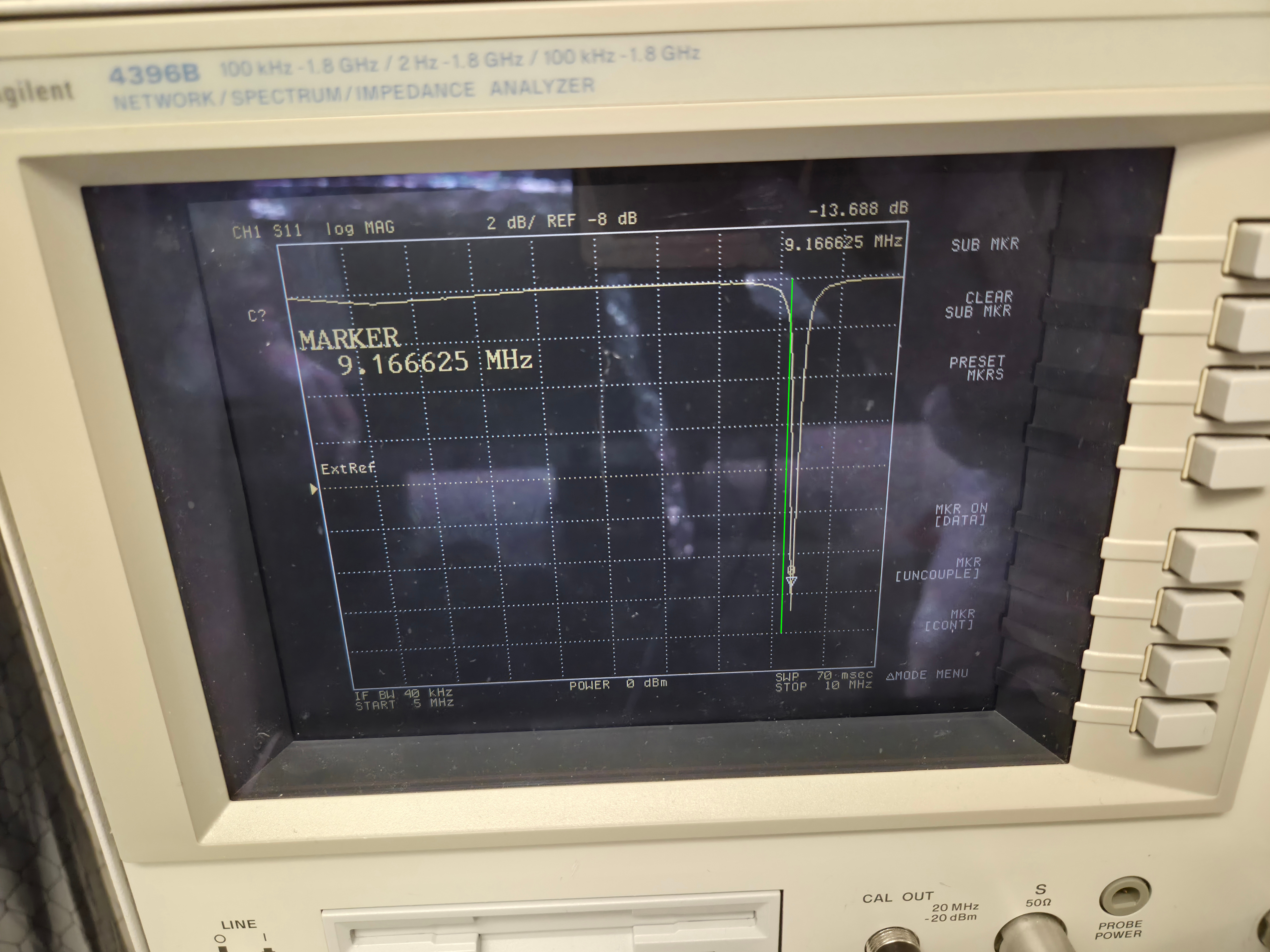
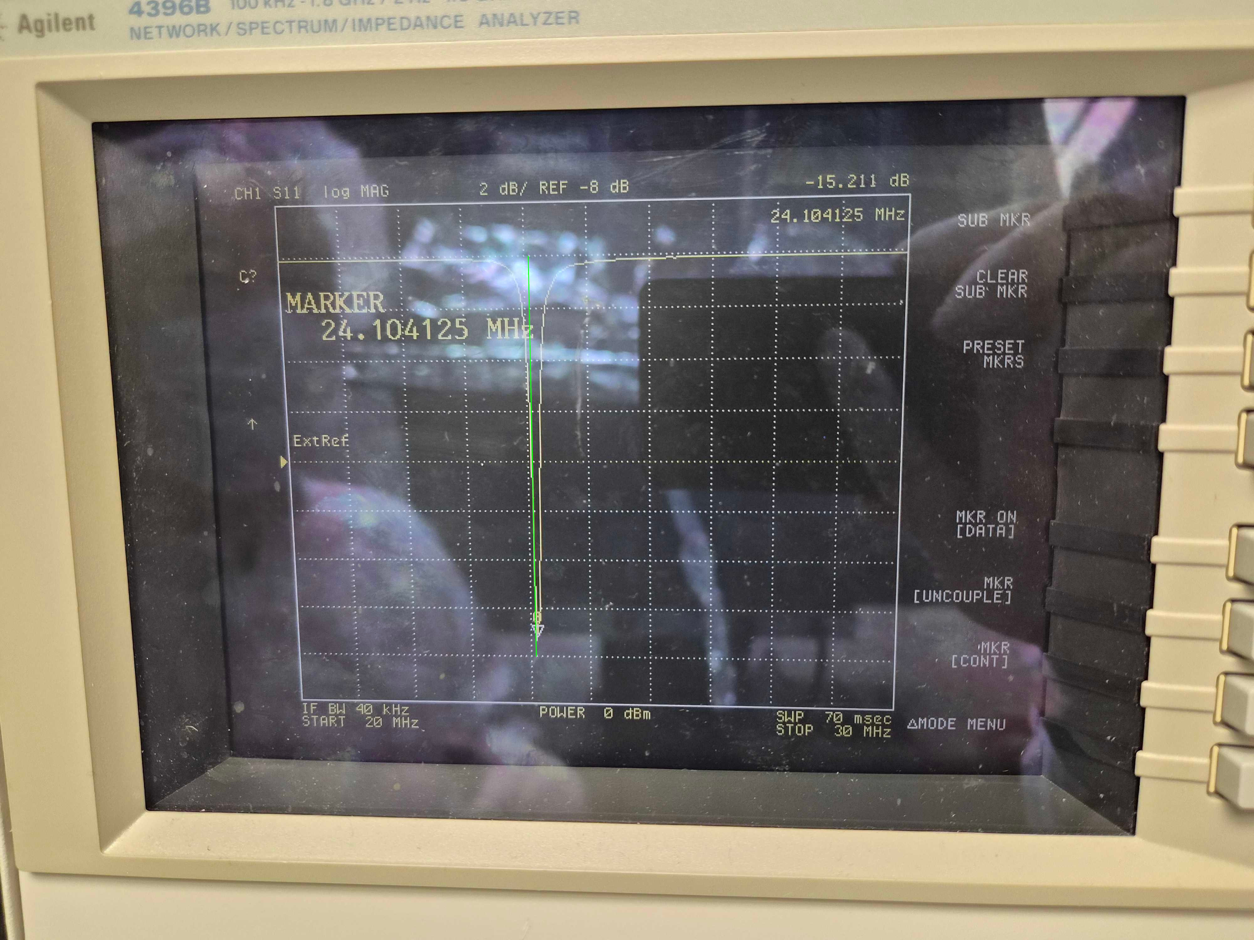
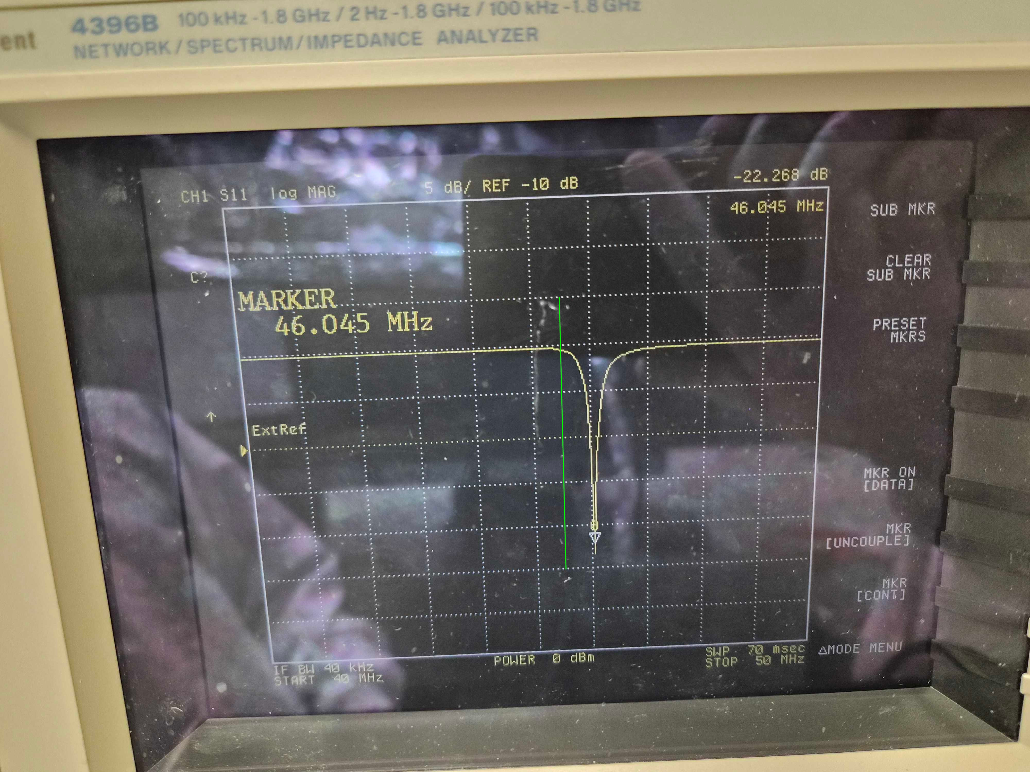
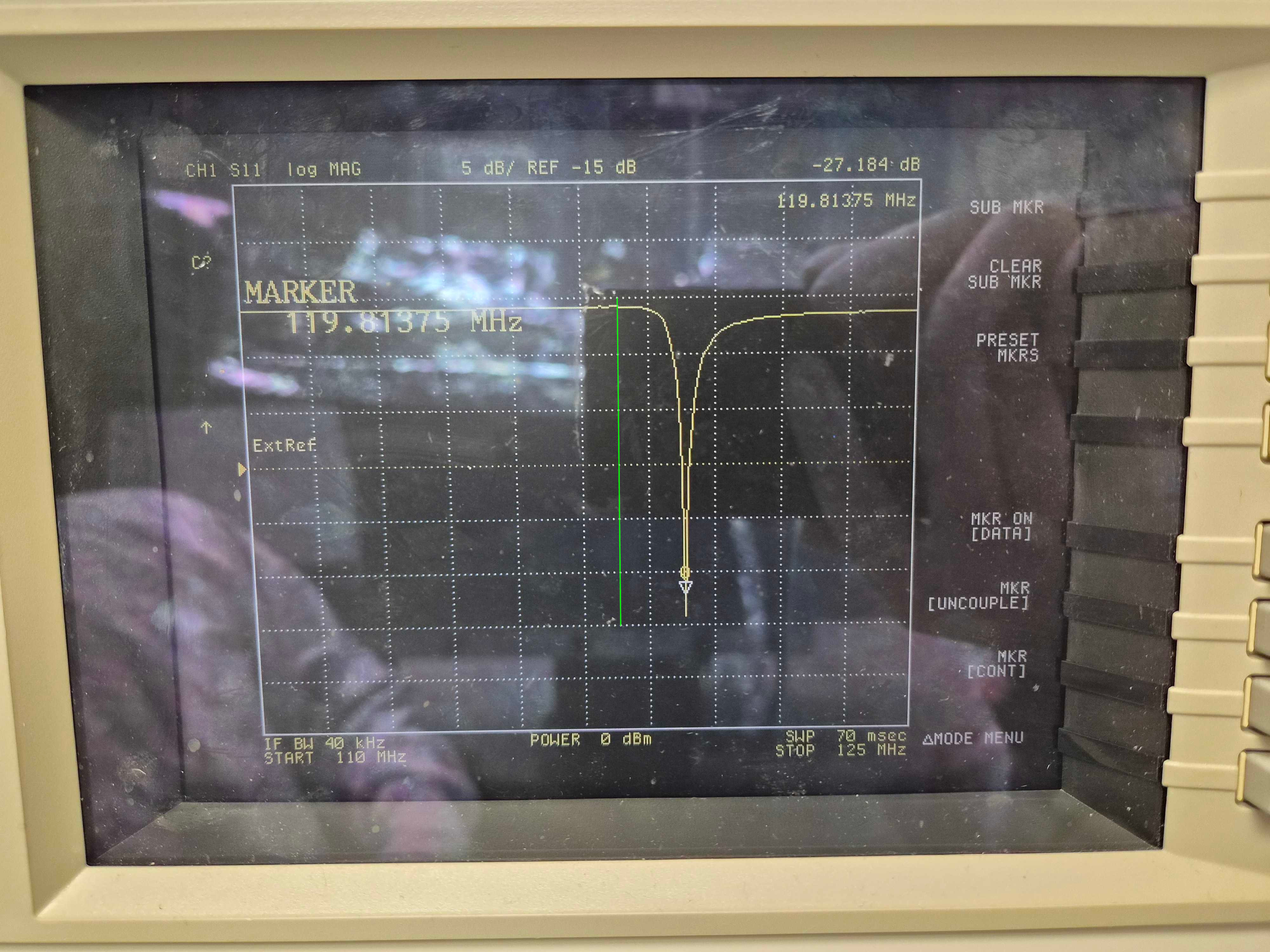
For each of the above three practices (one with Laxen method, two with Appert method), S11 coefficient was measured for all four ports.
What we found was that all four reflection dips were higher than they are supposed to be. According to Michael, alumina should give us similar results to RTP. I don't list results for all three sets (3x4=12 numbers) because numbers were pretty consistent across the sets, maybe give or take 10kHz or so.
| Nominal LHO/LLO (MHz) | 9.100230 / 9.099055 | 24.078360 / 24.078 | 45.50115 / 45.495275 | 118.30299/118.287715 |
| Measured (representative number) (MHz) | ~9.17 | ~24.10 | ~46.05 | ~119.8 |
In the attached pictures, green line is roughly where the center should be. 9.1 and 24.08 look reasonable to me. Not sure about 45.5MHz, it's 450kHz off. 118.3MHz is totally, totally off.
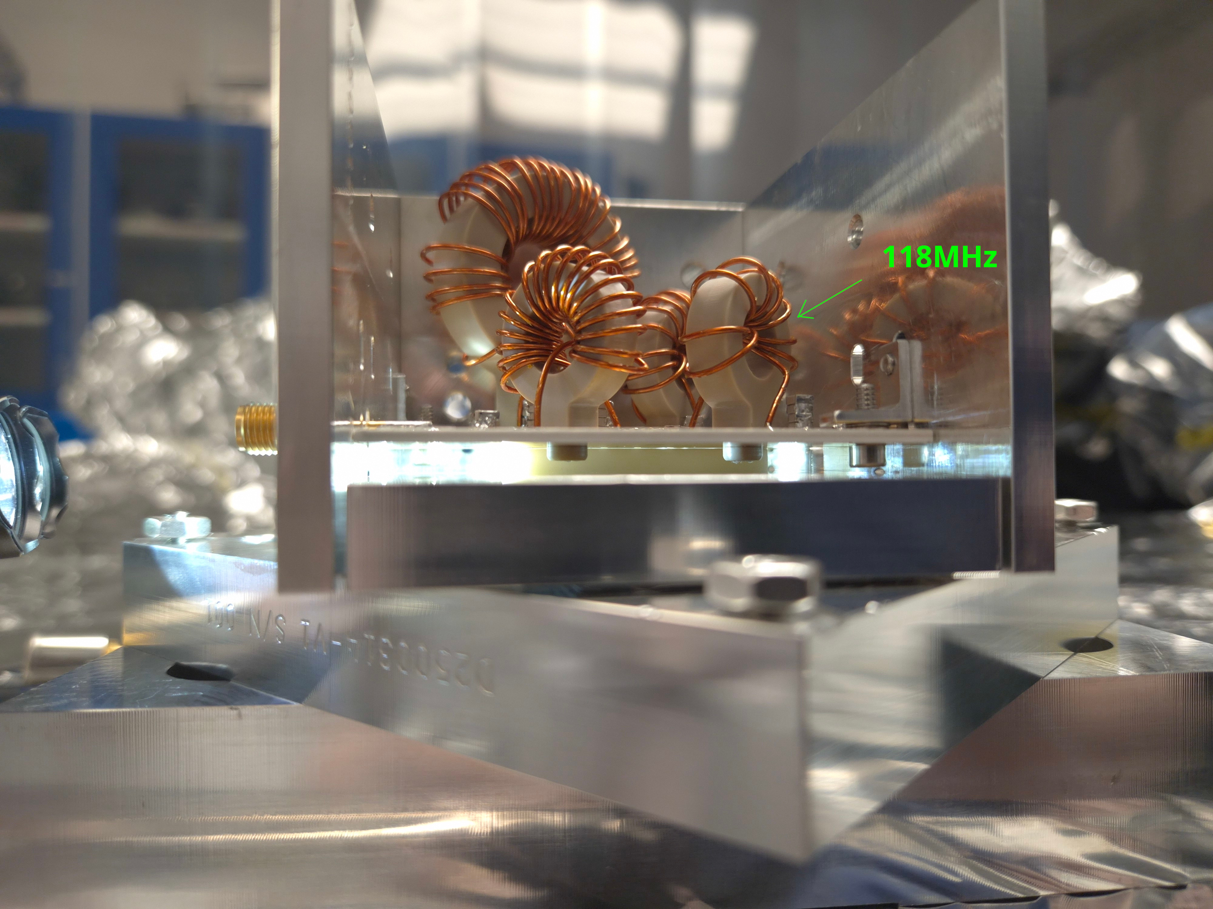
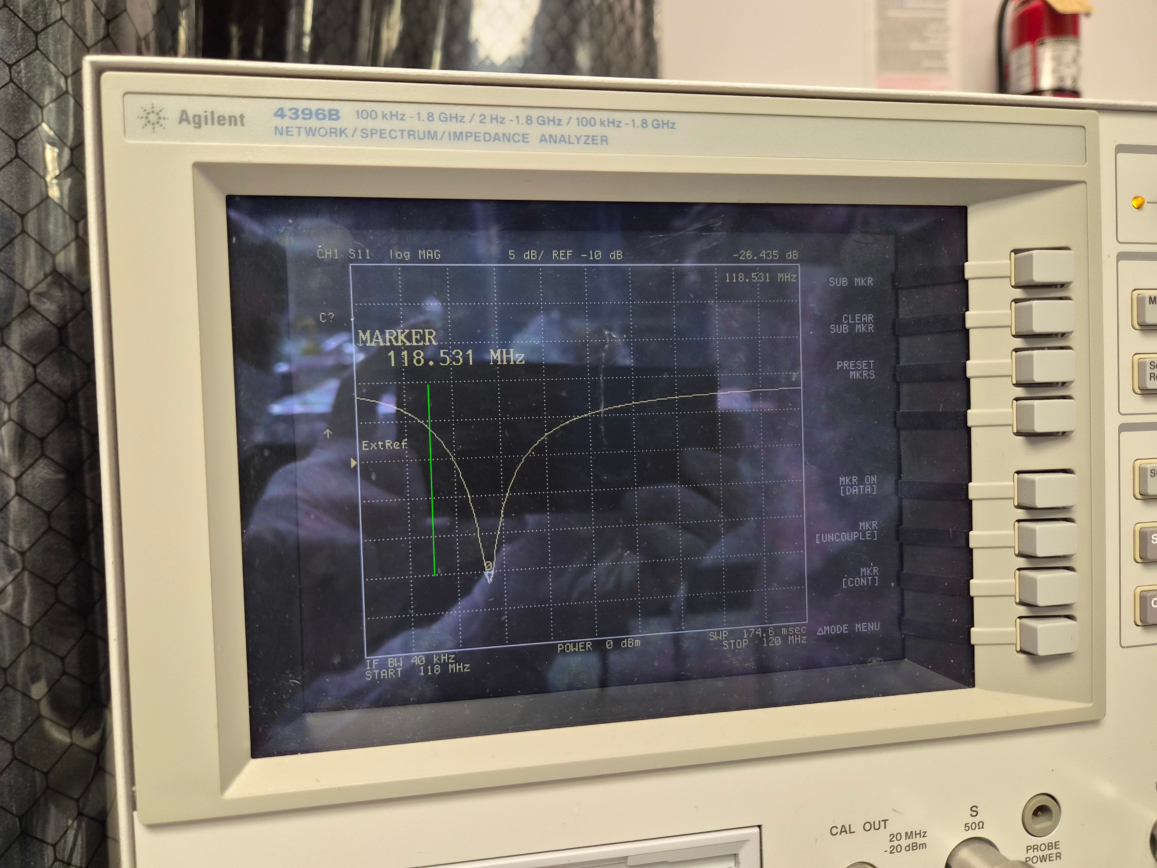
As I wrote in the summary, I tried bending the coil windings for the 118MHz (bendandsqueeze.jpg) because it was the worst but also because it was the one with the loosest of all four coils (118MHzWinding.jpg), and it had a huge effect. With just a few rounds of bending/squeezing I was able to go down to 118.53MHz (afterbending_118MHz.jpg). I could have passed 118.3 and gone to the other side easily but I stopped there.
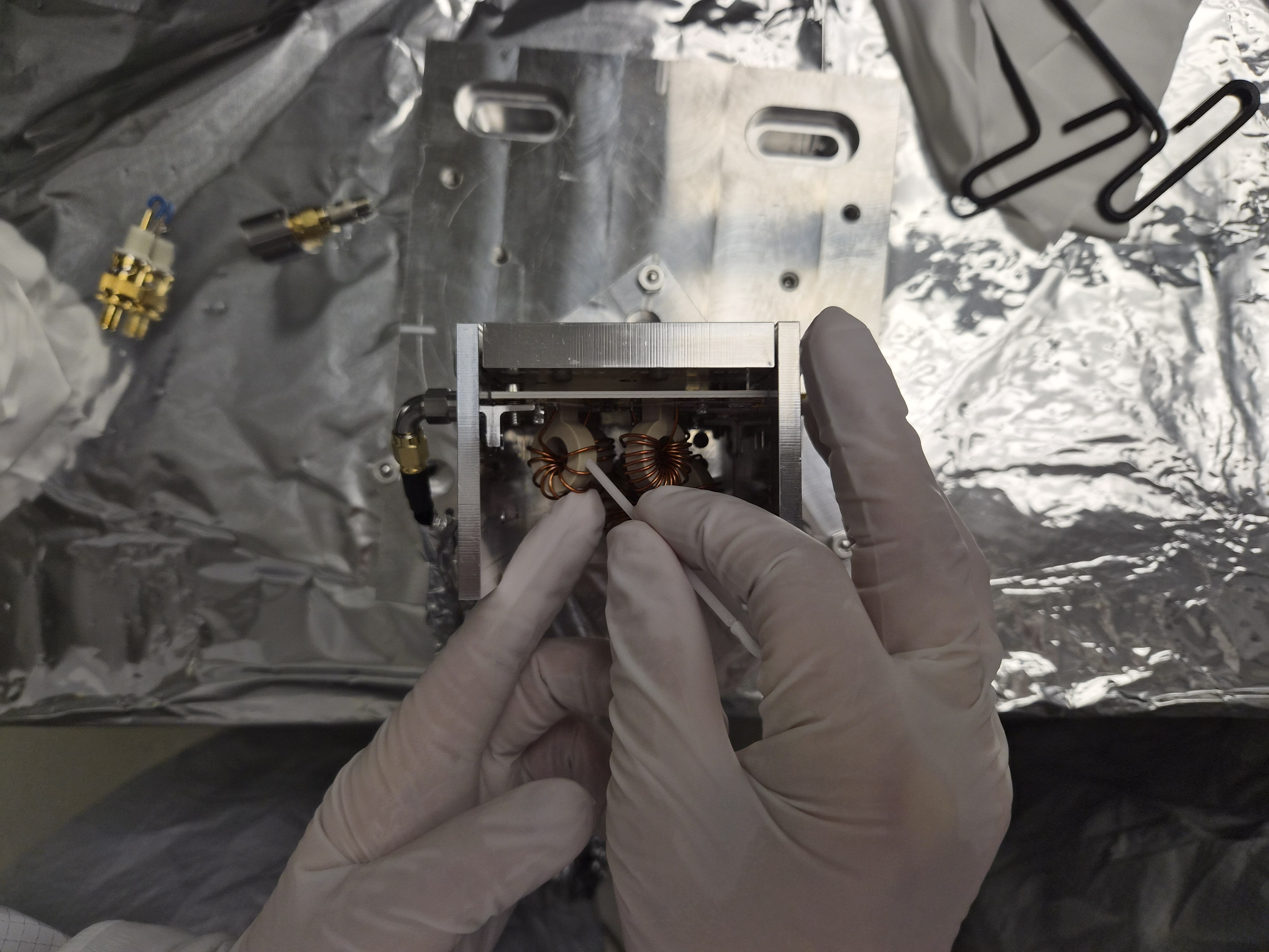
Just in case somebody else must do this, here's what I did to measure S11 (reflection coefficient).
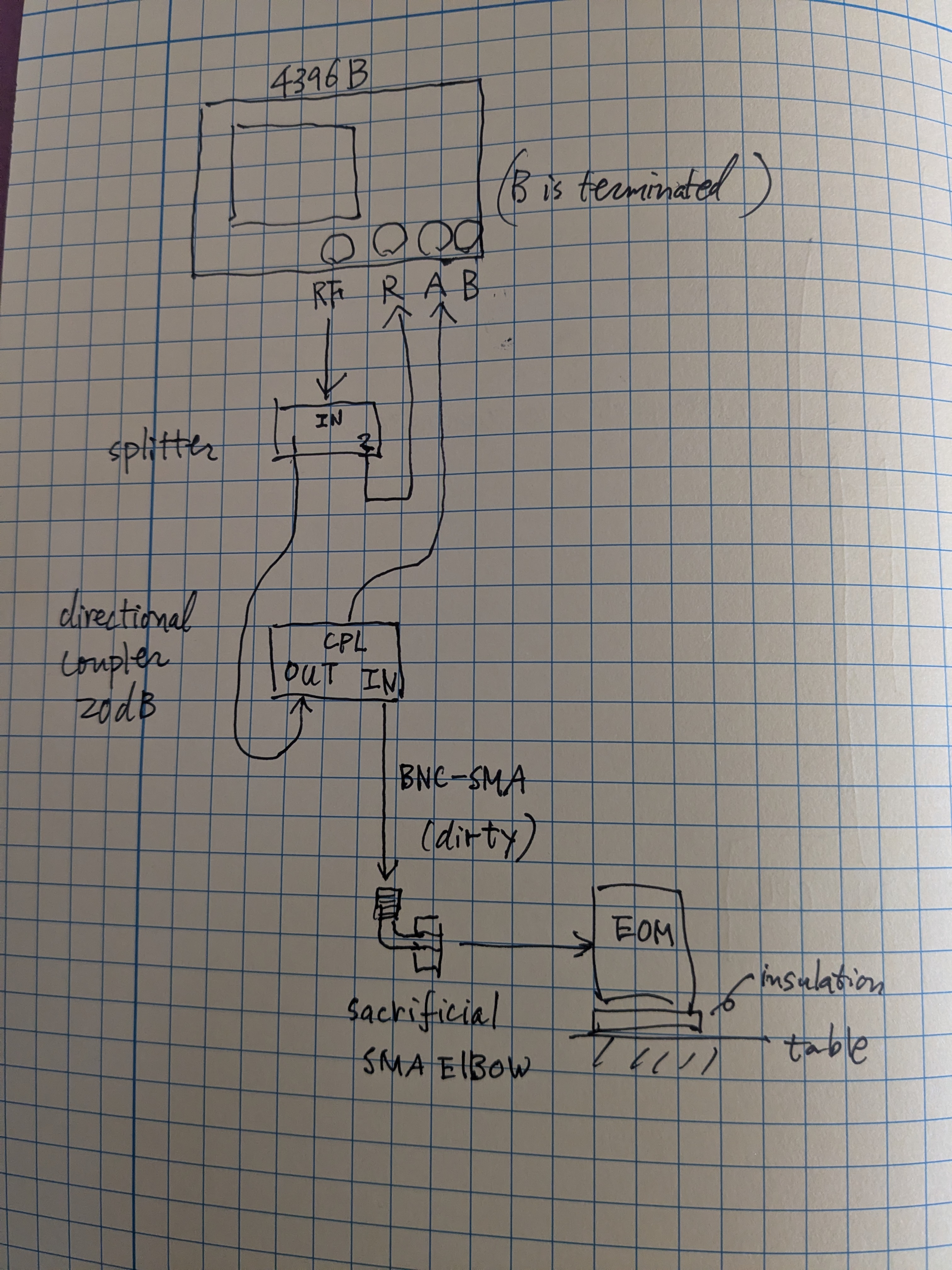
If you go to the optics lab, everything is already set up like in the attached cartoon except that the dirty cable is removed from the coupler and placed on top of the optics table. You might still do the calibration again (because we turned off the analyzer at the end of the day and I cannot remember if the calibration results are kept in the analyzer). Remember that EOM is class A but your cables are dirty (even though we wiped the connectors of the dirty cable using q-tips and IPA). We're using one sacrificial SMA elbow that used to be class A to connect your dirty cable to the EOM.
Anyway, calibration. Set the frequency range to whatever you want but make sure that it covers the frequency range of main interest, like at least 9MHz to 125MHz or so while performing S11 calibration.
Connect the BNC of the dirty cable to the INPUT connector of the directional coupler, like in the attached cartoon.
Press "cal" button and select S11 calibration. Don't connect anything to the SMA of the dirty cable and press "Open" button. Next attach a hand-made short circuit plug to the dirty cable via BNC male to SMA female connector. Press "Short". Then connect a 50Ohm SMA terminator to the dirty cable via SMA barrel. Press "Load". Then press "Done".
Now you're done with calibration. Press "Measure" and make sure that you're measuring S11.
Clean the SMA with IPA and q-tip again. Connect the dirty cable to the elbow, and the elbow to the EOM. Set the frequency range to whatever you want. That's it.
Quick Monday update.
I measured S11 coeff without the crystal/alumina but with the front panel.
Reflection dips with/without alumina are:
| ~9.17/9.192 | ~24.10/24.214 | ~46.05/47.106 | ~118.53/122.736 |
So the frequencies are consistently higher without the crystal/alumina.
EPO tagged
J. Kissel, O. Patane, D. Barker, F. Clara, M. Pirello
Our big SUSB123 and SUSH34 to SUSB13 and SUSB2H34 upgrade last week wasn't the full upgrade for O5.
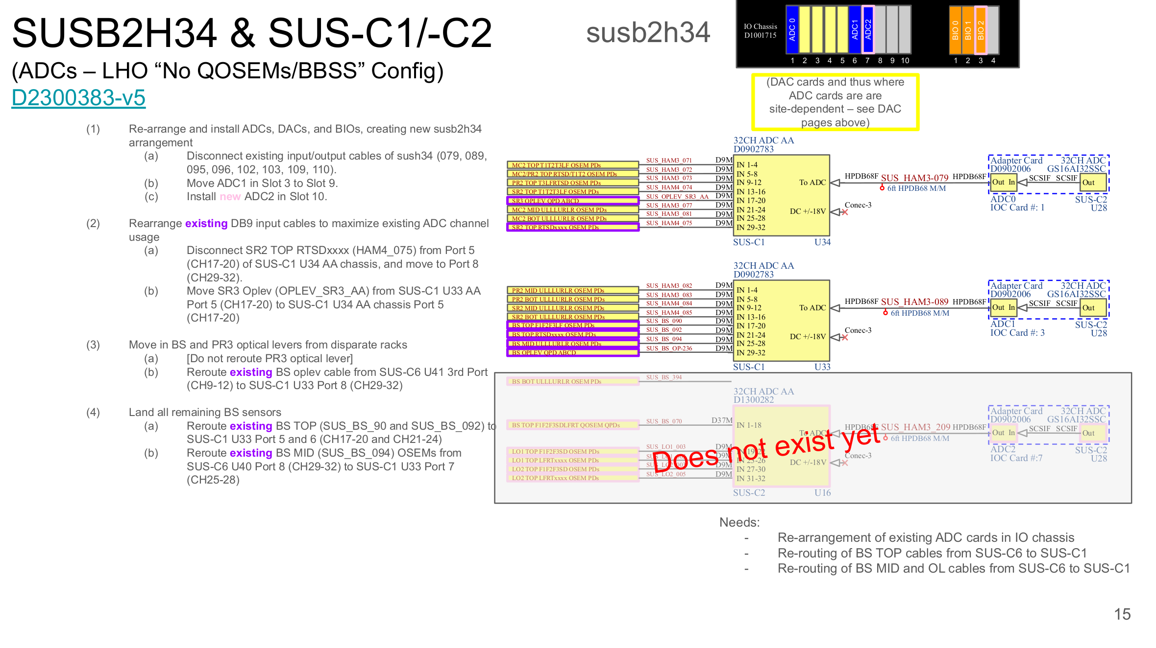
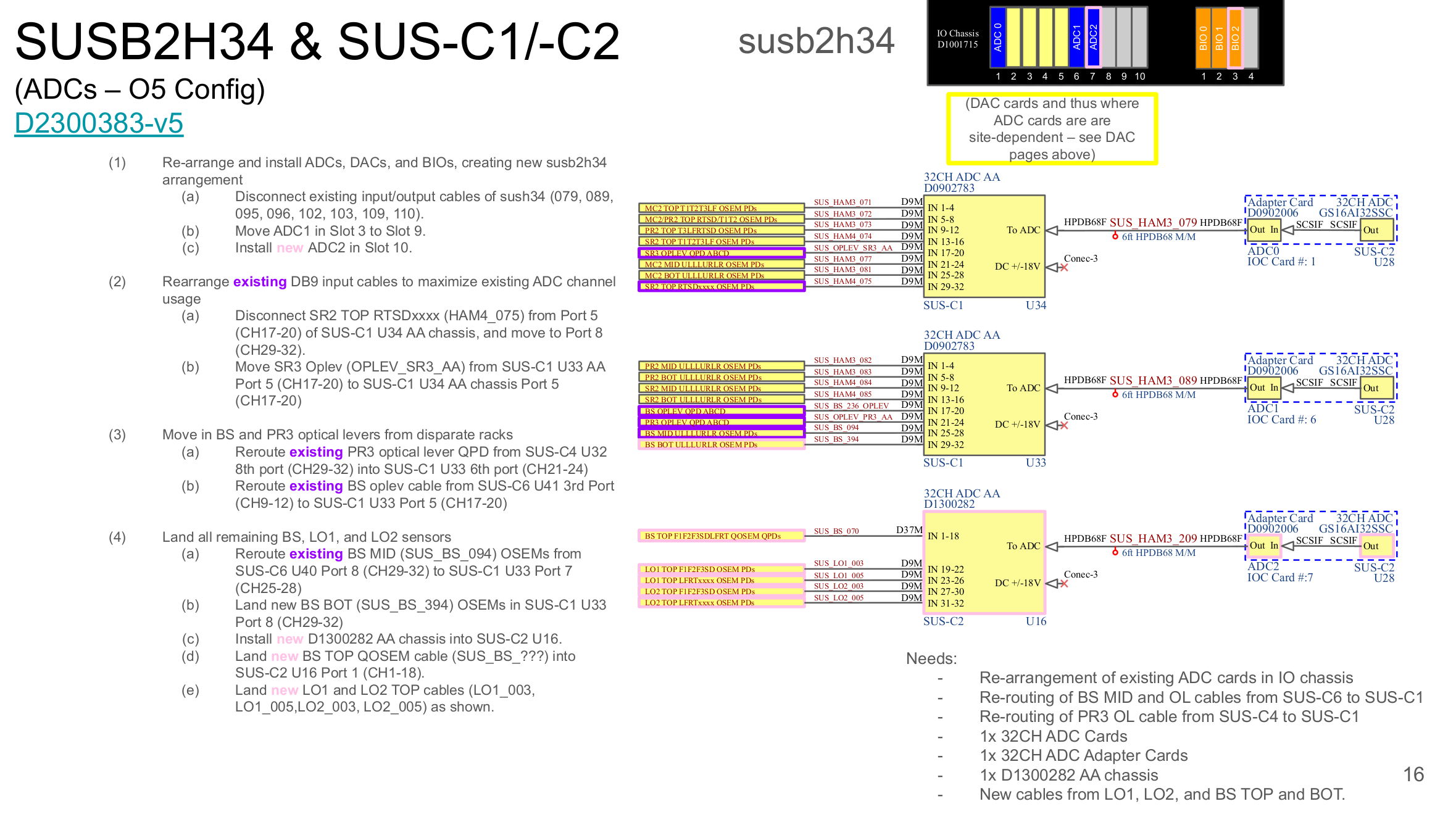
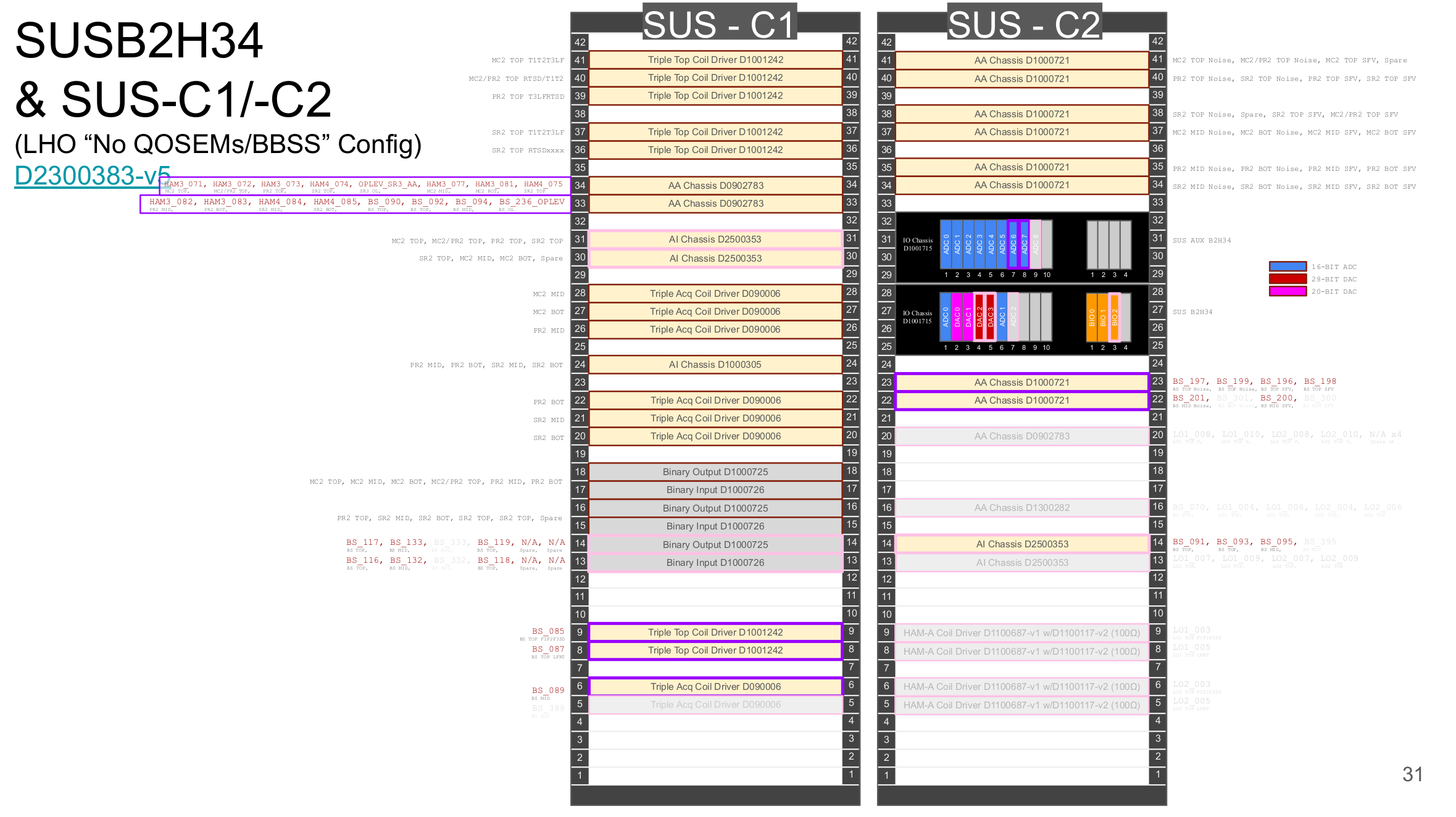
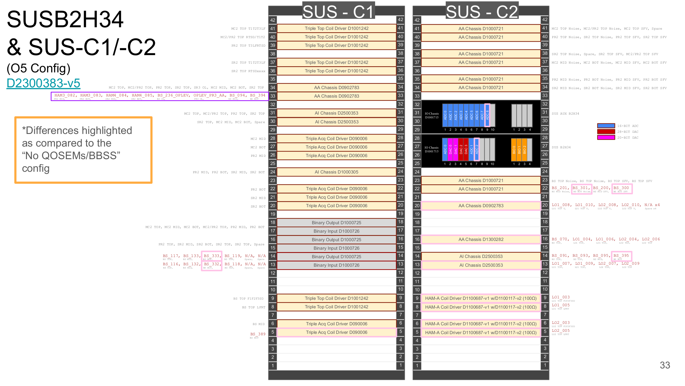
SUSB13 is fully upgraded to its O5 configuration, but for SUSB2H34, we can't fully upgrade to the final O5 build yet because we still need full control of the BSFM for the February commissioning period, whereas O5 will have the BSFM replaced with the BBSS (with QOSEMs instead of BOSEMs), requiring different electronics. The final O5 build will also include the electronics for the new suspensions LO1 and LO2. Going from the current configuration, which we call the "No QOSEMs/BBSS" configuration, to our final O5 build will require eight new chassis and two new ADC cards.
Since we will be needing to add/change things on the racks, that future upgrade will also come with user model additions/changes.
Table showing comparison diagrams
| Current “No QOSEMs/BBSS” Config | Final O5 Config | |
| Rack overviews | slide31 | slide33 |
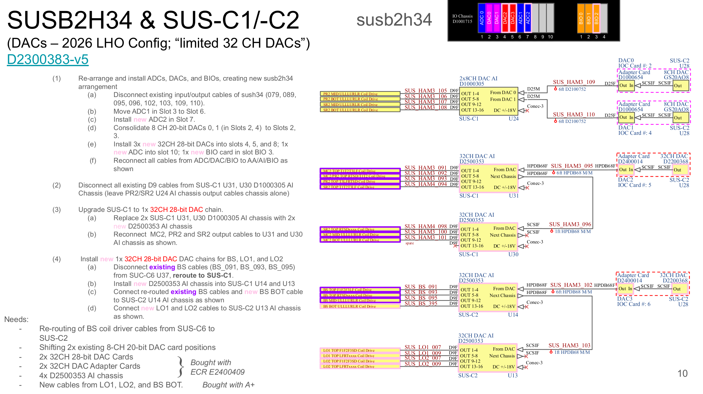
| DACs | slide10 (excluding BS BOT/LO1/LO2 and AI in U13) | slide10 (everything) |
| ADCs | slide15 | slide16 |
| BIOs | slide21 (excluding BS BOT chans) | slide21 (everything) |
| AUX ADCs | slide26 (excluding pink) | slide26 (everything) |
I've also attached the slides above in pdf form here. The full slides outlining all the changes O4 -> now -> O5 can be found here.
Changes needed to go from current configuration to final O5 configuration:
SUS-C1
U33:: Remove cable inputs for (BSFM) BS M1 OSEM sensors, re-arrange cable inputs for BS M3 Oplev to make room for (BBSS) BS M3 OSEM sensors, and bring in PR3 M3 Oplev because we can
U14:: Add (BBSS) BS M3 input for Binary Output
U13:: Add (BBSS) BS M3 input for Binary Input
U5 :: New D090006 TACQ Driver for (BBSS) BS M3
SUS-C2
U22:: Add (BBSS) BS M3 Noisemon and (BBSS) BS M3 SFVmon inputs
U20:: New D0902783 AA Chassis for LO1 M1 and LO2 M1 HAM-A Coil Driver Volt Monitors
U16:: New D1300282 AA Chassis for (BBSS) BS M1 QOSEM sensors and LO1 M1 and LO2 M1 OSEM sensors
U14:: Add (BBSS) BS M3 input to AI chassis
U13:: New D2500353 AI Chassis for LO1 and LO2 Coil Actuation
U9 :: New D1100687-v1 (100 Ohm Output Impedance) HAMA Coil Driver for LO1 M1 F1F2F3SD
U8 :: New D1100687-v1 (100 Ohm Output Impedance) HAMA Coil Driver for LO1 M1 LFRTxxxx
U6 :: New D1100687-v1 (100 Ohm Output Impedance) HAMA Coil Driver for LO2 M1 F1F2F3SD
U5 :: New D1100687-v1 (100 Ohm Output Impedance) HAMA Coil Driver for LO1 M1 LFRTxxxx
susb2h34 IO Chassis
Needs an additional ADC Card (and adapter card and internal SCSI cable)
susauxb2h34 IO Chassis
Needs an additional ADC Card (and adapter card and internal SCSI Cable)


To clarify a bit on the status of SUSB13 and SUSB2H34, "as of these Jan 2026 changes, the SUSB13 racks and IO chassis are 'fully upgraded,’ as only the ITM QUADs are left in this system and there are no changes to the QUAD control system electronics for O5, and we’ve now upgraded the whole chassis to use 28-bit 32CH LIGO DACs. For the SUSB2H34 racks and IO chassis, while we’ve imported the existing BSFM beam splitter control system electronics, that’s all we can do at this point and we need the BS under control as it was for the Feb 2026 commissioning period. After that’s done, and as the suspensions get installed, we’ll add electronics to upgrade the BSFM BS to become a BBSS BS (with M1 QOSEMs replacing the M1 BOSEMs, and new M3 OSEMs for sensing and control there), and we install the LO1 and LO2 HRTS electronics for BHD as needed. So, it may be a while before the wiring diagrams match reality again".
(Thanks to Jeff for the clearer wording!)
