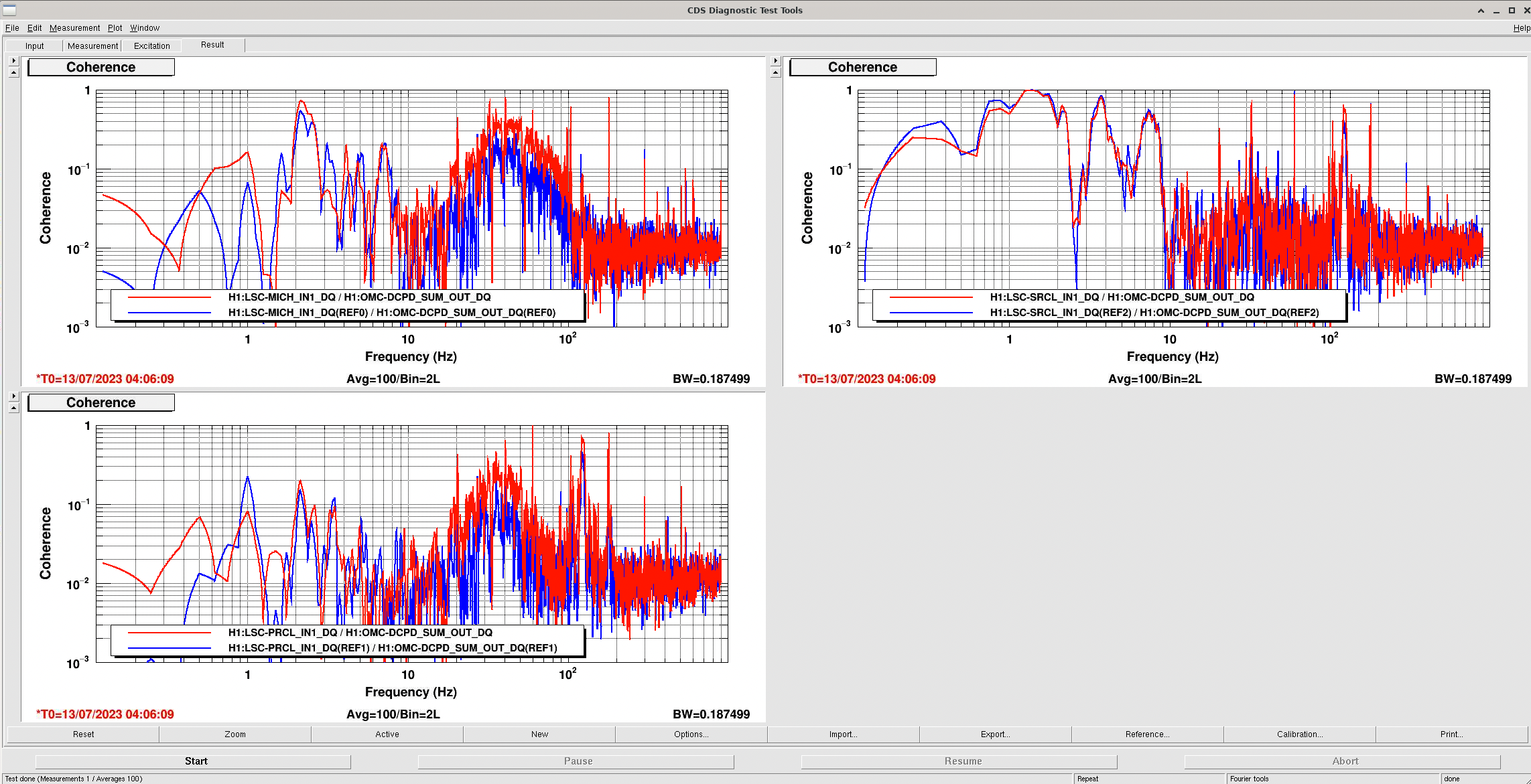
Gabriele and I think we have found the problem causing the large 102 Hz line. Today I plotted the LSC control and error signals, the LSC FF out signals and the OMC DCPD sum.
The 102 Hz line is clearly evident in SRCLFF out and OMC DCPD sum, but not present in the LSC control or error signals, or in MICHFF out.
The line showed up on August 4 when the SRCL feedforward was retuned. We have made no changes to the SRCL FF since.
Looking at the actual SRCL ff filter, there is an incredibly high Q (therefore narrow and hard to see without fine resolution) feature in the SRCL FF filter at precisely 102.1 Hz. Gabriele will post more details in a comment.
In short, we think this is the problem, and are taking the steps to fix it.
Edit to add:
How can we avoid this problem in the future? This feature is likely an artifact of running the injection to measure the feedforward with the calibration lines on, so a spurious feature right at the calibration line appeared in the fit. Since it is so narrow, it required incredibly fine resolution to see it in the plot. For example, Gabriele and I had to bode plot in foton from 100 to 105 Hz with 10000 points to see the feature. However, this feature is incredibly evident just by inspecting the zpk of the filter, especially if you use the "mag/Q" of foton and look for the poles and zeros with a Q of 3e5 (!!). If we ensure to both run the feedforward injection with cal lines off and/or do a better job of checking our work after we produce a fit, we can avoid this problem.
We did make sure to check the MICH feedforward in case the same error had occurred, but luckily everything looks fine there!

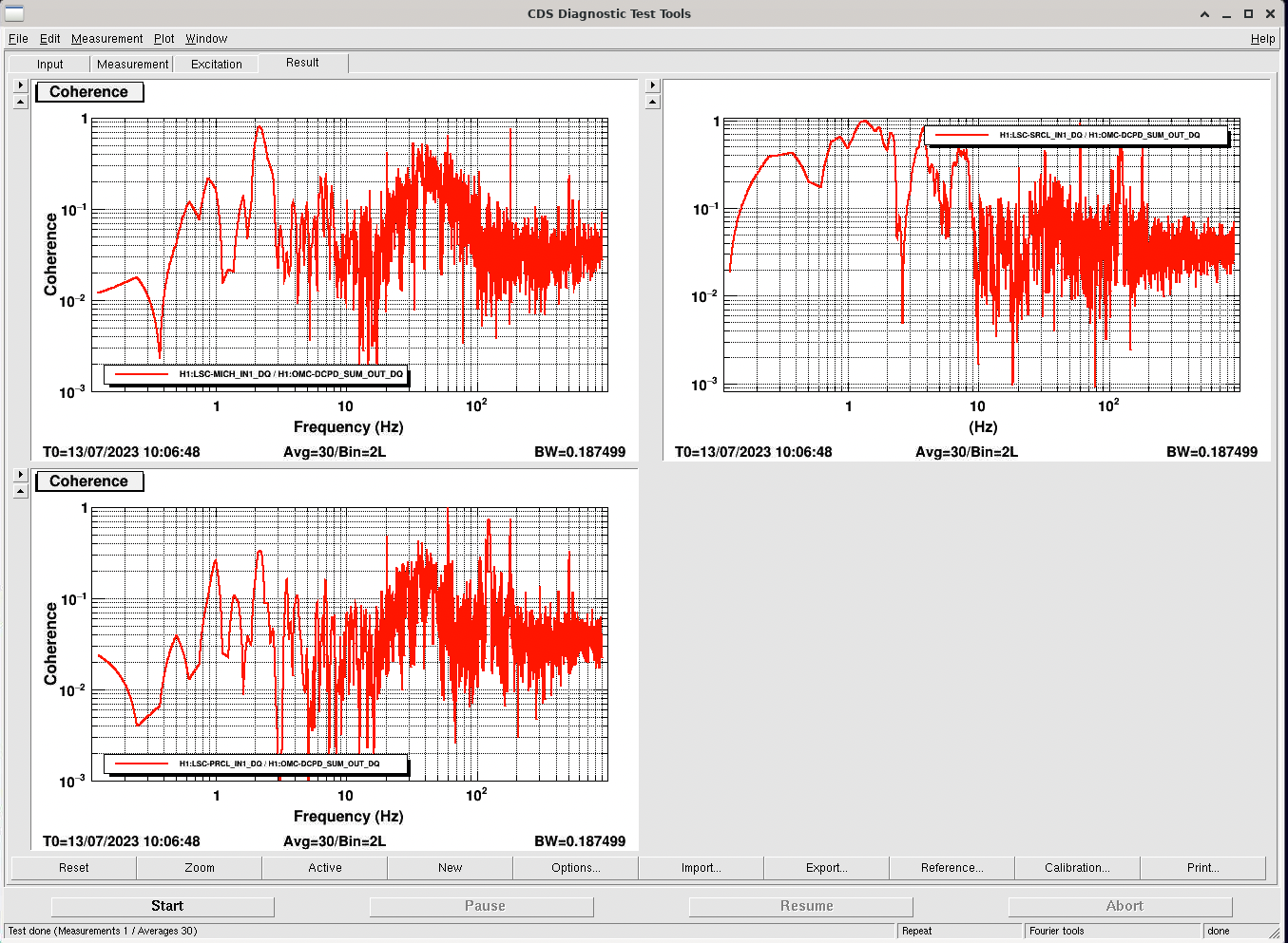
We removed the high Q zero/pole pair, saved and reloaded the filter.

We have relocked with no sign of the 102 Hz peak. Great! Tagging DetChar since they pointed out this problem first and Cal since they made adjustments to calibration lines to avoid this problem (and may want to undo those changes).