jeffrey.kissel@LIGO.ORG - posted 15:47, Friday 23 January 2026 - last comment - 15:57, Friday 23 January 2026(88872)
OPOS (VIP, VOPO, OPO) Suspension Open Light Current Compensating OFFSETs and GAINs Restored -- Lost Since 2021 and the Move from HAM6 to HAM7
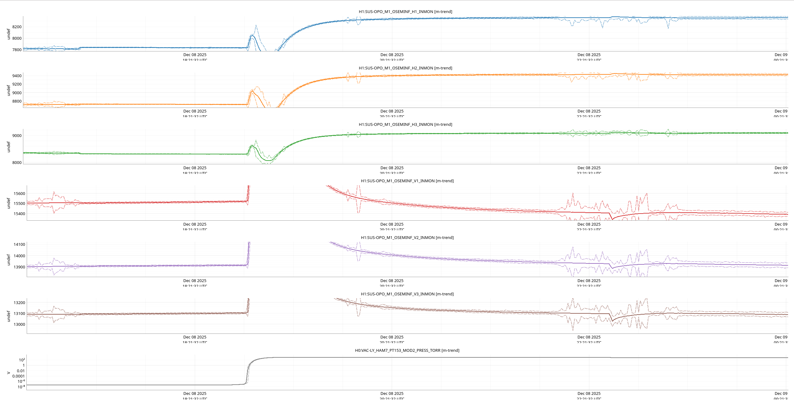
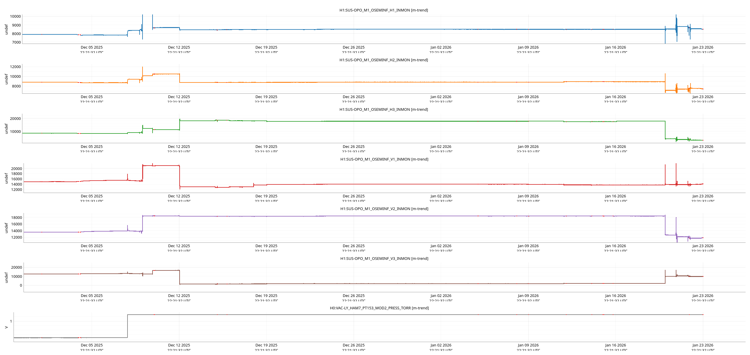
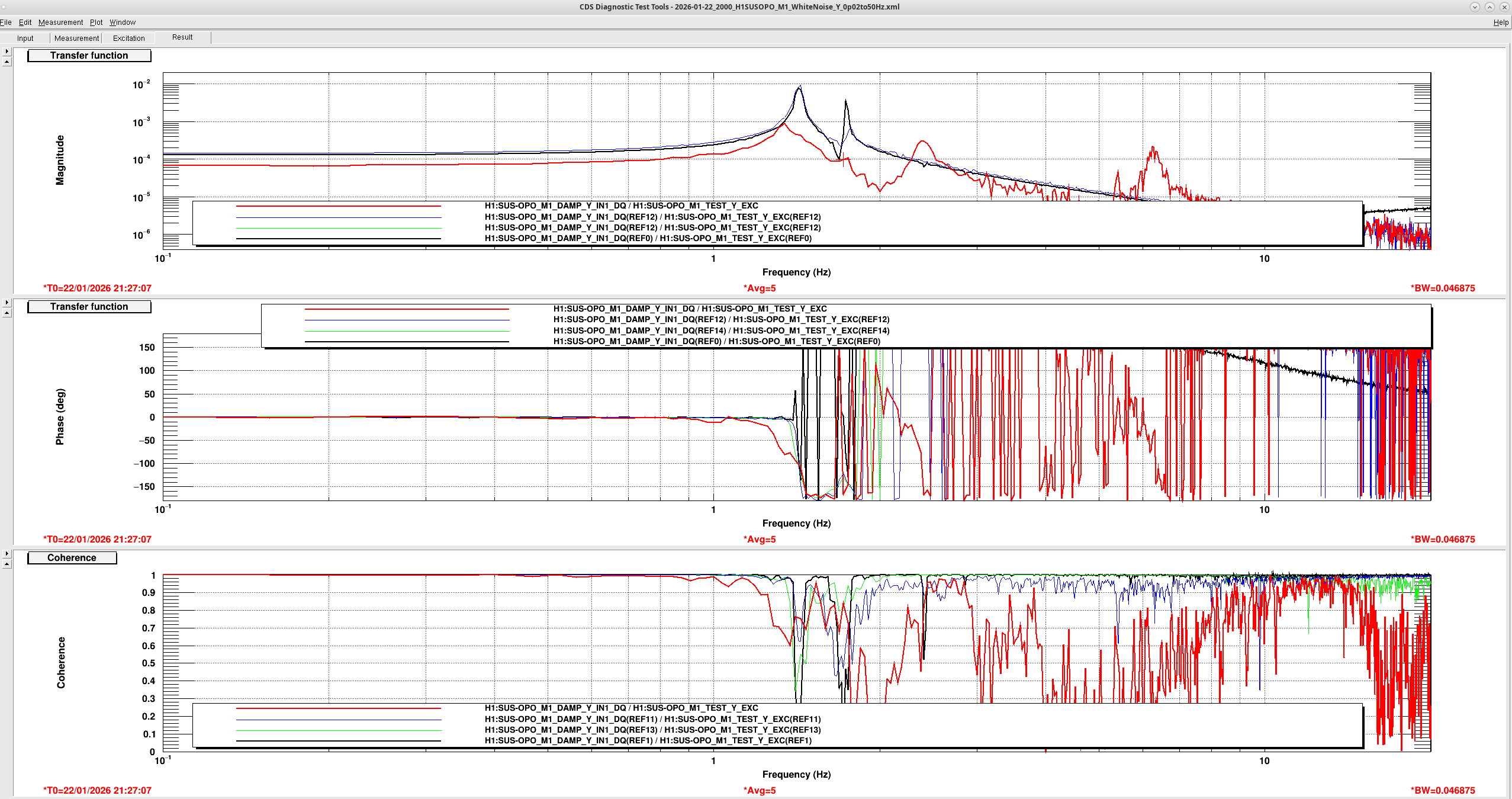
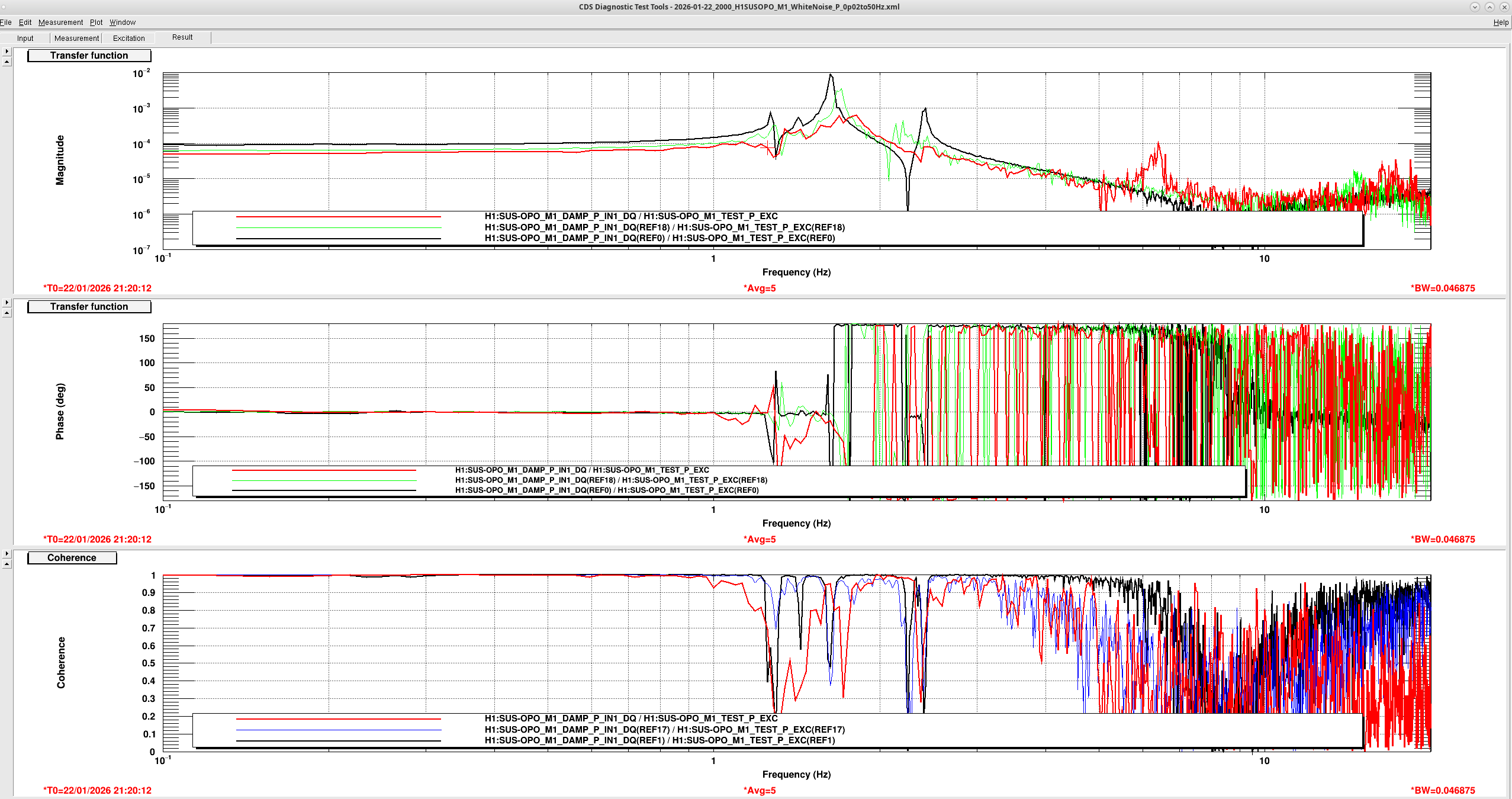
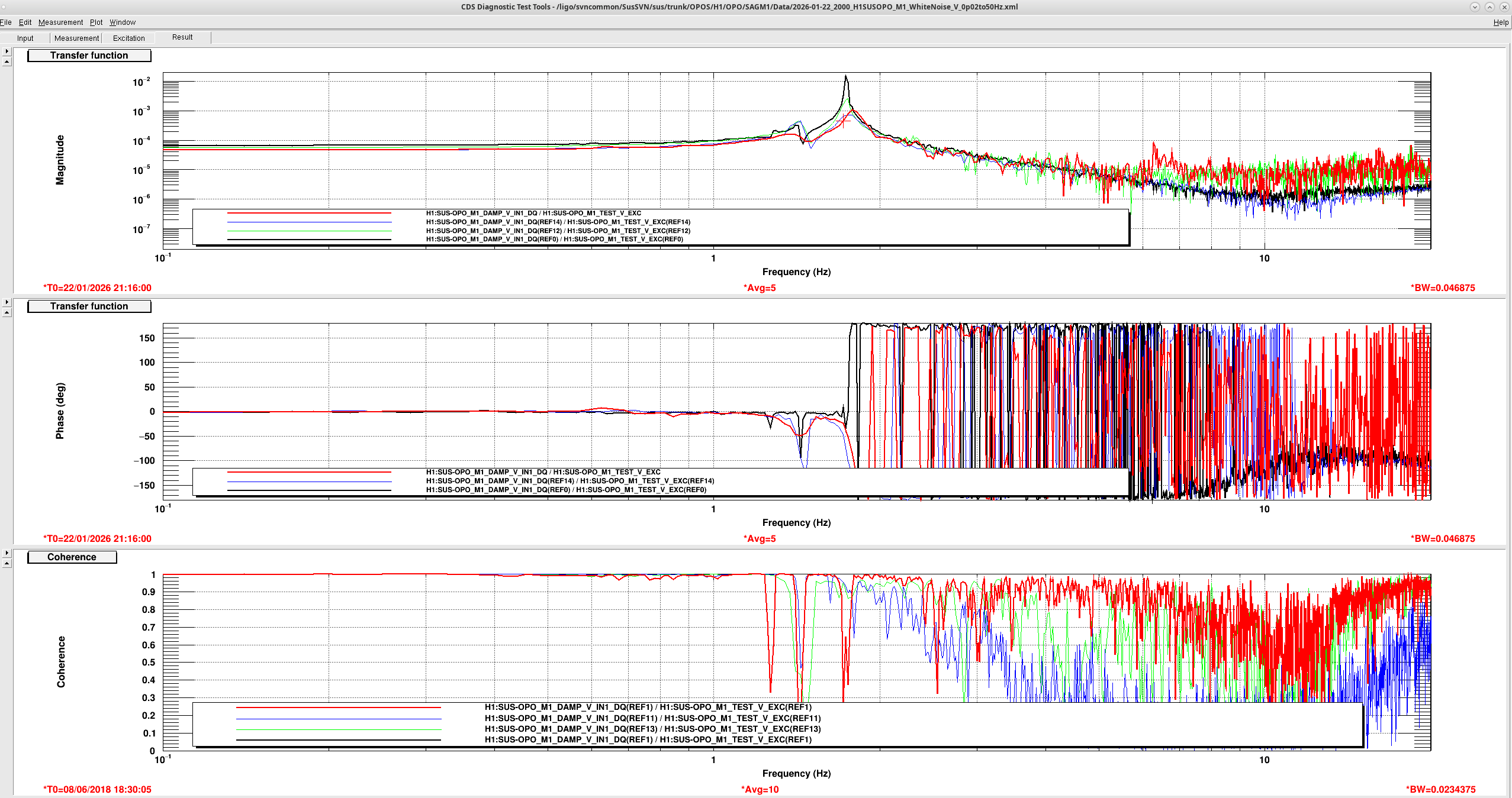
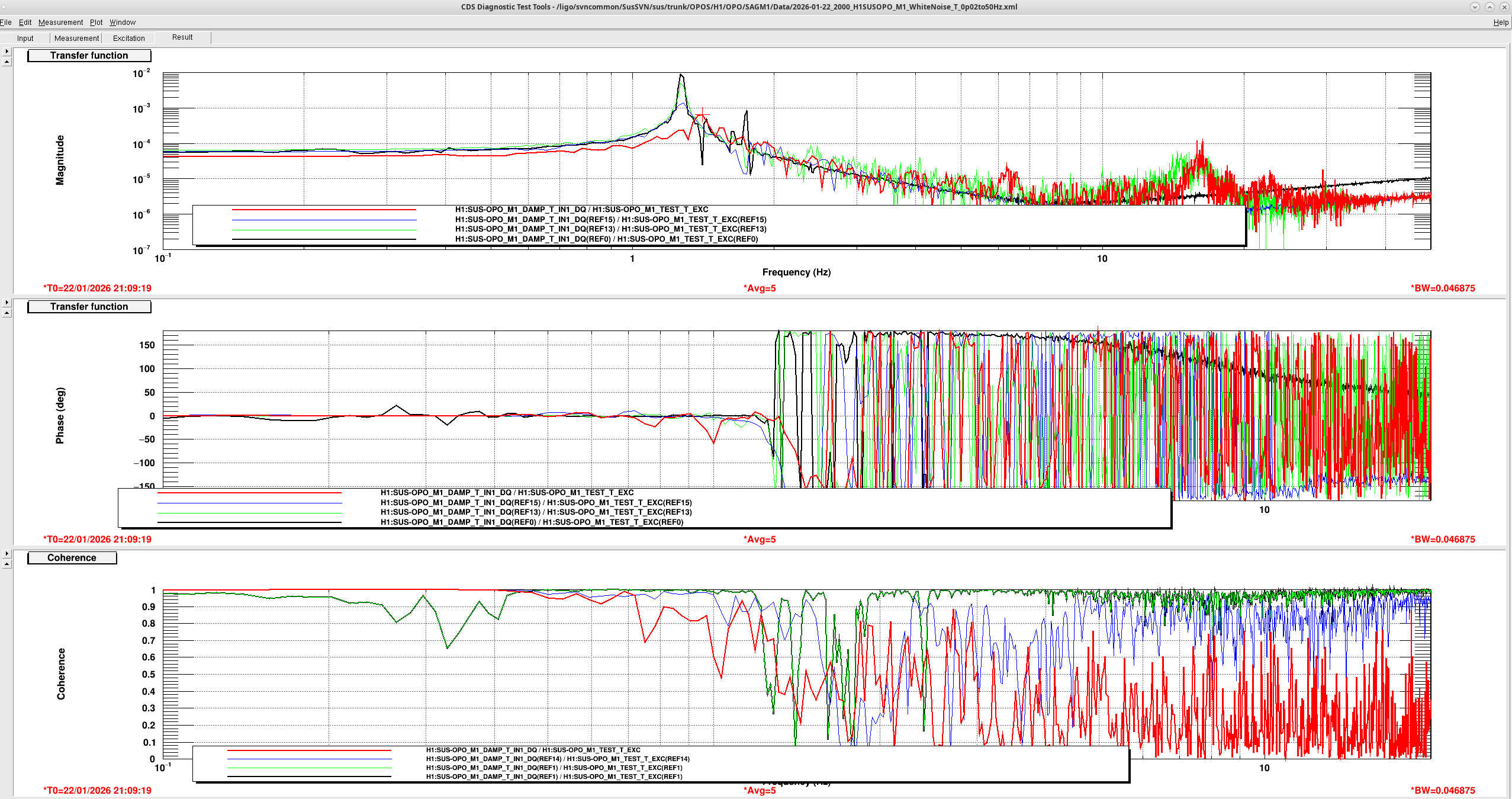
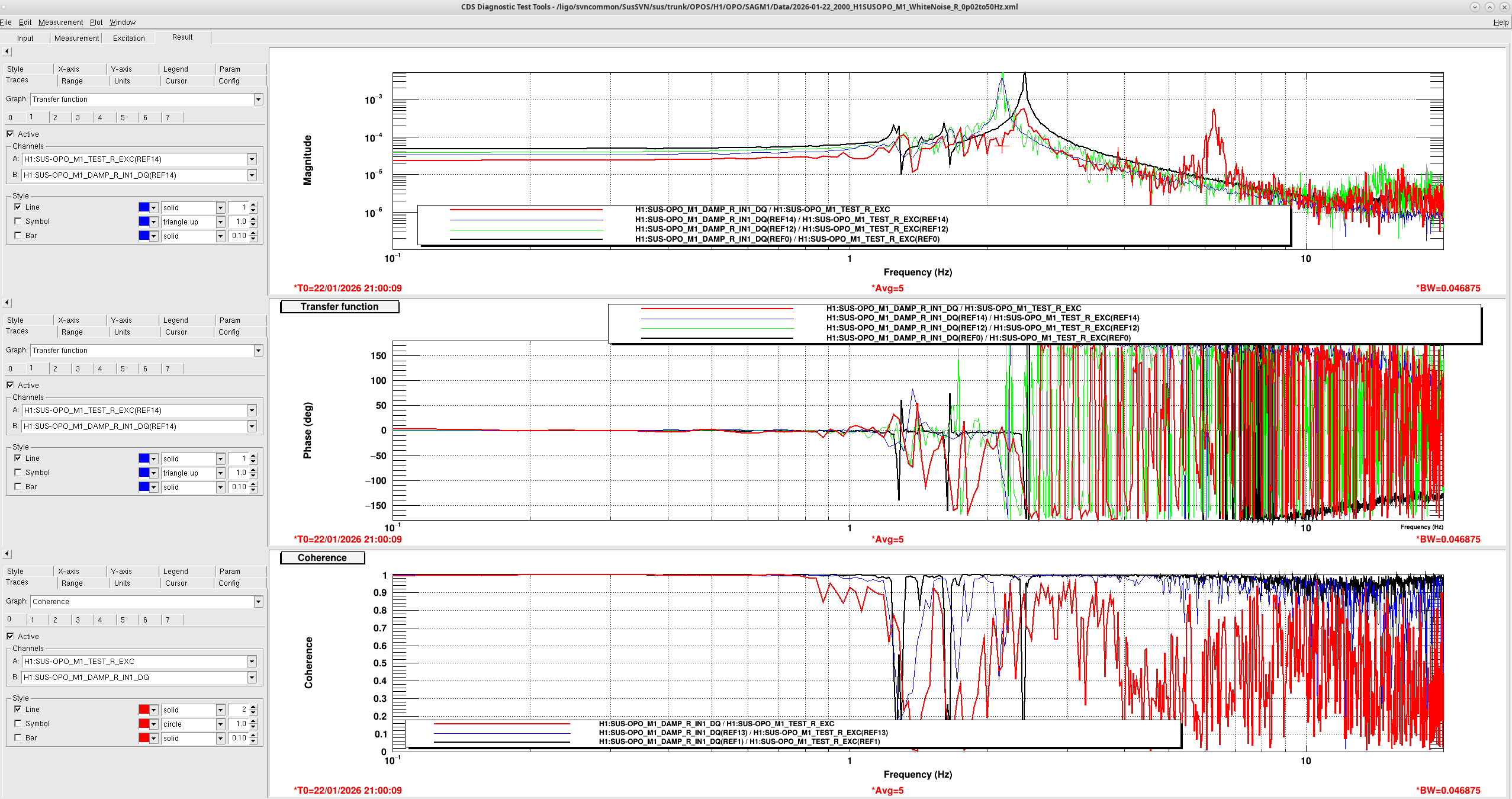
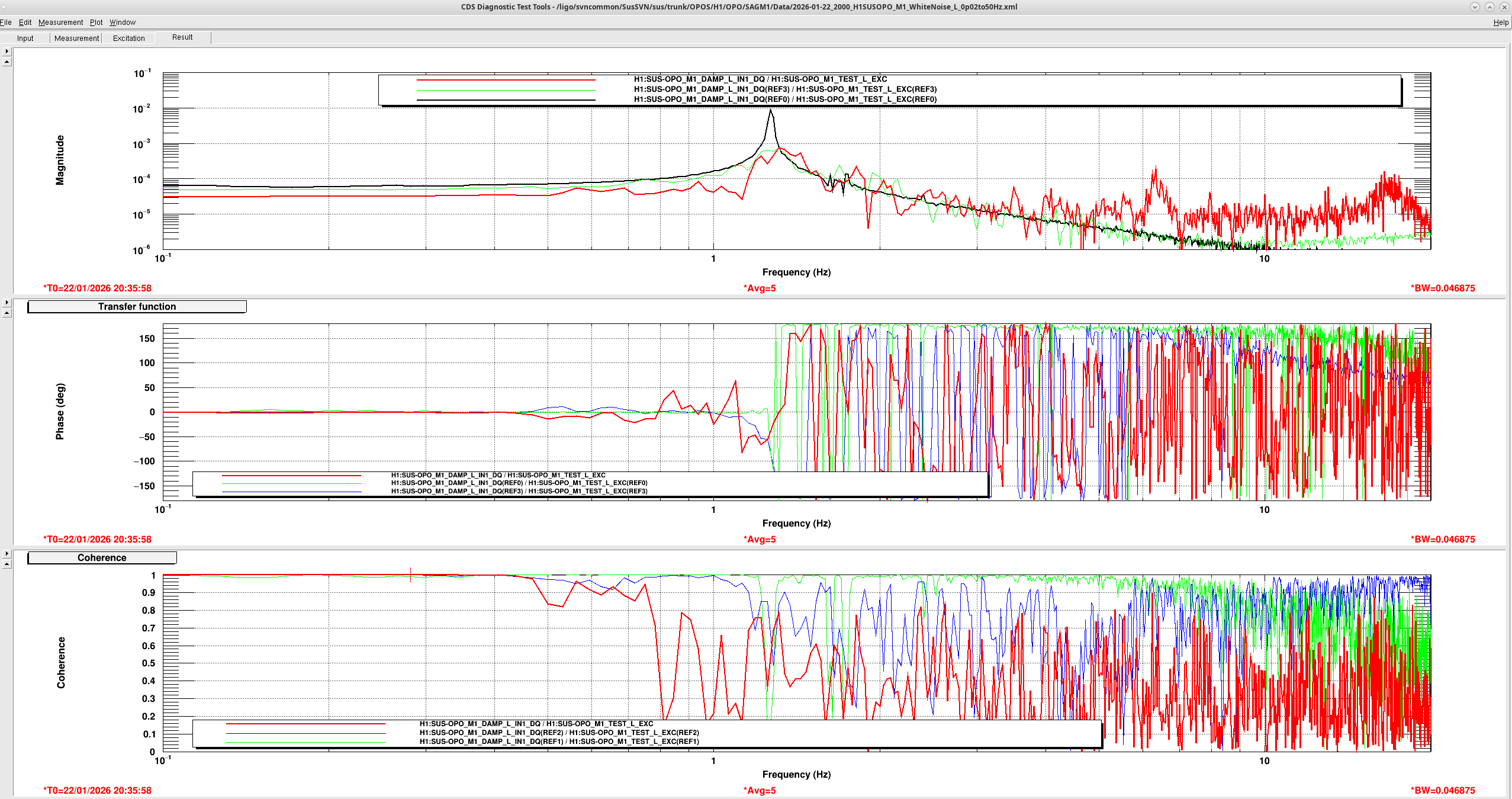
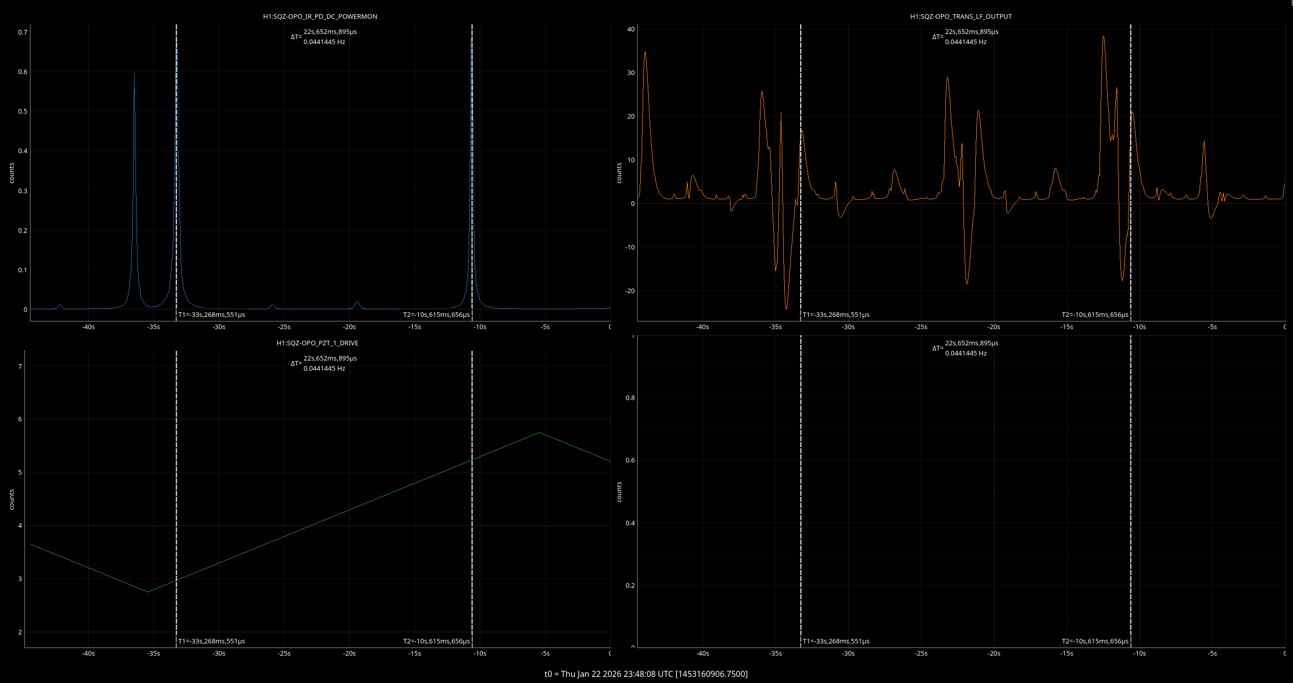
J. Kissel, R. Short

Trying to chase down the issues Ryan Crouch was seeing in his attempt at health check TF measurements of the OPOS (88851), I found that there were no OSEMINF OFFSETs and GAINs to compensate for the OSEM sensors' "open light" current (OLC).
Trending back, this suspension has hasn't had OLC compensating OFFSETs or GAINs since we migrated it from HAM6 to HAM7 circa 2021.

However, there are TFs in the measurement library (list ${SusSVN}/sus/trunk/OPOS/Common/MatlabTools/plotallopos_tfs.m) in 2022, documented and compared to matlab model in LHO:64275, and they look great. This sadly makes sense, as the former open light current compensating gains were close to 1.0, and the "centering" offset to make the "flag is centered within the range of the OSEM sensor" equal to 0 doesn't really matter for a driven transfer function or ASD, since these both don't care what the DC value of the sensor is, as long that sensor doesn't saturate during the measurement (i.e. the raw ADC counts are somehwere around +15000 [ADC ct]).

There's several reports -- over the years as HAM7 has been occasionally open -- how incredibly inaccessible the AOSEMs are within the suspension, and thus every attempt to gather new open light current values are thwarted by "we don't have time for that" or "I tried and it'll require interfering with way too much other stuff." Examples of this are  the 2021 attempt by Keita / Camilla (LHO:59939) and last week's undocumented attempt by Rahul (while he was in HAM7 to relieve the yaw offset on ZM4; LHO:88788).

Even worse, prior to the move to HAM7, during the installation in HAM6 circa Feb 2018 (LHO:40727) the new OSEMs AOSEMs saturated the ADC at olc = +32768 [ADC ct], so we installed relatively meaningless compensating OFFSETs and GAINs of -olc/2 = -16384 [ct] and 30000/olc = 0.916 [ct/ct], for all but one -- the V3 sensor which was set to -15481 [ct] and 0.973 [ct/ct]. In Apr 2018, we found that the V2 AOSEM's flexi-circuit V2 OFFSET and GAIN was changed to -14553 [ct] 1.031 [ct/ct] in Apr 2018 (see LHO:41468, LHO:41470 and LHO:41503.

So this has been left as wrong for 5 years. And really, prior to that, inaccurate.

Citing me from 2021 -- the OPOS is using the same AOSEMs and sat-amps as it did while it lived in HAM6, the only difference in the open light current will be from the cable length difference between HAM6 to SUS-R4 and HAM7 to SUS-R4, which I suspect is negligible.
So let's at least restore the "inaccurate."

But in short, assuming no LED light lumin decay, I think the "correct" values -- and the values that I've now re-installed -- are
   OSEM      OFFSET      GAIN
    H1       -16384      0.916
    H2       -16384      0.916
    H3       -16384      0.916
    V1       -16384      0.916
    V2       -14553      1.0307
    V3       -15481      0.973
These have been accepted in the SAFE and OBSERVE.snaps

So, the question that now remains whether the AOSEM LEDs have decayed significantly, but that -- as we every suspension we ever try to assess -- is horribly confused by alignment shifts (intended or not), making it essentially impossible to assess. The OPOS is no different.
The flags physical relationship to the OSEM sensor / LED is wherever they are, with the chamber in-air at the moment. Comparing the last relatively pre-chaos period to now,
        2025-12-04    NOW
        Under UHV     In-air
H1      7904          8488
H2      8831          7431
H3      8482          3106
V1      14934         14088
V2      13534         11864
V3      12618         9824

In between the "reference" times above, there have been a series of major alignment shifts of the suspension (see last attached), as reported by the OSEM ADCs, for the following reasons:
   2025-12-04 18:03 UTC H567 Mega-clean room turned on, causes all the OSEMs to drift over ~7 days.
   2025-12-04 20:23 UTC Site Power Outage, brief outage, but
   2025-12-10 00:46 UTC HAM7 Door pulled off
   2025-12-10 18:50 UTC OPOS locked down in prep for removal of OPO cavity for crystal swap
   2025-12-12 23:41 UTC Removal of OPO cavity for crystal swap

   2026-01-20 21:34 UTC OPO is reinstalled, OPOS is unlocked
   2026-01-21 19:02 UTC On-platform adjustment of optics, reasonable to expect alignment shifts
   2026-01-22 22:15 UTC More on-platform optic adjustments, reasonable to expect alignment shifts
All this makes it tough to say what the "right" position of the OSEMs should be, and whether e.g. having a raw OSEM count of 3000 [ADC ct] on the H3 OSEM is "acceptable."

Acknowledging that there's very little range on the H3 OSEM right now, I'll try reducing the excitation amplitude.

However, while we have the chamber open, I recommend re-centering the AOSEMs.

Other "interesting" aLOG references.
2022-08-02 LHO:64275 Post HAM7 install health checks in Feb, May, and Aug 2022 show a reasonable, and coherent set of TFs that match the model. Even without OFFSETs or GAINs.
2021-10-27 LHO:60422 Bug identified in OPOS OSEM2EUL/EUL2OSEM basis change matrices. Identified, but never implemented.
2021-09-17 LHO:59939 Attempt to measure open light currents after installation into HAM7, but inaccessibility of H3/V3 OSEMs thwarted effort.
2021-08-26 LHO:59741 OPOS Lands in HAM7
2021-08-17 LHO:59752 OPOS Front-end Infrastructure Migrated from HAM6 (h1susopo) to HAM7 (h1sussqzin)
2021-08-17 LHO:59652 h1susopo model is brought down for above migration to new model -- HERE'S WHERE OPOS OLC OFFSETs and GAINs were lost.
2018-02-26 LHO:40727 Generic 16384 ct OFFSETs and 0.916 GAINs installed because new AOSEMs saturated the ADC during open light.
2018-04-17 LHO:41470 V2 OSEM replaced, new OSEM has non-saturating OLC values
Images attached to this report


Comments related to this report
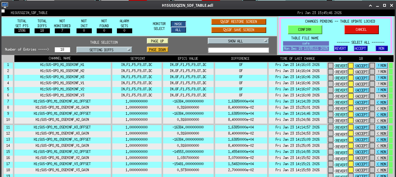
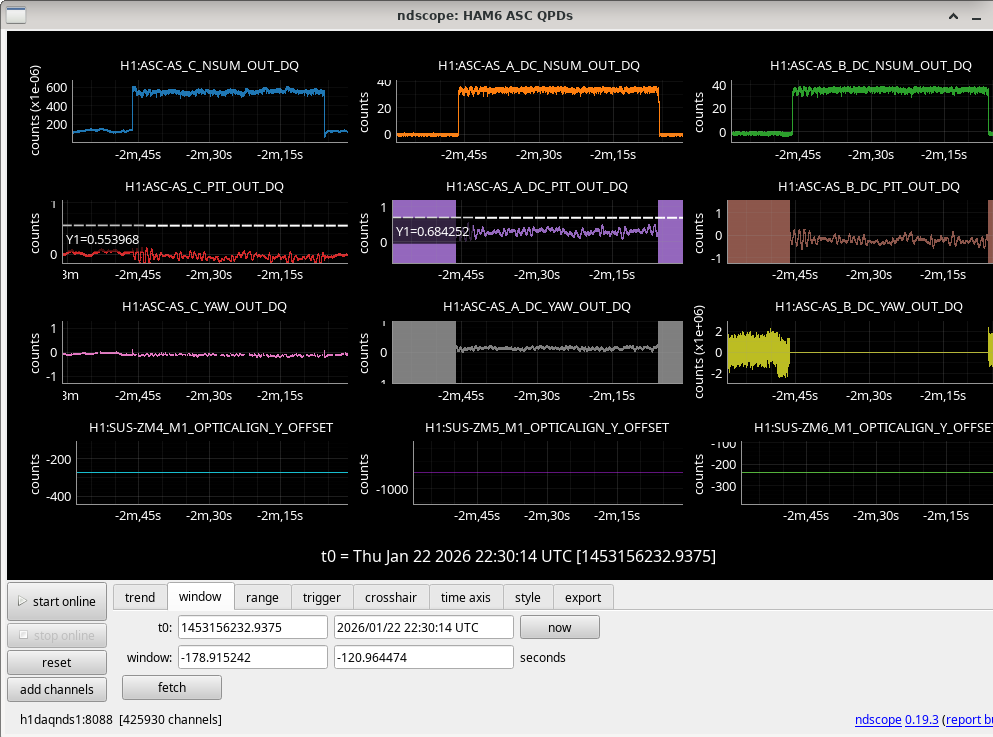
Screenshot of accepting above-mentioned OPO OSEM offsets and gains in the h1sussqzin model attached. This model's safe and observe tables are linked.
Images attached to this comment


