TITLE: 06/08 Day Shift: 15:00-23:00 UTC (08:00-16:00 PST), all times posted in UTC
STATE of H1: Lock Acquisition
CURRENT ENVIRONMENT:
SEI_ENV state: CALM
Wind: 11mph Gusts, 8mph 5min avg
Primary useism: 0.01 μm/s
Secondary useism: 0.07 μm/s
QUICK SUMMARY: IFO unlocked about an hour ago and Camilla has been struggling with ALS since. Troubleshooting.
After noticing a "double-spot" on one if the ITMY HWS points on May 26th, Dan suggested turning off the HWS SLED to understand where this scattered light is from. seems to have been there since 08 April ~19:30UTC.
Tonight I turned off the ITMY SLED 7:46 to 8:02UTC and 10:54 to 11:01UTC and the ITMX SLED 10:50 to 10:57UTC. After ALS has been shuttered and with both HWS SLEDs off.
Unsure what this light is. We could try turning down the HWS camera exposure to minimize some of it.
STATE of H1: Lock Acquisition
H1 range channels and SenseMon are down 70271.
Control room channels H1:CDS-SENSMON_CAL_SNSW_EFFECTIVE_RANGE_MPC and H1:CDS-SENSMON_CLEAN_SNSC_EFFECTIVE_RANGE_MPC have not been reporting correct values since 08:21UTC, see attached.
The SenseMon Range FOM is reporting range fine is also frozen at time 08:19UTC, see nuc27 screenshot attached. Omicron glitches are not updated as well.
The SenseMon and Omega problems seem to be related to a error in the /gds file system (seems to be unmounted). I have notified Dan Moraru via mattermost and email, but I'm not sure when he will see those messages.
Noticed that although ISC_LOCK requests CAMERA_SERVO to go to CAMERA_SERVO_ON in state 578 (ADS_TO_CAMERAS), the CAMERA_SERVO gets stuck in DOWN as is returning False unil we are in NLN. The ADS scopes show the dither is on during this time, even if the CAMERA_SERVO guardian doesn't refect that. See attached plot of CAMERA_SERVO staying in DOWN as it's status is not ready.
If we want to go to the camera servo in ADS_TO_CAMERAS we should edit the NLN checker in DOWN, DITHER_ON, TURN_CAMERA_SERVO_ON and CAMERA_SERVO_ON. This will save us ~1 minute to get to Observing if ADS has already converged (happens if we pause to damp violins while locking).
TITLE: 06/08 Owl Shift: 07:00-15:00 UTC (00:00-08:00 PST), all times posted in UTC
STATE of H1: Lock Acquisition
CURRENT ENVIRONMENT:
SEI_ENV state: CALM
Wind: 5mph Gusts, 4mph 5min avg
Primary useism: 0.01 μm/s
Secondary useism: 0.08 μm/s
QUICK SUMMARY: Just lost lock at 06:53UTC 1370242452 after 2h49 in NLN. Ryan and I watched CSOFT P ASC control signal ring up before the lockloss, plot attached. Tagging ISC.
VAC, SUS, SEI, CDS, dust monitors all Okay.
Looked over the last locklosses. In general the CSOFT_P control signal does get larger throughout the lock. In particular the last three "unknown" locklosses show CSOFF_P_OUT16 getting up to 4000 in towards the end: this one along with 20230608 0245UTC and 20230608 0653 UTC.
20230607 1635 UTC shows some CSOFT P noise but not as bad. The other locklosses in the last 3 days CSOFT_P_OUT16 stayed below ~2000.
Plot of last 3 days attached. Did something change during at the "1 day ago" 06/07 09:37UTC? This was the second lock after maintenance and I moved PR3 to get locked 70217.
TITLE: 06/08 Eve Shift: 23:00-07:00 UTC (16:00-00:00 PST), all times posted in UTC
STATE of H1: Observing at 133Mpc
SHIFT SUMMARY:
Lock#1
We aquired NLN at 23:00UTC and went into observing at 23:03UTC, we went out of observing at 02:45 due to a lockloss.
Lock#2
Xarm went through increase flashes (~5minutes), then we went through PRMI which locked fairly quickly then DRMI locked.
The lockloss rang up a violins a bit so we had to wait in OMC_WHITENING for them to damp just like in the last lock
NLN at 04:04 UTC, in observing at 04:07UTC
Chris swung by to turn off the water pump from 23:05TUC to 23:15
LOG:
| Start Time | System | Name | Location | Lazer_Haz | Task | Time End |
|---|---|---|---|---|---|---|
| 21:19 | VAC | Gerardo | Ends | n | Get reading at LN2 tanks | 21:49 |
| 22:04 | FAC | Christina | LSB to VPW | n | Forklift crates while out of lock | 22:24 |
| 00:54 | Rick | Arms | N | Bike ride | 01:34 |
Summarizing some thoughts regarding the sqz levels at LHO going into O4. Best-case, we've observed up to 4.5dB DARM noise reduction with squeezing at 50W and 60W. Ignoring phase noise, this 4.5dB sqz is about 30-35% total sqz losses (~19% known, ~15% mystery). At 76W at start of O4, we've typically seen 3-3.5 dB at high frequencies, and almost up to 4dB once (we can hopefully recover this after fixing on-table alignments). Some of the major questions that I'm thinking about, towards more squeezing at LHO:
Re: #2, technical noise in the IFO. At some point I compared the 64 kHz channel DCPD noise spectra from various IFO configurations, see screenshot. I think the main points of comparison are:
- green trace: 60W before TCS tuning , middle (dcpds 20mA)
- pink/blue traces: 60W after TCS tuning , lower , no sqz (red) / sqz (blue) (dcpds 20mA)
- red/cyan traces: 76W, middle of ER , upper, no sqz (pink)/ sqz(cyan) (dcpds 40mA)
There's a lot going on and a lot of confusing things. My only real take-away so far is that broadband technical noise was better with the TCS / ETM ring-heater tuning at 60W (68236), which coincided with sqz levels quickly going from 4dB to 4.5dB. I don't know how DCPD total mA factors into this. Overall, the spectra looked better by ~3dB at 5kHz, and ~5-15dB above 7kHz. I think the relation might just be that the broadband noise reduction w/TCS makes the IFO more shot-noise-limited, and so we can directly observe more squeezing in DARM (ie, w/o subtraction).
I'm not sure how mode-matching plays into all of this, but I wonder also if we can learn stuff looking at the broadband technical noise around various higher-order-mode peaks.
I've turned off some empty filters modules that were engaged following LHO70179 for some violins modes (ETMY9, ETMY19, ITMY18, ITMY19), damping (SUSETMY) and monitoring (SUSPROC) filters. I've accepted the following in SAFE and OBSERVE.
STATE of H1: Lock Aquisition
In observing at 23:03UTC out at 02:45UTC from the lockloss
We had a fast lockloss at 02:45UTC, DCPC saturated right beforehand. No obvious reason for the lockloss.
J. Kissel
There's an on-going debate whether we prefer 76 W (now 75W) PSL input power vs. 60 W PSL power, because we think that we had better noise performance at 60 W. It's a great debate, and I'm all for it. One thing I want to make super clear -- the lack of duty cycle during the engineering run and through the start of O4 has *NOT* been because of the increase in power from 60W to 76W. We've had one heck of a couple of months in terms of
(1) An insidiously slow drift in yaw on all of our HAM ISIs due to an innocent oversight of a foton-induced copy-and-paste error in ISI RZ blend filters (now fixed)
(2) Literally every Tuesday for the past 4 Tuesdays, we've had a 1 deg C (~1-2 deg F) rapid temperature excursion in the LVEA, and some not even on Teusdays
(3) A particularly earthquake full couple of months
(4) We've had 3 or 4 inadvertent, system-wide, inter-computer communication "dolphin" crashes, sometimes causing a day of confusion from settings lost
(5) Several electronics chassis fail all inadvertently
Further, (1) and (2) caused all sorts of apparent trouble that we interpreted as PR3 alignment / ISCT1 alignment troubles, and thus there may be some residual noise knock-on effects as a result.
Indeed, though I don't yet have the quantitative evidence to prove it, I think our issues with (1) and (2) drove us to move PR3 into a different position -- which in turn pushed the arm cavity spots to a different position onto a different point absorber/ acoustic mode situation -- which in turn caused our problems with "a new PI" at the start of the run -- and drove the choice to decrease the ETMX Ring Heater power -- which then drove us to decrease the power from 76W to 75W.
All of these issues cropped up right around the increase in power, and have continued through the start of the run, so I think some -- including myself -- had gathered an incorrect impression that H1's low duty cycle at the start of the run has been because of the power increase. With the trends in this aLOG, I argue it has not.
Check out the attached past 3 months worth of trends, in both relative time axis and absolute UTC time axis.
Remember, the observing run starts -15 days ago, or on May 24 2023 at 15:00 UTC.
1st panel: IMC input power, in Watts, showing the transition from 60W to 76W
2nd panel: residual HAM-ISI position in RZ, in nanoradians, showing the 10-20 urad drift of the tables due to (1)
3rd and 4th panel: temperature zones in the LVEA, in deg C and deg F, respectively, showing the last 4 Teusday's worth of temperature excursions
5th panel: all test mass ring heater power level settings, in Watts showing the early explorations of ring heater settings after power up, and the ETMX reduction during the HAM ISI alignment excursion (the upper half is shown, but both upper and lower halves are set equally each time)
6th panel: 0.03 - 0.1 Hz BLRMS of the ground motion at each of the three buildings, showing the "earthquake and wind" band, highlighting (3)
7th panel: PR3's yaw alignment slider, indicating that we've been steering PR3 around all over the place only in the past 4 weeks, likely a result of the ISI yaw drifts (1) and temperature excursions (2).
Adding another dimension to the problem... I was thinking over night about this, and realized "well, maybe there's *one* part of the power increase that has impacted duty cycle; the 11 Hz ring ups from PRCL going unstable thru too much gain." But, I've added the PRCL gain adjustments to the series of trends -- see new attachments in relative time and UTC time -- and I think the new-ish PRCL instabilities can also be explained by drifts and changes in alignment. - We started using the THERMALIZATION guardian around Apr 24. This slow ramps the PRCL2 gain through the thermalization period - We made a change, *reducing* the PRCL2 end-point setting on May 21 -- but this was reactive to the time when the ISI YAW drifts were at maximum. - We then restored that end-point setting on May 26 - Then, on May 31, after having starting to have trouble with 11 Hz ring ups of PRCL gain, we adjusted the "base" PRCL1 gain from 1.0 to 1.5, -- but this was reactive is after several days of LVEA temperature drifting around between May 25 and May 31, and an especially bad Tuesday on May 29th. - On Jun 4th, the LVEA temperature controls settle on a "new normal" and we "find" we need to increase the "base" PRCL set point again to 1.7 on June 6 - Then on Jun 7th, we reset the "base" PRCL1 gain to 1.0, but instead increase the thermalization set point higher. My vote is the following: we take the hit in time that this will mean: - Restore (or change to re-create) the LVEA temperature to values we had consistently for months up until May 10th. Since the LVEA is en-mass cooler than before, we can use the individual zone heater settings to bring each zome back *up* to is "prior to May 10th" value. - Once that's settled, we re-align PR3 YAW to the slider values we had up until May 10th of 151.6 "urad," and run an initial alignment. - Once that's settled, we go out to ISCT1 and re-reset the alignment of the table (though it's not reproducible, hopefully, doing so will get us back to the ISCT1 alignment we've had for many moons prior to all this mess). - Once that's settled, restore ETMX ring heater to its value of 1.3 W. - Once that's settled, we go back to the May10th era PRCL gains and THERMALIZATION guardian set points of PRCL1 = 1.0 and PRCL2 = 23.0. If all that works, then we re-calibrate PR3's sliders, optical levers, and OSEMs.
Since it's perhaps quite tough to see all these traces stacked vertically on top of each other (a regrettable "must" because the timing of all these changes is important to the story) I've capture this epic ndscope session as a .yaml template.
/ligo/home/jeffrey.kissel/2023-06-07/
2023-06-07_3motrend_IMCPWR_ISIYAW_LVEATEMP_GNDBLRMS_PR3YAW_PRCGAINs.yaml
I can't attach a file with the ".yaml" or ".yml" extension to the aLOG, but it's linux, so I've just changed the file extension to .txt (because, in the end, it *is* just a text file). So if you'd like to download it from here and look around, download and then change the extension back to ".yaml".
With the temperatures more stable then they had been we are waiting to get the cooling coil strainers cleaned before attempting other changes. The major flucuations we were seeing we caused primarily by a cooling coil not getting to temperature creating an issue for mulitiple days. Once the strainers are clean temperature control can be changed to try and recreate previous zone temperatures. Though it was nice have all zones grouped together for once.
There have again been a few instances of the 4.05 Hz harmonics that were tracked to scattered light from the ETMX cryobaffle (alog 69578) and mitigated by making changes to the fans (alog 69635). They appear slightly different on the summary pages now because they now use cleaned h(t) which makes the harmonic at 16 Hz visible. The spectrum looks otherwise the same.
TITLE: 06/07 Day Shift: 15:00-23:00 UTC (08:00-16:00 PST), all times posted in UTC
STATE of H1: Observing
SHIFT SUMMARY: Just got back to NLN from a lock loss. Recovery today has been mostly hands off. The lock losses today are still unknown and need more people to keep looking at them.
LOG:
| Start Time | System | Name | Location | Lazer_Haz | Task | Time End |
|---|---|---|---|---|---|---|
| 15:40 | FAC | Tyler | OSB Mech room | n | Checking in air handlers | 16:01 |
| 21:19 | VAC | Gerardo | Ends | n | Get reading at LN2 tanks | 21:49 |
| 22:04 | FAC | Christina | LSB to VPW | n | Forklift crates while out of lock | 22:24 |
J. Kissel E.J. identified recently that there were some filter modules which were requested to be ON, but had no filter in them -- see LHO:70179. Between lock stretches, I reviewed the H1OAF filter banks, Front-end Filter Bank Module Function h1oaf : 'OAF-CAL_SUM_DARM_L1', 'FM3', An old, very much defunct, uncommissioned, and unused version of the DARM calibration 'OAF-CAL_SUM_DARM_L1', 'FM6', 'OAF-CAL_SUM_DARM_L3', 'FM3' h1calcs : 'CAL-CS_DARM_ANALOG_ETMY_L1', 'FM4' An unused, out-of-date filter bank for calibrating ETMY's UIM stage (which is not currently out DARM actuator) And found that they can be safely turned off without issue. I've turned these filter requests OFF and accepted that "offness" in SDF to reduce confusion. Both h1oaf and h1calcs are one of those front-ends whose OBSERVE and safe.snaps are the same, so accepting is good enough preserve this setting.
Lost lock at 2107 UTC - 1370207267
No immediate cause for this yet.
Using the lockloss select tool, I saw that ASC-SRC2_Y seemed to step out a bit further than usual, ASC_AS_C feeds into SRC2_Y and it's read at OM1 from our Optical Sensor Layout (DCC G1601619). OM1 appears to show some abnormal motion seconds before the lockloss? But trending back further, this behavior shows up in the 2 previous locklosses (16:35UTC, 09:07UTC) too althought not as strongly, so maybe it's just another witness?
I think the recent issues with squeezer pump ISS railing are likely resolved after today's on-table realignments. The green pump AOM was significantly clipping the beam (SQZT0 layout here, "GAOM1"), both reducing the total power after the AOM, and degrading the fiber coupling efficiency due to the clipped+bad mode shape. See GAOM1 sweeps from this morning (before aligning, left) and now (after, right). Along the pump path, we now have better GAOM1 throughput (~90%), comparable diffraction efficiency (~60%), and improved fiber coupling. For 60uW opo trans we've been using, we previously launched 22mW with no buffer (hence iss railed); now we only have to launch 15mW for the same opo transmitted power, with lots of buffers.
GAOM1 typically has ~90% throughput, e.g. previously this was 14.4mW out from 16mW incident. Today I first measured 25mW out for 44mW incident (~57%): this means >30% of power from SHG was clipping on the AOM apeture. After re-aligning GAOM1 using the mount screws, we're back up to 40mW out for 45mW incident, so almost 90% throughput again. I think this could be better, but good enough for now.
Relieving the clipping also significantly improved fiber coupling efficiency, presumably b/c it improves the mode shape, as we are using the 0-th order AOM mode for pump light, and not the nice diffracted order that gets cleaned up in the diffraction. So aom clipping shows up on the beam we are trying to fiber couple.
-- Before, for 20mW into the pump fiber, we had 1.8mW on OPO_REFL_DC_POWER on the other end, with GAOM1 driven at 2-3V (almost no room), and all power on that path going into the fiber (SHG_REJECTED = 0mW).
-- After, for 20mW into the pump fiber, we have 2.9mW on OPO_REFL_DC_POWER (60% higher power), with GAOM1 driven at 4.5V (mid-range), and a healthy buffer of rejected power on the fiber path (SHG_REJECTED = 8mW).
I've upped the generated sqz levels, back to more "normal", hopefully nominal, values. In $(userapps)/sqz/h1/guardian/sqzparams.py, Line 12, I've set opo_grTrans_setpoint_uW = 85, and re-tuned the OPO co-resonance temperature at this pump power (temp decreased from 31.7C to 31.68C, expected as the higher power heats the opo crystal more).
This OPO green trans setpoint of 85 uW corresponds to a generated SQZ level of about 15 dB, or non-linear gain of 12.3. By comparison, 60uW ~ Gen SQZ = 12dB ~ NLG 6.4. So, this is nearly doubling the squeezer gain, aka increasing the generated squeeze level by about 3dB.
To check whether pump ISS failures are from aom clipping in the future, we can try the following. SQZT0 medm stuff should look like this screenshot, with teal circle highlighting the path we're talking about, and red arrows showing some knobs to turn.
1) Bring SQZ_OPO_LR guardian "DOWN". Now PUMP_ISS is disabled, so GAOM1 box is yellow.
3) Turn off pump fiber flipper.
2) Set H1:SQZ-OPO_ISS_DRIVEPOINT = 0. This turns off GAOM1 diffraction, and sends all power to the fiber (pump light uses 0-order).
3) See the total pump power after GAOM1 (sum of H1:SQZ-SHG_REJECTED_DC_POWERMON + H1:SQZ-SHG_LAUNCH_DC_POWERMON).
4) If GAOM1 is well-aligned and not clipping badly, I'd expect total power after GAOM1 to be about 70% of the SHG output green power, H1:SQZ-SHG_GR_DC_POWERMON.
Broken down, this ratio is from SHG's green output light (H1:SQZ-SHG_GR_DC_POWERMON) being split ~25% to FC green locking, and the remaining ~75% to the pump path GAOM1 which lets through ~90%.
I'm a bit suspious how this happened in this first place: I wonder if the beam is slightly large for the AOM aperture (but aom's throughput is not terrible), whether SHG or lab temperature drifts are changing the output alignment or mode-shape slightly, or whether we've bumped the SHG output path doing other on-table work. If ISS railing becomes a problem again at this SHG power, we can look into it more. For reference, we last increased SHG power by ~15% on May 16th (69671) in an attempt to resolve exactly this issue; we don't need all this shg power anymore.
Attaching quick SHG, OPO, CLF transfer functions taken after table alignments, with pd powers on medm.
Just following up on trends since this on-table AOM alignment -- this on-table fix seems to have mostly resolved the previous squeezer pump ISS issues.
There are a number of models with filters in modules that have been engaged but no filter has been defined for that stage. This causes some confusion when scanning for unresponsive filter stages, as these will clutter the results.
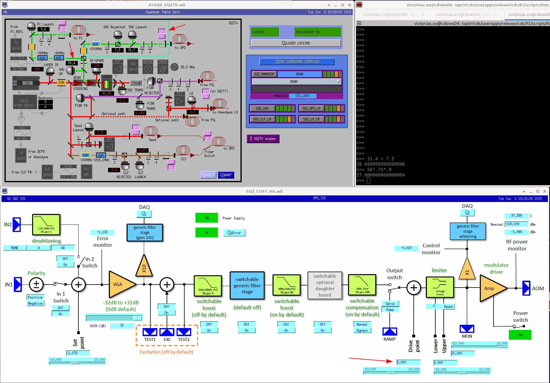
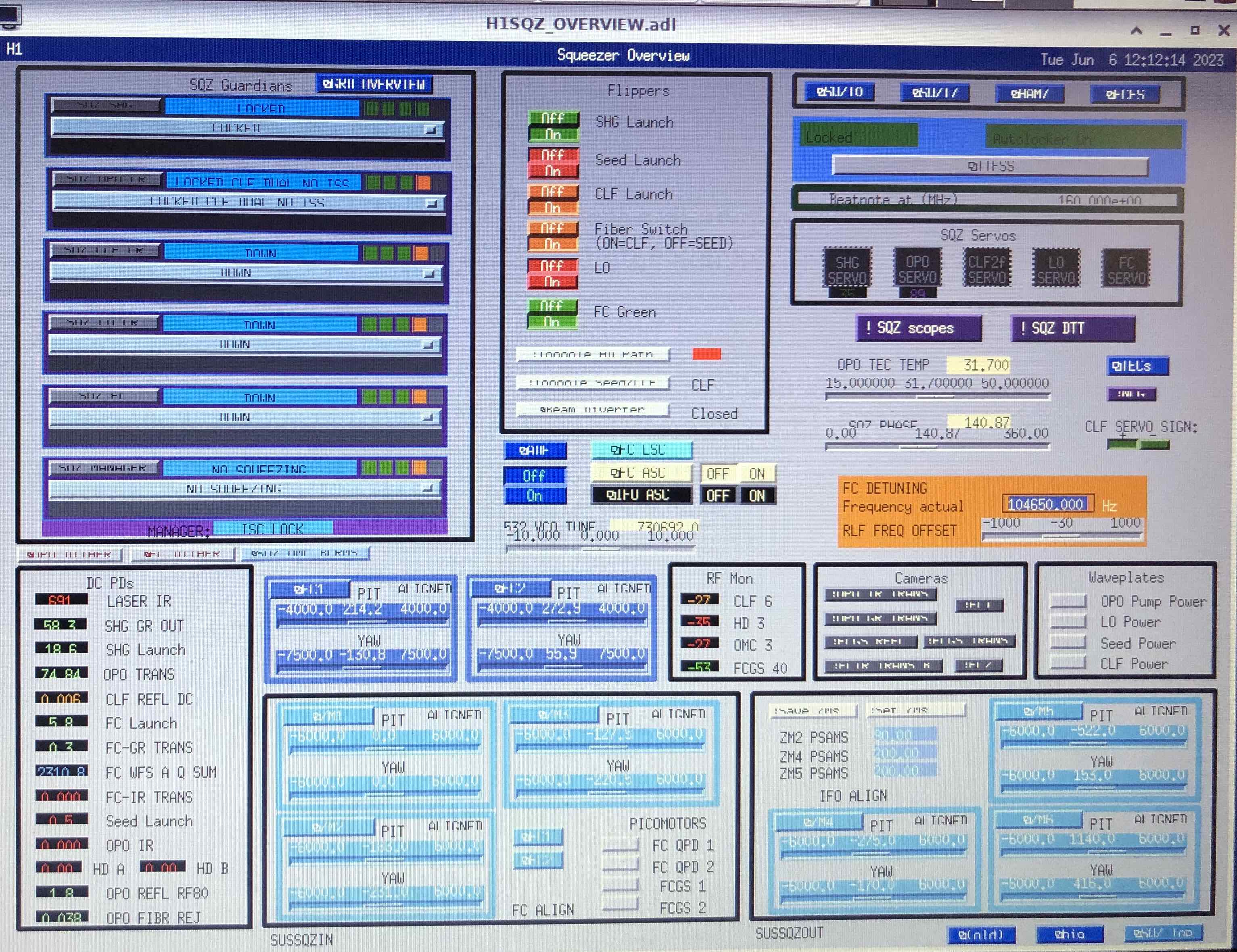
Attached is an example of what this looks like on the medm screen. FM2 is enabled, but nothing is loaded in that stage so the 2nd box never turns green.
My guess is that these stages used to have a filter defined for them, but were removed. The solution is to finish the removal of these stages, buy disabling the stage and saving the new state with SDF.
Full listing of filters/stages that are enabled but don't have the enabled stage defined in the filter file.
h1susetmy : [('SUS-ETMY_L2_DAMP_MODE19', 'FM1'), ('SUS-ETMY_L2_DAMP_MODE9', 'FM4')],
h1sussqzin : [('SUS-ZM1_M1_WD_OSEMAC_RMSLP_LL', 'FM6'), ('SUS-ZM2_M1_LOCK_L', 'FM6')]
h1hpietmx : [('HPI-ETMX_3DL4CINF_C_Z', 'FM1'), ('HPI-ETMX_3DL4CINF_C_Y', 'FM1'), ('HPI-ETMX_3DL4CINF_C_X', 'FM1'), ('HPI-ETMX_3DL4CINF_B_Z', 'FM1'), ('HPI-ETMX_3DL4CINF_B_Y', 'FM1'), ('HPI-ETMX_3DL4CINF_B_X', 'FM1'), ('HPI-ETMX_3DL4CINF_A_Z', 'FM1'), ('HPI-ETMX_3DL4CINF_A_Y', 'FM1'), ('HPI-ETMX_3DL4CINF_A_X', 'FM1')]
h1lsc : [('LSC-EXTRA_AI_2', 'FM2')]
h1lscaux : [('LSC-LOCKIN_1_DEMOD_9_I', 'FM1'), ('LSC-LOCKIN_1_DEMOD_9_Q', 'FM1')]
h1oaf : [('OAF-CAL_SUM_DARM_L1', 'FM3'), ('OAF-CAL_SUM_DARM_L1', 'FM6'), ('OAF-CAL_SUM_DARM_L3', 'FM3')]
h1calcs : [('CAL-CS_DARM_ANALOG_ETMY_L1', 'FM4')]
h1susproc : [('SUS-ETMY_L2_DAMP_MODE19_BL', 'FM1'), ('SUS-ITMY_L2_DAMP_MODE18_BL', 'FM1'), ('SUS-ITMY_L2_DAMP_MODE19_BL', 'FM1')]
Edited to remove any filter stages under local control.
Some filters have front-end control over which filters stages are on. Typically, more than one filter stage is used for, say a automatic boost, but only a subset is actually loaded. So, a filter may be on, but empty. This is the expected behaviour. Changing which filter stages are participating would be a front-end model change.
A better solution may be to turn the 2nd box on for empty filters, when they are on.
After reviewing all the "SUS" filter banks mentioned above, these empty filter banks are either on because they were turned on by mistake (the ZM1 and ZM2 filters) and blindly accepted into SDF, or the bank had never been active use for control or monitoring (the violin MODE control and monitoring filters), so someone was probably playing around with a filter design and cleared it out but forgot to turn off the filter. In all SUS cases, the filter module should be turned off and accepted as such in SDF. We'll make a point to clean this up and clear out the confusion next Tuesday, or during a next convenient lock loss.
h1sussqzin ZM1 and ZM2 filters in question have been turned off -- see LHO:70245.
h1hpietmx filters in question have been turned off -- see LHO:70251.
The h1oaf and h1calcs filters in question have been turned OFF -- see LHO:70255.
The h1susetmy and h1susproc filter modules in question have been addressed -- see LHO:70264.
To Daniel's point - Another choice is to populate the filter with a gain=1 stage. Then it turns on, but doesn't do anything. SEI does this with some of the calibrations. e.g. FM1 is the the manufacture's calibration, and FM2 is to tweak the calibration based on measurements. If the sensor is very close to spec, FM2 can just be a gain=1. Then all the automation works more smoothly.