FAMIS 25069
The inlock charge measurements again caused a lockloss (alog 70170) while swapping from ITMX to ETMX, but it was able to successfully do all 4 quads.
Jenne, Vicky. We took ~1 hour for sqz commissioning, from hours ~1-2 of lock.
Overall change is increasing the generated SQZ level from 12dB (60uW, last lock) to 14dB starting this lock (75uW). I don't think sqz is soley responsible for the lower range this evening (possibly some extra no-sqz noise). And, it feels like trends in the SQZ BLRMS are dominated by drifts of the technical noise and SRCL detuning over thermalization, so there isn't a clear correlation of more sqz = more range or better blrms. So while I do think more sqz is better, I think right now this test was probably limited by the elevated + drifting technical noise in the ifo, so I backed off the sqzing. Maybe with a thermalized IFO with stable technical noise, we'd see clearer trends of total noise vs. injected squeezing. Some notes from today:
We had Janos down at MidX/EndX from 23:10UTC to 23:23UTC turning off and putting away a pump. We reaquired NLN around this time (23:11) and saw some features on DARM that we weren't sure the exact cause of, such as a line at 105Hz. Tagging DETCHAR
WP11226 Mount spare NAT router
Jonathan:
The spare router was rack-mounted in the MSR.
WP11245 TW0 raw minute trend offloading
Dave:
I have started the copy of the past 8 months' raw minute trend from h1daqtw0's SSD raid to h1daqframes-0 SATABOY for permanent archival. The copy is expected to take several days.
nds0 DAQD was restarted to serve these files from their temporary location whilst the copy is onging. Other than nds0, there were no DAQ restarts today.
Tue06Jun2023
LOC TIME HOSTNAME MODEL/REBOOT
11:58:22 h1daqnds0 [DAQ]
(Jordan V., Betsy W., Gerardo M.)
The front door for the rack was successfully installed today. We could not determine the noise mitigation, because we finished at the same time the fire alarm started, so it was very hard to hear the net effect of the door installation.
A fiber chassis, installed at very top slot was affecting the door path, it protrude a bit thus prevented the door from closing, the brackets for this fiber chassis were removed, and the chassis gently pushed back enough to allow the door to close. This will be visited next week to determine if we can install the removed brackets in a different configuration.
Note: While at the rack, I noticed an "error screen" on the vacuum controls display, Beckhoff computer, see attached photo for more information regarding the error. I did not do anything with the screen, after taking a photo, I slowly walked away from rack, then I notified Patrick.
From a quick internet search it may be automatic updates running for Visual Studio. We should schedule a time to log in and try to disable them.
Per WP 11226 I mounted a backup router in the racks in the MSR. It is configured and ready to go. I have run connections from it next to the switching gear it would need to be connected to to be used. The spare router ended up being mounted in the h1-daq-1 rack instead of the network rack, this was due to the rack kit for the system needing to be deeper than the racks in the network rack. The basic procedure for switching to the router is in https://dcc.ligo.org/T2300212
I had a brief window to start installing feedthru protection on HAM8. Only got 2 of the 5 feedthrus. These are the 12" rings that go on the outside of the adapter plate, because the 12" adapters we got for this chamber don't have enough space around the 4.5" flanges to use the smaller feedthru protection. I didn't any pictures this time.
J. Driggers, J. Kissel, J. Oberling, T. Shaffer Executive Summary: We have used the ~4km arm length as a lever arm across the ~40 cm separation between ETMX ACB Baffle PDs to calibrate pitch and yaw of PR3's optic as reported by the PR3 M1 alignment sliders, M3 OSEMs, and Optical Lever pitch and yaw calibrations. They we *all* inconsistent. M1 Slider calibration changes by a factor of ~2, M3 OSEMs calibration changes by ~4, and optical lever calibration changes by a factor of ~8. We indicate the suggested correction to the calibration in the table below. We've not installed any changes, yet. We're waiting for folks to absorb and review this content, and to get ready for the change. Method (detailed blow-by-blow in 2023-06-06_OpticalLeverAlignmentCalibration.txt): (1) After the lock loss this morning, we went straight into using the INIT_ALIGN guardian to lock the X arm on read, and run the INPUT_ALIGN state. With PRM misaligned, this ensures that the PSL input beam is well aligned to the X ARM using POP WFS, and steers IM4 and PR2. We also checked and confirmed that the X ARM beam was well-centered the transmon QPDs. For us, the whole purpose of this was to make sure the PSL beam was steering through the center of the hole in the ETMX arm cavity baffle. (2) Took the INIT_ALIGN guardian to DOWN, and misaligned ITMX using the SUS-ITMX guardian. This then sets up a straight-shot, with no cavities, from PR3 to ETMX. (3) Unsure if we needed it, we also cranked up the PSL input power to 20 W. 
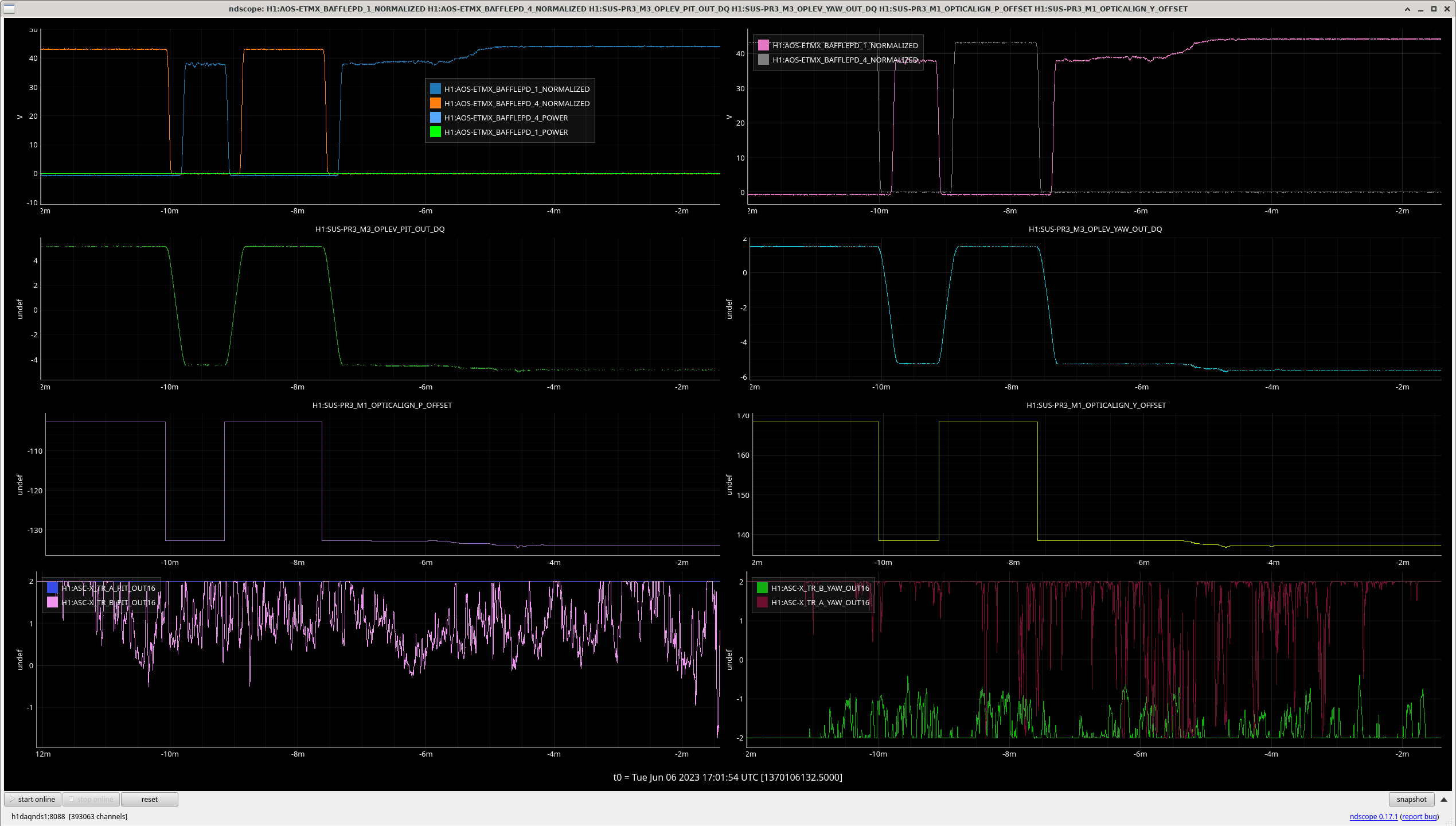
(4) We then slow rastered around the PR3 alignment sliders, looking for light to cross the ETMX Baffle PDs. (We confirmed PD1 and PD4 were alive by trending H1:AOS-ETMX_BAFFLEPD_1_NORMALIZED and H1:AOS-ETMX_BAFFLEPD_4_NORMALIZED, and saw that PD1 is typically saturated during nominal low noise around ~830 [ct], and PD4 is close, but still happily reading out real scattered light at ~550+/-50 [ct]. So, not knowing any better, we left them with a transimpedance of 2000 [ohm], and a whitening gain of +20 dB). 
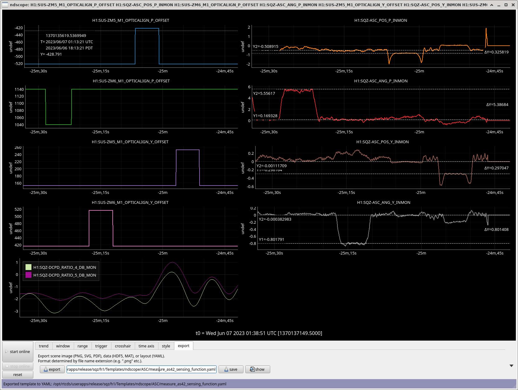
(5) Finding that PSL light on both PD1 and PD4 by steering the PR3 M1 OPTICALIGN alignment sliders a mere (and symmetric!) +15 ["urad"] in pitch and yaw (PD1 in -PIT,-YAW, and PD4 in +PIT,+YAW), we record the pitch and yaw values of (a) the sliders, (b) the optical lever
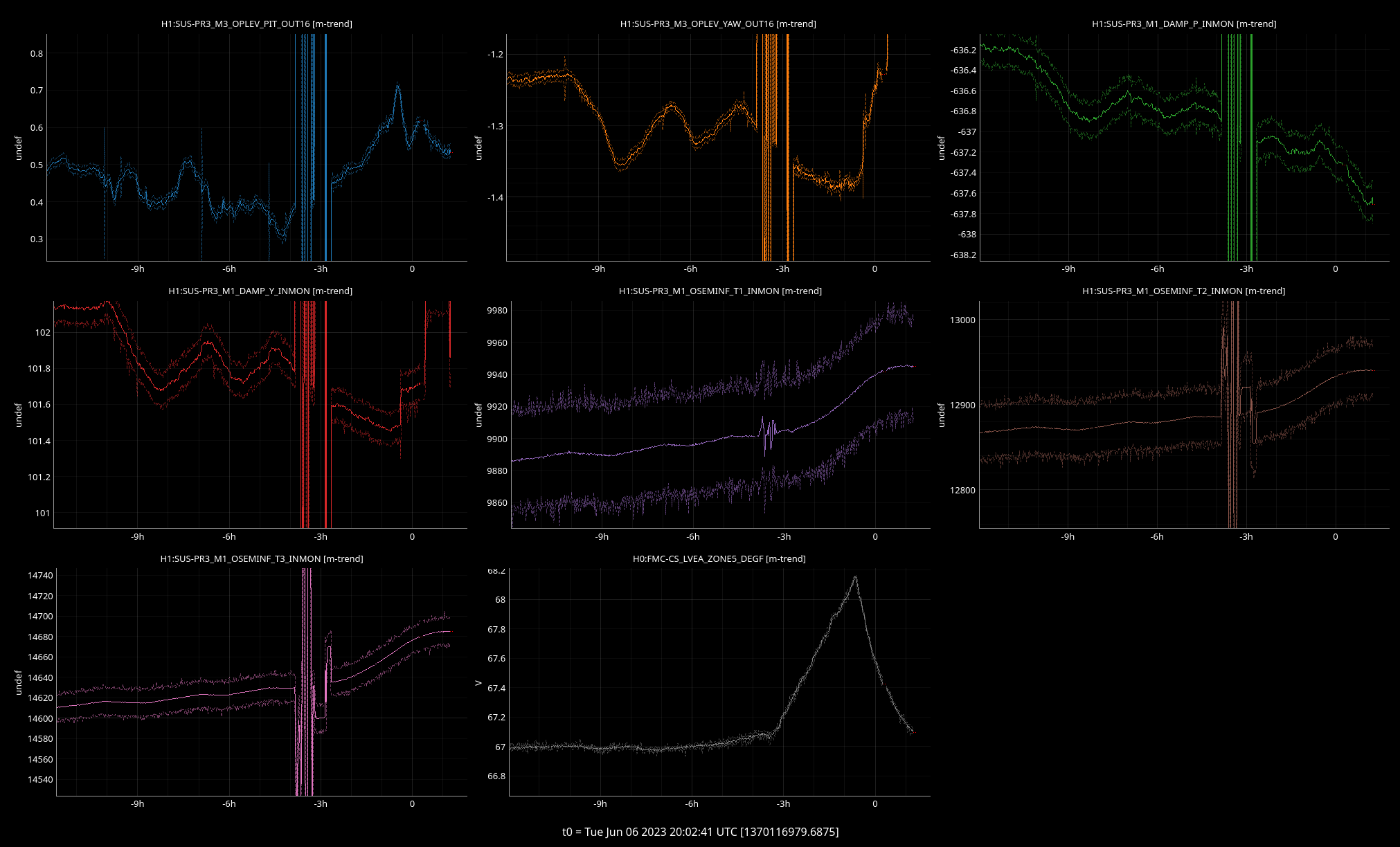
 (c) the M3 OSEMs 
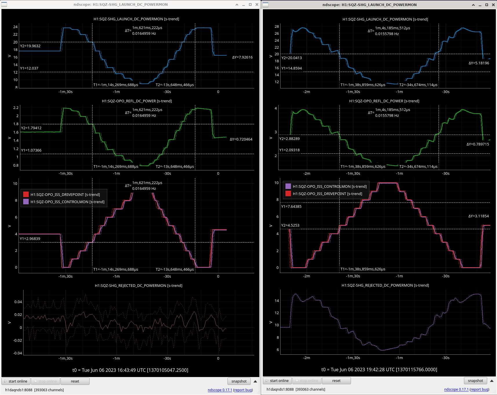
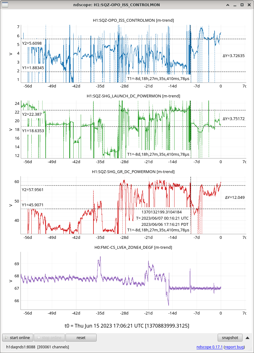
See attached trend of each of these things during those times. (6) Using these reported ["urad"] values, and comparing them against the physical [urad] from the center of the baffle's hole as determined by mechanical drawings of the PD separation and computing the distance from PR3 to the ETMX ACB as 4018.7135 [m] (see details in LHO:70177), we compute a correction to the calibration each of the sensors and actuators in order to reference against this highly precise (and quite accurate) angular reference. Results: POSITION: From LHO:70177 Slider Oplev M3 OSEM Time At [urad] ["urad"] ["urad"] ["urad"] Location Centered PIT 0.0 -117.7 +0.450 -482.992 Jun 06 2023 17:05:47 UTC YAW 0.0 +153.5 -1.355 +171.577 PD1 PIT -40.1 -134.0 -4.85 -493.754 Jun 06 2023 17:00:14 UTC YAW -37.2 +137.1 -5.61 +161.257 PD4 PIT +34.2 -102.7 +5.12 -474.888 Jun 06 2023 16:45:00 UTC YAW +37.2 +168.4 +1.52 +180.750 ----------------------------------------------------------------------- DISPLACEMENT (PD1 - Cent) PIT -40.1 -16.3 -5.3 -10.762 YAW -37.2 -16.4 -4.255 -10.320 (PD4 - Cent) PIT +34.2 +15.0 +4.67 +8.10 YAW +37.2 +14.9 +2.875 +9.17 (PD4 - PD1) PIT +74.3 +31.3 +9.97 +18.87 YAW +74.4 +31.3 +7.13 +19.493 ----------------------------------------------------------------------- CALIBRATION CORRECTION VALUE (PD1 - Cent) [urad/"urad"] PIT 2.4601 7.5660 3.7261 YAW 2.2683 8.7427 3.6047 (PD4 - Cent) [urad/"urad"] PIT 2.2800 7.3233 4.2222 YAW 2.4966 12.9391 4.0567 (PD4 - PD1) [urad/"urad"] PIT 2.3738 7.4524 3.9375 YAW 2.3770 10.4348 3.8168 ----------------------------------------------------------------------- CORRECTED CALIBRATION VALUE Suggested Update to Slider Calibration [(DAC ct)/"urad"] * ["urad"/urad] = ([DAC ct)/urad] PIT 2.675 * (1/2.3738) = 1.1269 H1:SUS-PR3_M1_OPTICALIGN_P_GAIN YAW 12.272 * (1/2.3770) = 5.1628 H1:SUS-PR3_M1_OPTICALIGN_Y_GAIN Suggested Update to Optical Lever Calibration ["urad"/(ADC ct)] * [urad/"urad"] = [urad/(ADC ct)] PIT 26.9 * 7.4524 = 200.47 H1:SUS-PR3_M3_OPLEV_PIT_GAIN YAW 29.6 * 10.4348 = 308.87 H1:SUS-PR3_M3_OPLEV_YAW_GAIN Discussion: (I) The slider vs. optical lever calibration correction is consistent with Sheila's suspicion that "the optical lever calibration is off by a factor of 4, based on the sliders" from LHO:70008. (II) We think the numbers derived from the the displacement between PD4 and PD1 are the most accurate numbers, so we suggest updating the sensor / actuator calibrations with these numbers (rather than the PD4-center, or PD1-center numbers). We're also confused / suspicious of the optical lever calibration correction values, given that they range from 6 to 12, where all other correction values are relatively consistent to within ~10%. We think this may be that the PR3 optical lever beam spot is close to the edge of the QPD. (III) We note that we're very suspicious of the YAW calibration correction factors for the optical levers. We think the PIT optical lever signal is very cross-coupled when driving YAW sliders, as much as ~0.5-1.0 PIT Oplev [urad] / YAW Slider [urad] (already correcting each by their respective calibration correction values list above). YAW optical lever per PIT slider is much less, around 0.04 YAW Oplev [urad] / PIT Slider [urad]. Reasons we brainstormed for this kind of cross coupling, (i) The QPD itself is clocked with respect to the beam spot's vertical / horizontal motion at the QPD (ii) The beam spot on PR3 is not centered (iii) The beam spot at the QPD has some astigmatism As a result of (II) and (III), Jason thinks it's worth it to look at the PR3 optical lever QPD in its housing on top of HAM3 on some future Tuesday. (IV) For the M3 OSEMS, there's no convenient place to re-calibrate *just* pitch and yaw, since the calibration of the OSEMs are done in the OSEM basis. However, there's the as-of-yet-unused "SENSALIGN" matrix in between the output of the OSEM2EUL basis change matrix and the H1:SUS-PR3_M3_WIT_P_DQ and H1:SUS-PR3_M3_WIT_P_DQ read-backs. So, we can replace the P and Y diagonal elements, which are currently and forever-have-been 1.0, with the CALIBRATION CORRECTION VALUES from the above table, 3.9375 for PIT and 3.8168 for YAW, caput H1:SUS-PR3_M3_SENSALIGN_2_2 3.9375 caput H1:SUS-PR3_M3_SENSALIGN_3_3 3.8168
TITLE: 06/06 Eve Shift: 23:00-07:00 UTC (16:00-00:00 PST), all times posted in UTC
STATE of H1: Preventive Maintenance
CURRENT ENVIRONMENT:
SEI_ENV state: CALM
Wind: 10mph Gusts, 5mph 5min avg
Primary useism: 0.05 μm/s
Secondary useism: 0.12 μm/s
QUICK SUMMARY:
Taking over from TJ
TITLE: 06/06 Day Shift: 15:00-23:00 UTC (08:00-16:00 PST), all times posted in UTC
STATE of H1: Preventive Maintenance
SHIFT SUMMARY: Maintenance day. During maintenance there was a temperature excursion in the LVEA and end stations moving temperatures by just over a degree F (alog70194). This was enough for our alignment to be too far off to lock. The main symptoms were ALS COMM beatnotes very low and ALS Y not able to lock or get decent flashes, and the ALS camera images more clipped than usual. Moving PR3 would be temporarily helpful, but as the temperatures were moving back, the alignment would change again. Temps returned a few hours ago, but the suspensions aren't back yet. PR3 Yaw started the day at 153.5, it is now at 154.6 but we have made it past DC readout and are powering up.
At the next lock loss, it would probably be good to see if moving PR3 back in the direction of the 153.5 would be beneficial as the suspensions get back to their previous positions. Go to a green arms locking state and if cameras look clipped, buildups are poor even though alignment seems as best you can get, and beatnotes are bad (assuming you can get the arms locked), then move PR3 and see if these issues improve.
LOG:
| Start Time | System | Name | Location | Lazer_Haz | Task | Time End |
|---|---|---|---|---|---|---|
| 13:21 | CDS | Erik | Remote | n | Rebooting work stations | 13:21 |
| 14:17 | COMM | Camilla | CR | n | PRCL OLG Measurement | 14:27 |
| 14:31 | PEM | PEM_MAG_INJ GRD | Auto | n | Automatic magnetic injections | 14:46 |
| 14:46 | SUS | SUS_CHARGE GRD | Auto | n | Automatic in-lock charge measurements | 15:01 |
| 15:00 | FAC | Karen | EY | n | Technical Cleaning | 16:31 |
| 15:02 | SUS | Kim | EX | n | Technical Cleaning | 16:25 |
| 15:05 | SEI | Jim, Randy | EY | n | HEPI skid hole drilling | 16:49 |
| 15:08 | VAC | Jordan | LVEA | n | Turbo pump checks | 19:08 |
| 15:14 | OpLev | Jeff, Jason | CR | n | PR3, SR3 oplev calibration | 18:58 |
| 15:16 | FAC | Cindi | FCES | n | Tech clean | 16:23 |
| 15:16 | VAC | Gerardo | LVEA | n | LY rack door install | 16:38 |
| 15:26 | FAC | Chris, pest control | LVEA, outbuilds | n | Pest sweeps | 17:56 |
| 16:09 | VAC | Janos | EX | n | Dewar jacket pumping | ongoing |
| 16:09 | VAC | Janos | LEVA | n | Check on turbos | 18:09 |
| 16:10 | FAC | Tyler, Johnston co | OSB | n | Fire alarm testing | 16:27 |
| 16:13 | - | Betsy, guest | LVEA | n | Tour | 16:54 |
| 16:16 | SEI | Jim | FCES | n | HAM8 feed through protection | 18:10 |
| 16:32 | FAC | Kim, Cindi, Karen | LVEA | n | Tech clean | 18:32 |
| 16:40 | VAC | Richard | LVEA | n | Regulator hunt | 18:33 |
| 16:46 | SQZ | Vicky | LVEA - Ebay | LOCAL | SQZ table alignment in local hazard | 18:38 |
| 16:51 | FAC | Tyler, Fire marshal, Johnston co | EY, EX | n | Fire system testing | 18:51 |
| 17:02 | SEI | Jim, Fil, Randy, Patrick | EX | n | HEPI beckhoff | 18:44 |
| 17:09 | CDS | Jonathan | MSR | n | Cold spare router addition to rack | 19:09 |
| 18:11 | EPO | Cassidy | LVEA | n | Gate valve pictures | 18:53 |
| 18:21 | - | Eadie | Yarm | n | Run | 18:58 |
| 18:34 | FAC | Ken | OSB to LSB | n | Move lift | 18:50 |
This should be an incredibly rare configuration that we would need, but worth noting how we did it. Jeff and Jason needed a locked SRX (not our usual SRY). This has the following suspenions aligned:
'SRX':{'ETMY':'MISALIGNED',
'ITMY':'MISALIGNED',
'ETMX':'MISALIGNED',
'ITMX':'ALIGNED',
'PR2':'ALIGNED',
'SR2':'ALIGNED',
'PRM':'MISALIGNED',
'SRM':'ALIGNED'},
We ended up making 3 edits in the ALIGN_IFO guardian to change SRY locking to SRX (names obviously inconsistent). The changes were made with trial and error and Jenne's intuition. Changes in bold:
ezca['ASC-SRC1_P_GAIN'] = -2 *-1/2 ezca['ASC-SRC1_Y_GAIN'] = -2 *-1 ezca['ASC-SRC2_P_GAIN'] = 40 ezca['ASC-SRC2_Y_GAIN'] = 40
Logging a temperature excursion in the LVEA and the EX/EY VEAs during maintenance today, see attached plots. This was caused by fire alarm testing shutting off the input air to the HVACs (as designed). For some reason, the input air did not come back on upon cessation of fire alarm testing (maybe it needs to be done manually? Question for FAC). Things are back on and temps are returning to normal.
I've had to move PR3 in Y to get any sensible COMM beatnote and okay ALSY power. After I ran initial alignment I wasn't able to get ALS Y to lock at all and flashes wouldn't get above 0.8. Looking at the T1,2,3 M1 OSEMs, the PR3 oplev, and PY inmon channels we can see that it's definitely moved with the temperature. The T1,2,3 osem channel show the sag of this suspension from the hotter LVEA temp, and the delay that this has. Even though the LVEA temps have turned around, the suspension didn't stop sagging for just under two hours after that change. Assuming the zone 5 temperature levels off in the same place as it was (67.0F), we should be back to a similar place around 4pm local time. At this point we might want to try to bring PR3 Y back to 153.5 as I found it today.
I think the recent issues with squeezer pump ISS railing are likely resolved after today's on-table realignments. The green pump AOM was significantly clipping the beam (SQZT0 layout here, "GAOM1"), both reducing the total power after the AOM, and degrading the fiber coupling efficiency due to the clipped+bad mode shape. See GAOM1 sweeps from this morning (before aligning, left) and now (after, right). Along the pump path, we now have better GAOM1 throughput (~90%), comparable diffraction efficiency (~60%), and improved fiber coupling. For 60uW opo trans we've been using, we previously launched 22mW with no buffer (hence iss railed); now we only have to launch 15mW for the same opo transmitted power, with lots of buffers.
GAOM1 typically has ~90% throughput, e.g. previously this was 14.4mW out from 16mW incident. Today I first measured 25mW out for 44mW incident (~57%): this means >30% of power from SHG was clipping on the AOM apeture. After re-aligning GAOM1 using the mount screws, we're back up to 40mW out for 45mW incident, so almost 90% throughput again. I think this could be better, but good enough for now.
Relieving the clipping also significantly improved fiber coupling efficiency, presumably b/c it improves the mode shape, as we are using the 0-th order AOM mode for pump light, and not the nice diffracted order that gets cleaned up in the diffraction. So aom clipping shows up on the beam we are trying to fiber couple.
-- Before, for 20mW into the pump fiber, we had 1.8mW on OPO_REFL_DC_POWER on the other end, with GAOM1 driven at 2-3V (almost no room), and all power on that path going into the fiber (SHG_REJECTED = 0mW).
-- After, for 20mW into the pump fiber, we have 2.9mW on OPO_REFL_DC_POWER (60% higher power), with GAOM1 driven at 4.5V (mid-range), and a healthy buffer of rejected power on the fiber path (SHG_REJECTED = 8mW).
I've upped the generated sqz levels, back to more "normal", hopefully nominal, values. In $(userapps)/sqz/h1/guardian/sqzparams.py, Line 12, I've set opo_grTrans_setpoint_uW = 85, and re-tuned the OPO co-resonance temperature at this pump power (temp decreased from 31.7C to 31.68C, expected as the higher power heats the opo crystal more).
This OPO green trans setpoint of 85 uW corresponds to a generated SQZ level of about 15 dB, or non-linear gain of 12.3. By comparison, 60uW ~ Gen SQZ = 12dB ~ NLG 6.4. So, this is nearly doubling the squeezer gain, aka increasing the generated squeeze level by about 3dB.
To check whether pump ISS failures are from aom clipping in the future, we can try the following. SQZT0 medm stuff should look like this screenshot, with teal circle highlighting the path we're talking about, and red arrows showing some knobs to turn.
1) Bring SQZ_OPO_LR guardian "DOWN". Now PUMP_ISS is disabled, so GAOM1 box is yellow.
3) Turn off pump fiber flipper.
2) Set H1:SQZ-OPO_ISS_DRIVEPOINT = 0. This turns off GAOM1 diffraction, and sends all power to the fiber (pump light uses 0-order).
3) See the total pump power after GAOM1 (sum of H1:SQZ-SHG_REJECTED_DC_POWERMON + H1:SQZ-SHG_LAUNCH_DC_POWERMON).
4) If GAOM1 is well-aligned and not clipping badly, I'd expect total power after GAOM1 to be about 70% of the SHG output green power, H1:SQZ-SHG_GR_DC_POWERMON.
Broken down, this ratio is from SHG's green output light (H1:SQZ-SHG_GR_DC_POWERMON) being split ~25% to FC green locking, and the remaining ~75% to the pump path GAOM1 which lets through ~90%.
I'm a bit suspious how this happened in this first place: I wonder if the beam is slightly large for the AOM aperture (but aom's throughput is not terrible), whether SHG or lab temperature drifts are changing the output alignment or mode-shape slightly, or whether we've bumped the SHG output path doing other on-table work. If ISS railing becomes a problem again at this SHG power, we can look into it more. For reference, we last increased SHG power by ~15% on May 16th (69671) in an attempt to resolve exactly this issue; we don't need all this shg power anymore.
Attaching quick SHG, OPO, CLF transfer functions taken after table alignments, with pd powers on medm.
Just following up on trends since this on-table AOM alignment -- this on-table fix seems to have mostly resolved the previous squeezer pump ISS issues.
I have started pumping exactly at 8:31:00.
Here is the stackup. The pressure was 27 microns at the start of the pumping.
As we've spoken with Robert, I have generated some noise at EX, then switched the pump on/off a few times. The specifics: Stomping (I used a steel bar, you should see a ~2 Hz noise): - Start: 12:44:00 - Stop: 12:44:10 - Start: 12:44:40 - Stop: 12:44:50 Pump on/off sequences: - Off: 12:46:00 - On: 12:47:00 - Off: 12:48:00 - On: 12:49:00 - Off: 12:50:00 - On: 12:51:00 The pump is now running, the pressure was 14 micron (which means, that if we could run it until Thursday, that would be sufficient - if there'll be a lock-loss, I will switch the pump off).
The pumping was finished at 16:23, as the data analysis haven't been finished yet.
I had a look at EX accelerometers and, while I see the pounding noise, I do not see the pump turn on and off. The accelerometers are more sensitive than DARM to vibration, so I think that it is fine to pump with this pump isolation setup while we are in observing mode.
Tagging a few systems level groups who should me made aware Robert's conclusion that it's OK to run these pumps. (Not resisting, indeed supporting Robert's conclusion by making sure other people see it and have a reference to point to when it's brought up by the vacuum team.)
Since Brina found in alog 70153 that we have still been having locklosses due to too-low PRCL gain, I asked RyanS to take us out of Observing for a few minutes (ended up being ~10 mins) so that I could measure the PRCL open loop gain. It looked like the PRCL gain was a bit low, compared to the latest reference from May 31st. I increased the PRCL2 gain from 1.5 to 1.7, and saved that value in the Observe SDF.
In the first screenshot, I show the SDF.
In the second attached screenshot, you can see the reference from May 31st ("Prev reference"), the somewhat low-ish PRCL gain "As found, 4 hrs locked", and the higher PRCL OLG after I increased the PRCL2 gain "current measurement".
I'm hopeful that this helps us stay locked a little longer. We may need some more spot measurements of the PRCL gain. I have not yet made any changes to guardian, and I don't think I can switch us to the safe.snap SDF file, so I suspect that next lock, this value will come back as 1.5. We should probably measure the PRCL OLG early in a lock, but then modify this gain wherever it was set to 1.5, to now be 1.7. And we should figure out why it needed to be increased!
Ran the template in lsc/h1/templates/PRCL/PRCL/PRCL_OLG_NOISE_FULL_LOCK_NLN.xml and saved results in camilla.compton/Documents (see attached).
This was with H1:LSC-PRCL2_GAIN at 1.7 and after 23 minutes at NLN. Cursor is on 41.5Hz, gain 1, phase 21deg. Unsure on what the references are.
Thanks! I think this means that we can (just barely) put into guardian to use 1.7 in the PRCL2 gain, rather than the 1.5 we'd been using. I'll do that when I get out of my morning set of meetings.
I've just done this in the ISC_LOCK guardian, so next lock it'll automatically be set to a gain of 1.7. I'll watch this as we come up from maintenance in a few hours.
Since we had not quite gone into Observe yet, I took a quick PRCL OLG measurement, 15 mins after we got to NomLowNoise. The PRCL UGF is quite high at 50 Hz, shown in red in the attachment (pink is the same old reference as the red trace in Camilla's plot above). I could see some gain peaking in the DRMI DTT on the wall, but that relaxed quite quickly, which is consistent with Camilla's plot 23 mins into a lock looking like a much more sensible loop with less gain peaking. Since the goal UGF is around 30 Hz, a better thing to do will be to modify the thermalization guardian to increase the PRCL gain a little bit when we're first locked, but then much more than it currently is later in the lock, and put PRCL2 gain back to its nominal value of 1.
I think I have a candidate new 'equation' for the PRCL gain thermalization. In the attached plot, the overall digital PRCL gain (so, PRCL1 gain times PRCL 2 gain) is plotted versus minutes, for the first 6 hours of lock that the thermalization guardian is changing things. After the first 6 hours, it just holds whatever gain was in there.
Blue is what the thermalization guardian was set up to do, with a variable in the thermalization called GAIN_SCALE set to 3.0, and PRCL2 gain set to 1.
Orange is what we've been running with for the last several weeks, with PRCL2 gain set to 1.5.
Green is what we've been running the last few locks, with PRCL2 gain set to 1.7.
The three circle markers are estimates of what the gain ought to be to keep the UGF at 30 Hz, from measurements that Camilla and I have taken.
The pink trace is a candidate thermalization gain equation that would replace the blue one, and we'd use with PRCL2 gain set back to 1. For this, the only change to the thermalization guardian is that the GAIN_SCALE would be set to 5.55 (rather than the current value of 3.0), and the PRCL2 gain would be set back to 1.
I'll make this change next time the IFO is unlocked and I'm around.