Rana, Alexa, Sheila, Peter, Evan
Given last night's strange behavior from REFLAIR_B, we wanted to check the RF powers coming out the BBPD and going into the ISC rack.
With DRMI locked (on 1f, and then on 3f), we used the HP4395A to take an RF spectrum of the "direct" output of the REFLAIR_B diplexer board. This should be the raw RF signal out of REFLAIR_B, with 12 dB of attenuation from a coupler inside the diplexer.
The spectra (adjusted for the 12 dB coupler) are attached.
For 27 MHz, the power into the diplexer is -41 dBm. Using the diplexer schematic (D1300989), this should give -23 dBm at the diplexer's 3x output, which is well below the compression point of the amplifier (ZHL-500HLN+; 1 dB comprsesion occurs at +16 dBm). Similarly, for the 15x output we expect -13 dBm.
The analogous LLO measurement is at LLO#10494.

Power levels were as follows:
- LSC-REFLAIR_B_INMON = 2.62(1)×104 counts
- LSC-REFLAIR_B_OUTPUT = 27.5(1) counts (= 27.5(1) mW, since this channel has a calibation)
- LSC-POPAIR_B_RF18_I_MON = 270(40) counts
- PSL-PERISCOPE_A_DC_POWERMON = 10250(25) counts (=10.250(25) W into IMC)
Dan remeasured the modulation indices (LHO#14801).
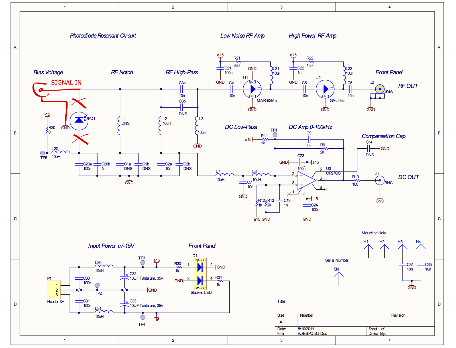
A quick estimate of the amount of distirtion in the BBPD amplifiers (MAR-6SM+ and GALI-6+):
The total amount of RF power in the attached spectrum is about +1 dBm (coming mostly from 4f1). Before the GALI-6+ in the BBPD, that's −11.2 dBm at the output of the MAR-6SM+.
The output-referred IP3 of the MAR-6SM+ is +18.1 dBm. Assuming the third-order distortion of the amplifier grows like the cube of the input power, this means the expected power of the third-order distortion is −11.2 dBm − 2×(18.1 dBm + 11.2 dBm) = −70 dBm out of MAR-6SM+. Then after the GALI-6+, the distorted power is −58 dBm.
[Koji, Rana]
The preamp chain of the BBPD was electrically tested. It turned out that intermodulation can explain the observed RF signals at 27MHz and 135MHz.
Method:
A spare BBPD at the 40m was used for this test.
The photodiode was removed from the BBPD circuitry and an SMA connector was soldered instead. (Attachment 1)
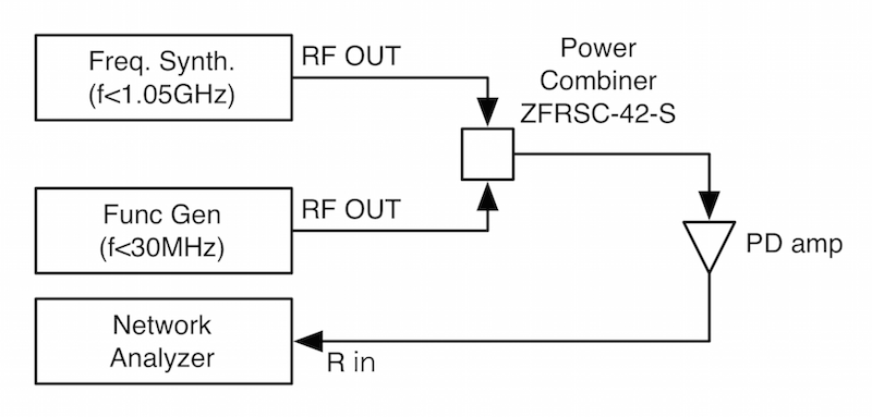
The measurement setup is depicted in Attachment 2.
The RF signals from two signal sources were combined with a power combiner and fed to the modified BBPD.
The output was connected to a network analyzer in order to monitor the output levels at each frequency.
Measurement 1:
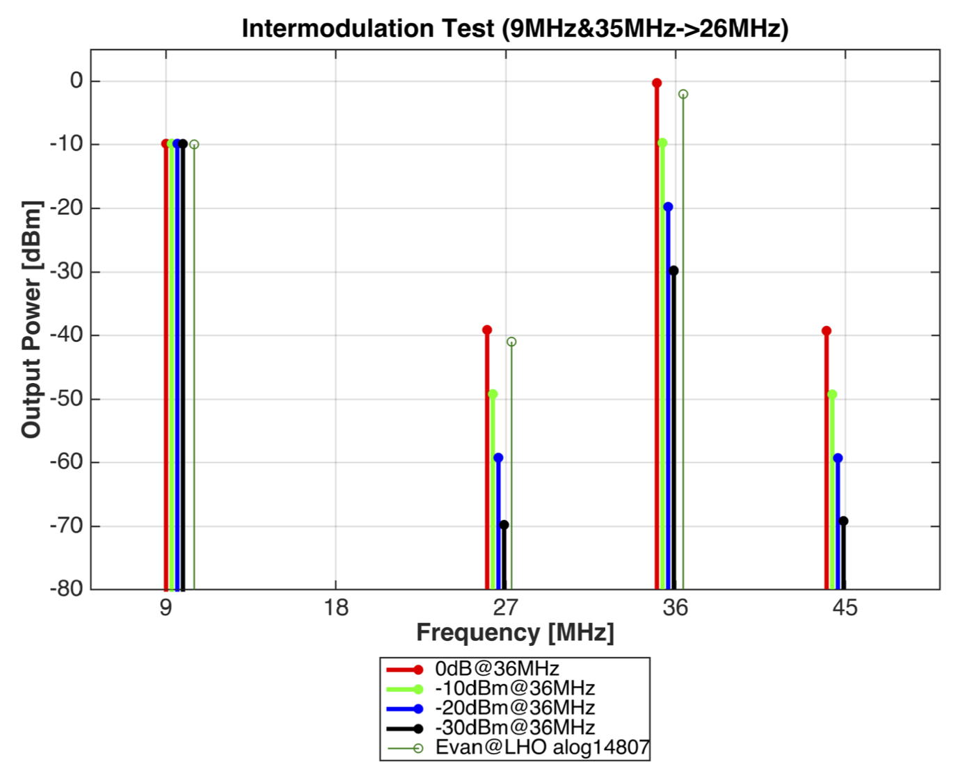
Firstly, Intermodulation produced from strong 9MHz and 35MHz components was tested.
WIth these two signals injected, our taget signals appear at 26MHz and 44MHz.
This way we can avoid the interference by the third harmonic distortion of the 9MHz signal.
The result is shown in Attachment 3. The 9MHz and 35MHz input levels were adjusted such that the output levels are -10dBm and 0dBm respectively.
These levels were obtained from the measurement in alog14807 (above).
It is clearly seen that symetric intermodulation appeared at 26MHz and 44MHz. The intermodulation level is linear to the level of the 35MHz signal.
In fact, -10dBm@9MHz and 0dBm@35MHz explain -40dBm@26MHz which Evan observed in the inlock spectra.
Measurement 2:
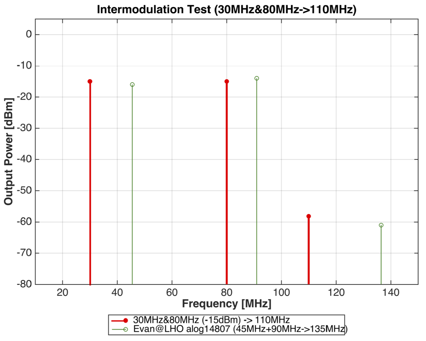
In the second measurement, it is tested if the intermodulation can produced enough amount of 135MHz signal.
Evan's measurement shows that both 45MHz and 90MHz have -15dBm.
From the lmitation of my setup, I had to use 30MHz and 80MHz to produce 110MHz, instead.
This indeed produced the 60dBm intermodulation, which is consistent with Evan's measurment.
Meaning of this measurement:
What happens if the intermodulation overwhelms the intrinsic signals at 27MHz and 135MHz?
- The intermodulation without fluctuation itself imposes unreasonable offsets in the 3f signals at DC.
- Power fluctuation of the sideband power in the 36MHz (f1-f2) or 91MHz (2xf2) causes unnecessary (=meaningless) signal to the 3f demodulated signals.
- The londitudinal IFO error signals in the 9MHz or 45MHz signals are imprinted to the 3f signals at a certain unknown demod phases,
and thus screw up the demod phase of 3f signals, as well as the immunity of them against the carrier audio sidebands.
Remedy:
- Lower the light power on the PD, if possible to maintain lock.
- Notch out/filter out unncesessary RF components before the BBPD preamps by adding components on the BBPD boards.
- Use resonant type photodetectors in stead of the broadband one to selectively amplify the desired lines.