jeffrey.kissel@LIGO.ORG - posted 20:46, Thursday 30 September 2021 - last comment - 15:54, Wednesday 03 November 2021(60082)
HPDS Controls Infrastructure (for ZM2, ZM4, and ZM5) Functional and Ready
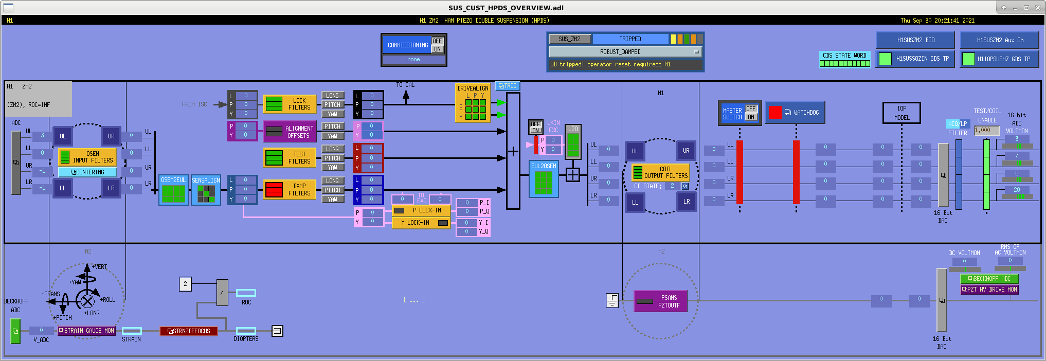
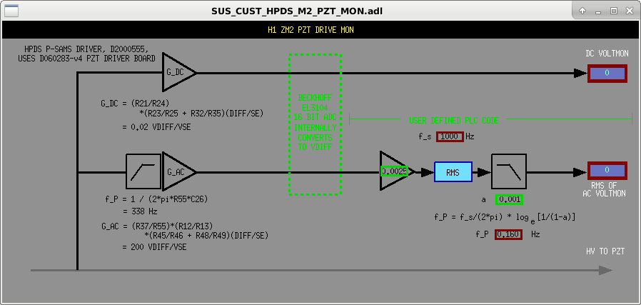
J. Kissel

Just in time (see LHO aLOG 60078), I've finished designing the MEDM screens for the HAM Piezo Double Suspensions (HPDSs), and filled out all the macro files, set up the EPICs parameters and filled out the foton files, and saved settings to the safe.snap of the SDF systems involved for ZM2, ZM4, and ZM5.

These new screens are now call-able from the sitemap as any normal suspension; ZM2 is under the SQZ IN menu, and ZM4 and ZM5 are in the SQZ OUT menu.

This is a resumption, continuation of, and completion of the work started in LHO aLOG 59696, and the comments there-in. The upper half of the HPDS OVERVIEW screen, controlling the M1 top mass stage is virtually identical to the ZM6 HSDS infrastructure. The lower stage brings to life the rudimentary fast front-end Simulink and Beckhoff control system that Daniel put together (see LHO aLOGs 59992 and 59993, respectively) that should get us through testing and commissioning this stage. Of course, I'd like to see this rudimentary infrastructure filled out more, so I include some wishful thinking on the screens, in hopes to guide future development.

I also note that this is the first SUS that's being driven and sensed by complete mish-mash of fast ADCs and DACs in the MER, a fast DAC in the CER, and some beckhoff ADCs for the PZT monitors and strain gauge readout. Quite a challenge for the MEDM macro system!

New screens have been committed to
    /opt/rtcds/userapps/release/sus/common/medm/hxds/
        SUS_CUST_HPDS_OVERVIEW.adl
        SUS_CUST_HPDS_M2_STRAINGAUGE.adl
        SUS_CUST_HPDS_M2_STRN2DEFOCUS.adl
        SUS_CUST_HPDS_M2_PSAMS_DRV.adl
        SUS_CUST_HPDS_M2_PZT_MON.adl
        SUS_CUST_HPDS_BIO_ALL.adl

the screenshots for which are shown in that order, using the ZM2 instantiation.
The macro files that support them have been updated,
    /opt/rtcds/userapps/release/sus/common/medm/
        suszm2_overview_macro.txt
        suszm4_overview_macro.txt
        suszm5_overview_macro.txt
such that, LLO only has to svn up these directories (and link them in the right way to their sitemap) to receive the goodness.

Everything should be ready to go for testing when Nidhi, Fred, and Rahul get to it!
Images attached to this report


Comments related to this report
J. Kissel, L. McCuller
I've now walked Lee through these screens, and he has the following redlines:
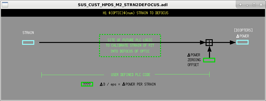
- The "DIOPTERS" imagined output is actually *change* in defocus in diopters. Thus, it doesn't make sense to convert this to ROC.
- Instead, there's a nominal radius of curvature that creates a nominal defocus lens, and the PZT pushes strain on the optic to create a change in the nominal defocus of the optic, creating a delta defocus. As such, it really only makes sense if the "ROC" readout is
ROC = 2 / (nominal ROC's defocus + delta defocus),
where "nominal ROC's defocus" is an EPICs record (informed by the design T2000101, or a measured value), and "delta defocus," dD, is the live channel converted from the strain gauge voltage.
- Also, we would love it if the live channel, dD was zero at the nominal radius of curvature (or defocus). As such, depending on the real system and the payload, and other offsets in the wheatstone bridge readout of the strain gauge may happen. So, we need an EPICs write, additive offset at each step along the way of the strain gauge readout calibration into dD (delta defocus): at the ADC voltage step, the strain step, and the defocus step. Not to say that we would use all of those offsets, but having them there at each step means that however one measures or frames the offset, one can stick it in at the right conceptual place.
- Finally, once we get all of these "make the signals meaningful" tweaks, let's add a slider on the offset for dD / diopters to make the actuation meaningful as well. This requires quite a good bit of understanding of all the complexities of PZT drives, strain gauges, bending of constrained optics under central force, but I think we'll get there, especially with superb characterization like that in LLO aLOG 57322.
In addition we brainstormed about the ideas for what he might imagine being in the " [ ... ] " section of the screen -- i.e. what might be the connective control system between the strain / defocus readback and the PZT drive voltage.
(1) We say out loud, that it's WAY too early to consider such a control scheme, but you might imagine -- say for the SQZ to IFO ZM4 / ZM5 path -- that there is an interferometric (bullseye) sensor measuring the mode matching between the SQZ path and the IFO OUT path, then you would have an "ISC INF" path that requested an adjusted change in diopters, dD, which then, via the readout of the strain gauge, drove the correct amount of PZT voltage to get there. And thus, you could get a loop that optimized the mode matching between the IFO and SQZ paths. Again -- WAYYYY to early to think about such things, but the idea is there. I won't build this into the MEDM screen.
(2) One might also imagine that if you want to keep a fixed value, offset from nominal, for the change in defocus, dD (i.e. the strain gauge readout), then you could wrap a loop around dD, driving the PZT voltage just to keep the strain/defocus constantly at that value. Now, what would be the noise sources of that loop that would make that be noisy or drift? Who knows, and probably the answer is "there aren't any," other than slow decay in the gain of the PZT driver or something. But, it's another loop one might imagine.
For now, though, we agree that we *don't* imagine we need to make further changes to reflect any of these (made up?) dreams. Other than the offset, the correction to the imagined math to get the "ROC" value to be meaningful, and the slider control of dD, we shouldn't need *anything* more sophisticated than a "good ole EPICs servo" where we slowly make "this EPICs record" to "this number" using "this EPICs channel to drive it there" at a "way slower than EPICs" UGF.
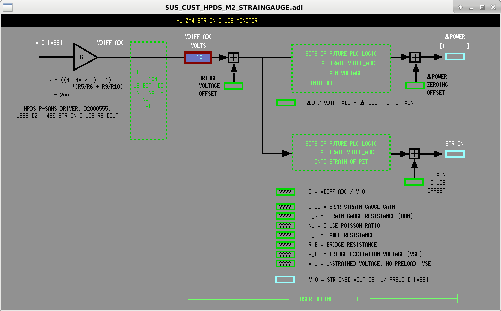
I've implemented the MEDM screen modifications to include the redlines from the comment above, LHO aLOG 60102. See attached screenshots of updates. Note, since I only changed the strain gauge side of the M2 stage, the second attachment is a zoom in on that bottom left corner where all the action is.

Of course, none of this code exists in beckhoff yet, but hopefully, since the PLC is "just code," visualizing the design intent like this will help make the coding easier and make the code more legible.
Images attached to this comment

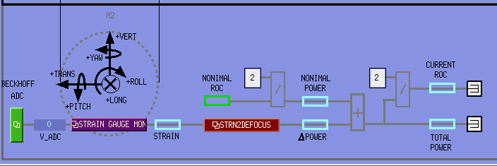
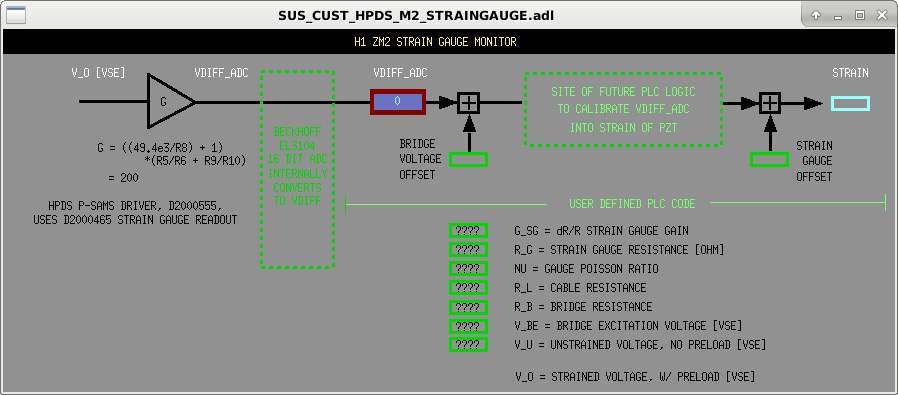
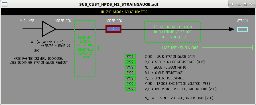
A. Brooks, M. Kasprzack, J. Kissel, L. McCuller

After talking through the imagined function of strain gauge readout, and looking at the very exciting / successful raw data that Georgia, Lee, and Wen gathered last week 60411, we think it makes more sense to structure the strain gauge calibration in a way that the attached screenshot of the collection of 3rd-round modified MEDM screens.

Namely, the calibration of the ADC voltage for the strain gauge in to strain and diopters of optical power should be parallel paths, rather than series paths. Why? Because the calibration of strain gauge voltage to (milli)diopters of change in optical power or defocus is a trivial gain, of which we already have excellent measured results. The calibration into strain is a quadratic relation to the voltage, and depends on a complicated formula with a lot of parameters that range from relatively uncertain to unknown/lost. So, we hope to make the code available for some future awesome person to easily create a channel calibrated into strain, but it's not needed, and much harder than the direct conversion from differential voltage at the ADC [V] to change in optical power [mD] that we already have in hand.

As such, there's no longer two blocks, STRAIN GAUGE MON and STRAIN2DEFOCUS, in series, there's just the one block, STRAIN GAUGE, which has (the *future* readbacks and inputs of) the conversion to both strain and change in optical power.

Again, none of this beckhoff code or channels exists, but we draw the user interface first to more easily inform what needs to be written in code.
Images attached to this comment