cheryl.vorvick@LIGO.ORG - posted 20:46, Friday 15 October 2021 (60292)
PSL measurements and prep for Faraday alignment
Today on the PSL we took beam measurements, and started the modifications for revisiting the Faraday alignment.
Measurements:
- changes to L1 and L2 from mode matching to the first amplifier
- NPRO to L1: this is measured with zero at the front of the body of the NPRO. From the front of the NPRO to M01 = 6.5cm, and M01 to L1 = 2.7cm, combining those gives an NPRO to L1 distance of 92mm, L1's previous position from the NPRO was 98mm.
- L1 moved = -6mm.
- M03 to L2: M03 is at 1.414m from the NRPO, L2 was at -35mm from M03, at 1.379m, before the move, and now L2 is -50mm from M03, at 1.364m, so L2 moved towards the NPRO by 15mm total.
- L2 moved = -15mm
- the numbers for L2 don't take into account the faraday's DKDP
- NPRO to L1: this is measured with zero at the front of the body of the NPRO. From the front of the NPRO to M01 = 6.5cm, and M01 to L1 = 2.7cm, combining those gives an NPRO to L1 distance of 92mm, L1's previous position from the NPRO was 98mm.
- the NPRO beam was measured to have wiast sizes of 170um, and waist positions at -106mm, which roughly matches an earlier measurement
- downstream of the faraday, the beam has shifted in yaw, presumably when we adjusted L1 pitch and yaw, and the beam is now miscentered in yaw on L2
- power through the Faraday:
- measured at 1.8W from the NPRO: before the faraday = 1.59W, after the faraday = 1.406W, 88% through
- measured at 110mW from the NPRO: before the faraday = 98mW, after the faraday = 109mW, 90% through
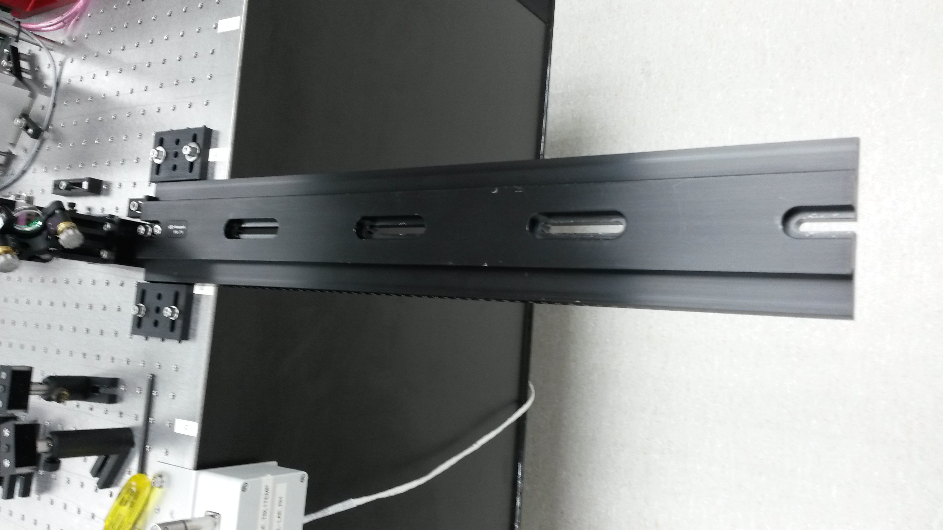
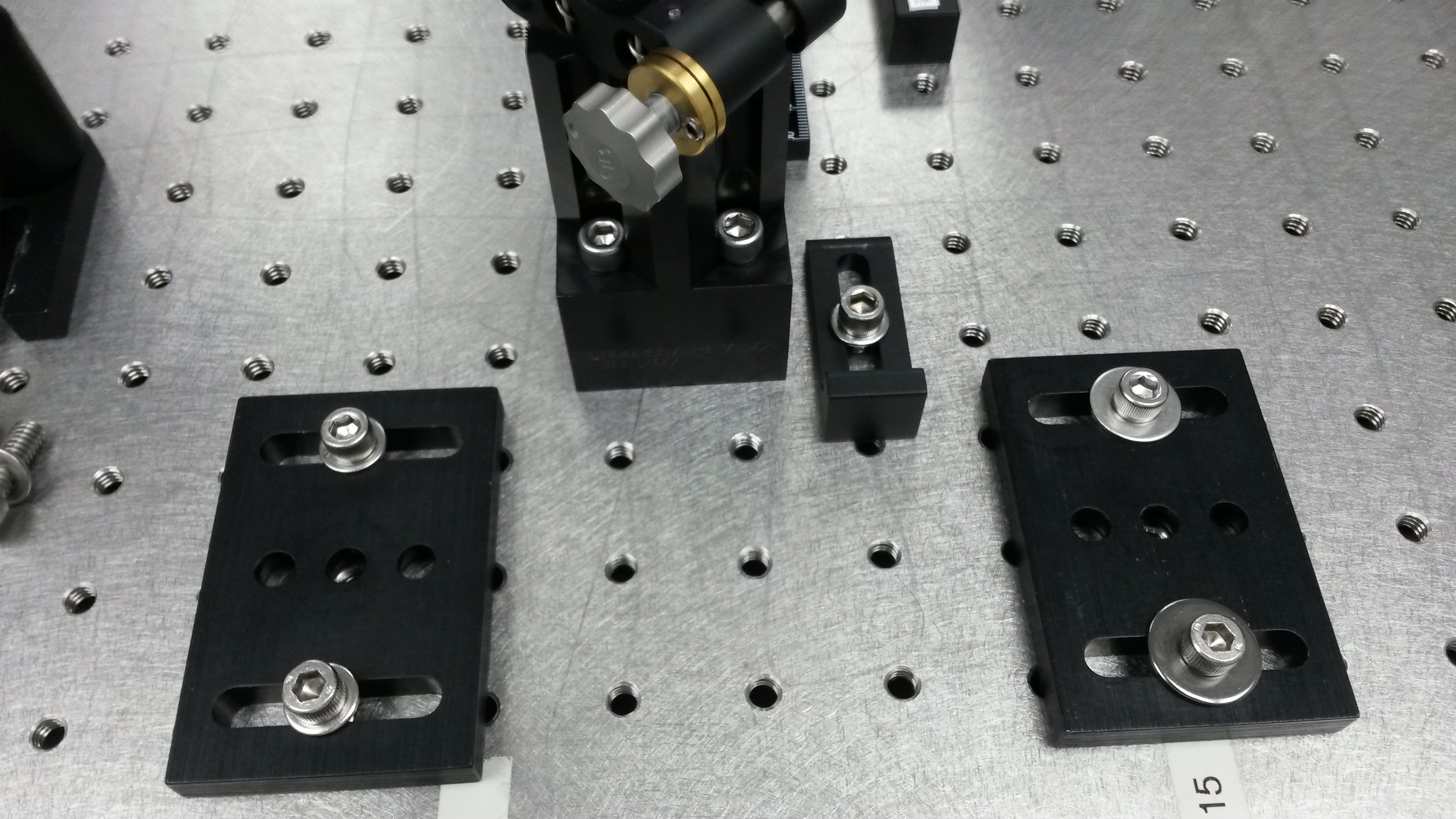
- the rail that was installed to measure the beam profile after M03 is removed from the table, but blocks remain on the table to reinstall and return to the previous position. For reference:
- from M03 to Neo1 (the first amplifier) is 450mm
- when the WinCam sensor is at 35.3cm on the rail, it's at the position of the Neo1 input window
- 450mm to Neo1 = WinCam senosr at 35.3cm on the rail
- beam waist is at 29.3cm on the rail
- prep for faraday measurements:
- the rejected beam from the first polarizing beam cube had it's razor blade dump swapped out for a 70W beam dump
- the first HWP, before the beam cube, was roatated to reduce the power in the main beam, dumping most of it into the newly installed 70W beam dump
- after rotating the HWP the power in the main beam path is ~110mW
- this configuration is how we left the table for the weekend
Attached:
- pictures 1-2: rail used on M03 transmitted beam
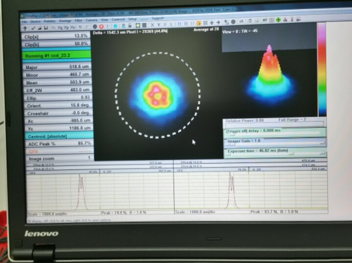
- picture 3: the beam as it enters the first amplifier (Neo1 input window, 35.3cm on the rail)
- picture 4: higher order modes (seen only in beam scan 5cm+ beyond Neo1 input window, 40cm+ on the rail)
- Cheryl, Varun
Images attached to this report