TITLE: 07/03 Day Shift: 1430-2330 UTC (0730-1630 PST), all times posted in UTC
STATE of H1: Lock Acquisition
INCOMING OPERATOR: Ryan C
SHIFT SUMMARY:
Today was Thursday Commissioning from 8am-1230pm, and had a locked H1 for 1hr45min of the commissioning time and had a few commissioning tasks squeezed in this time.
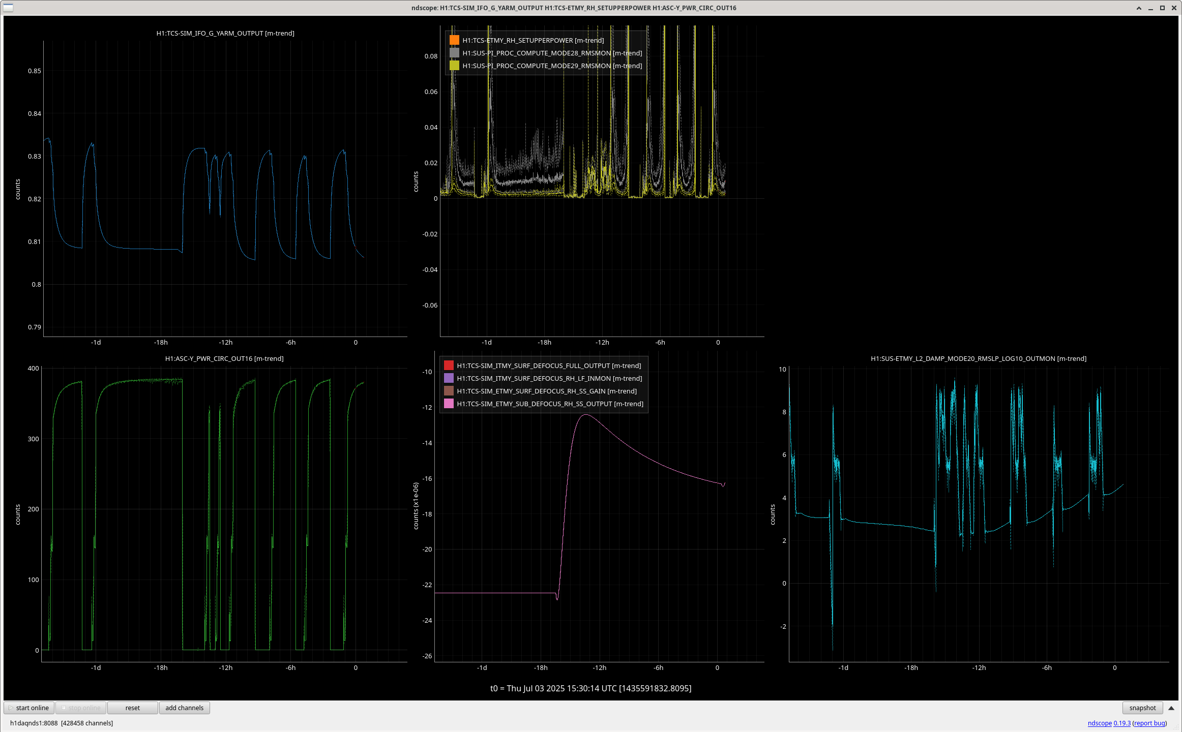
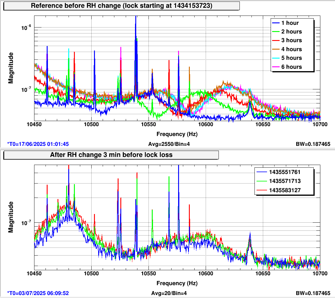
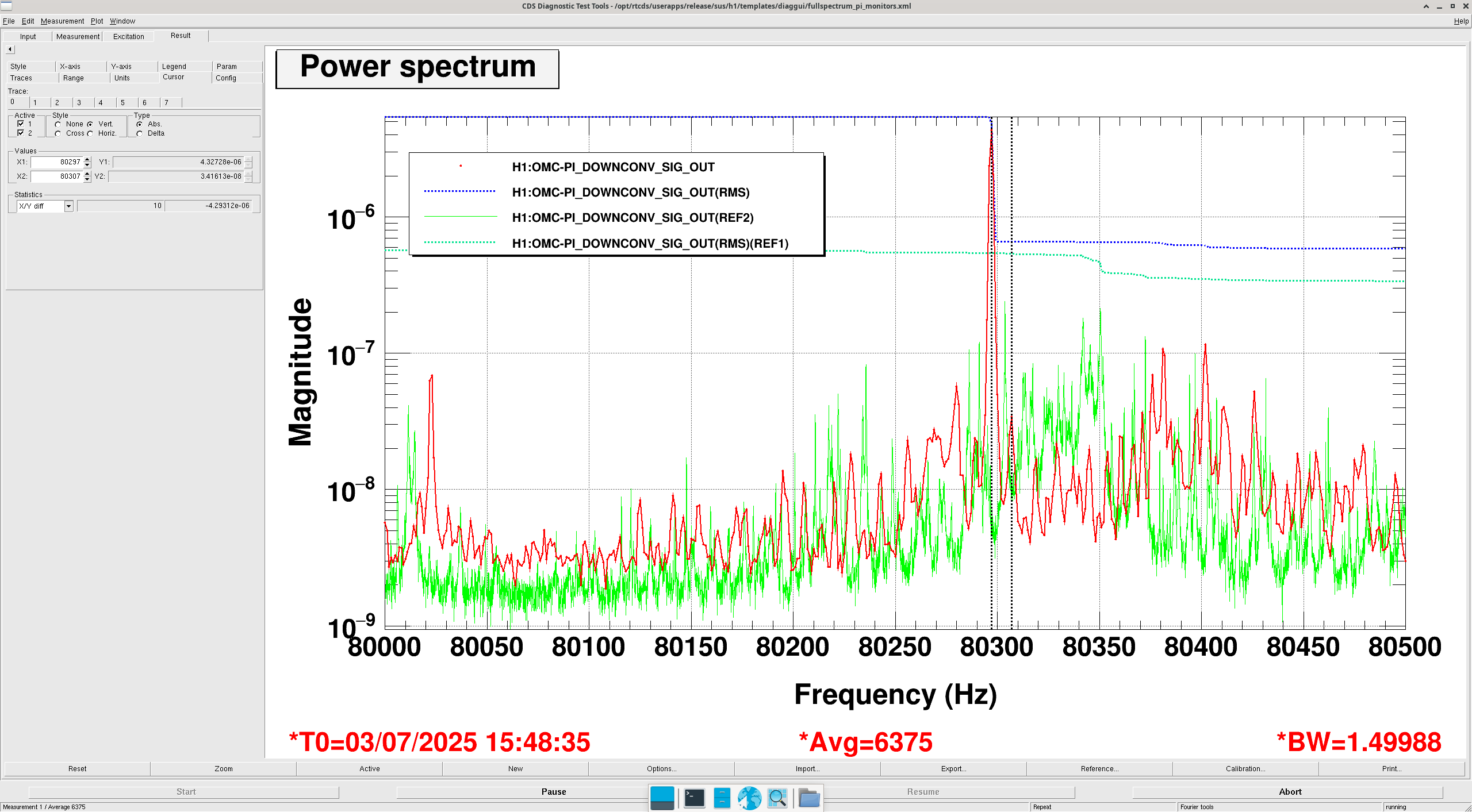
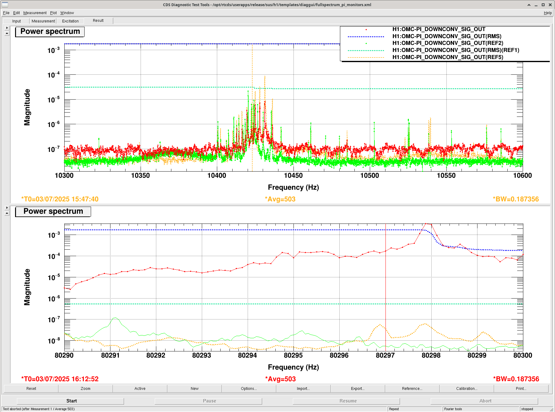
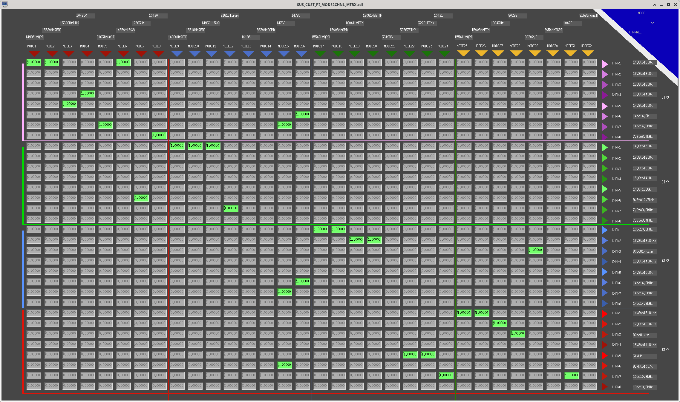
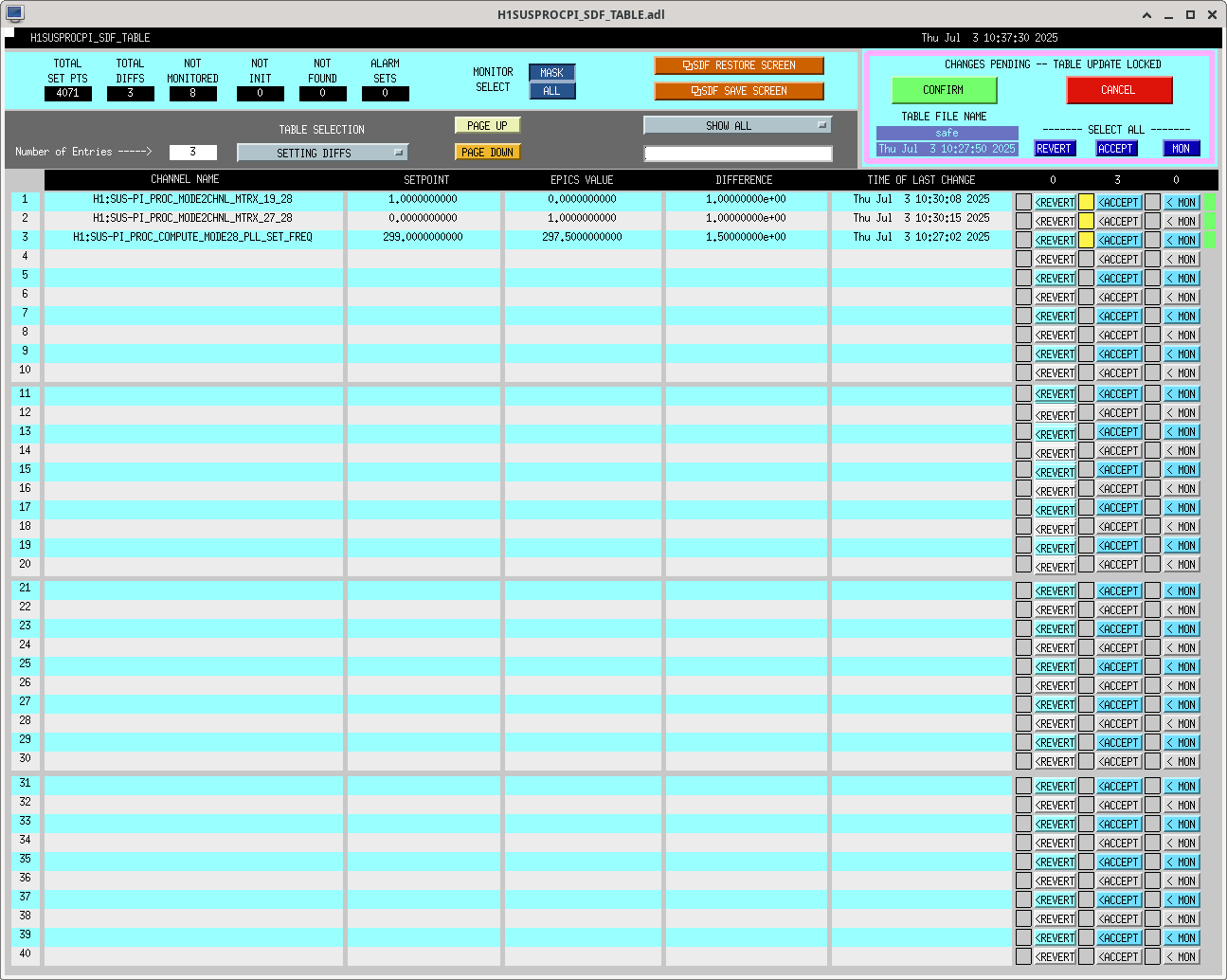
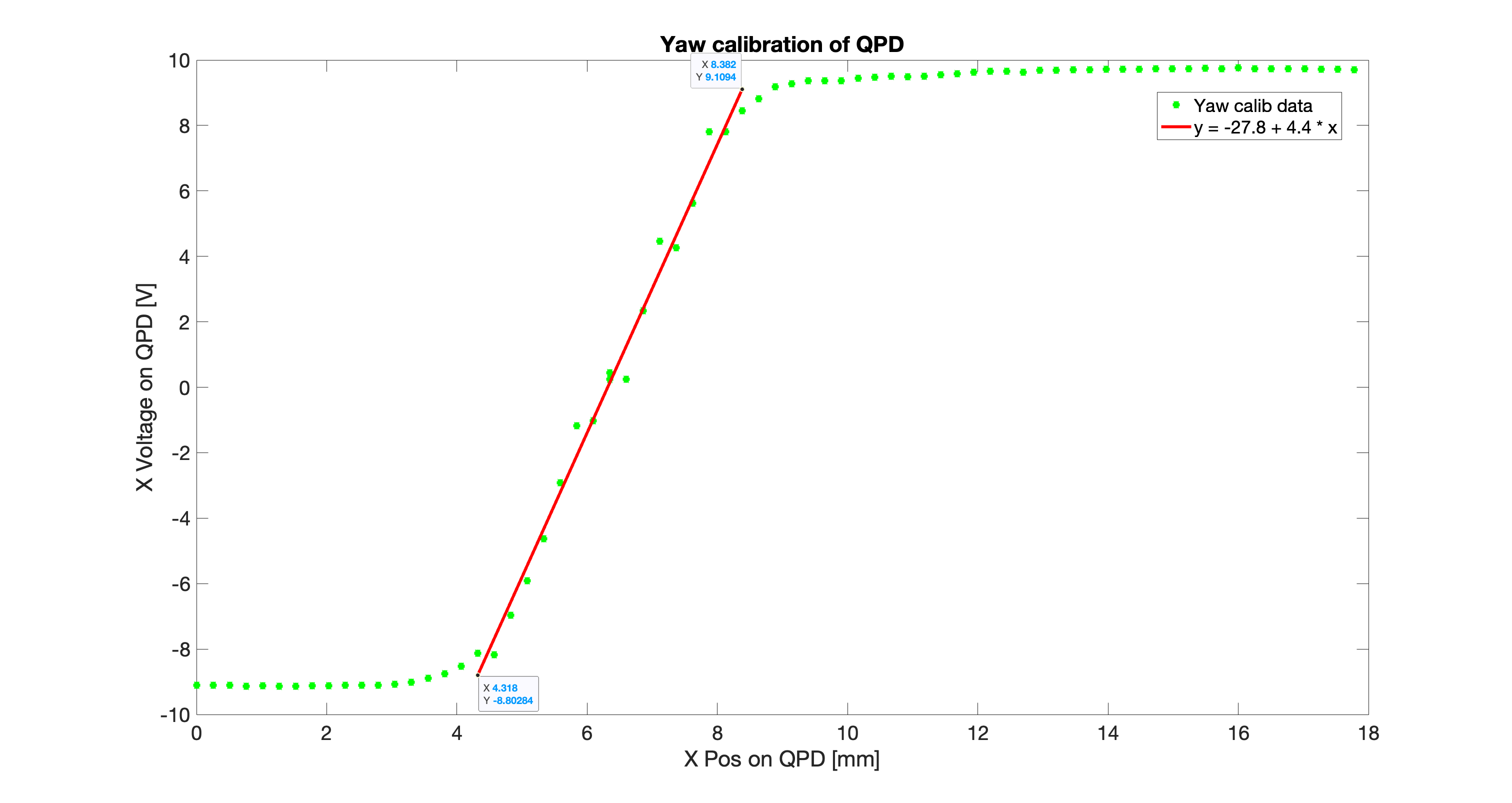
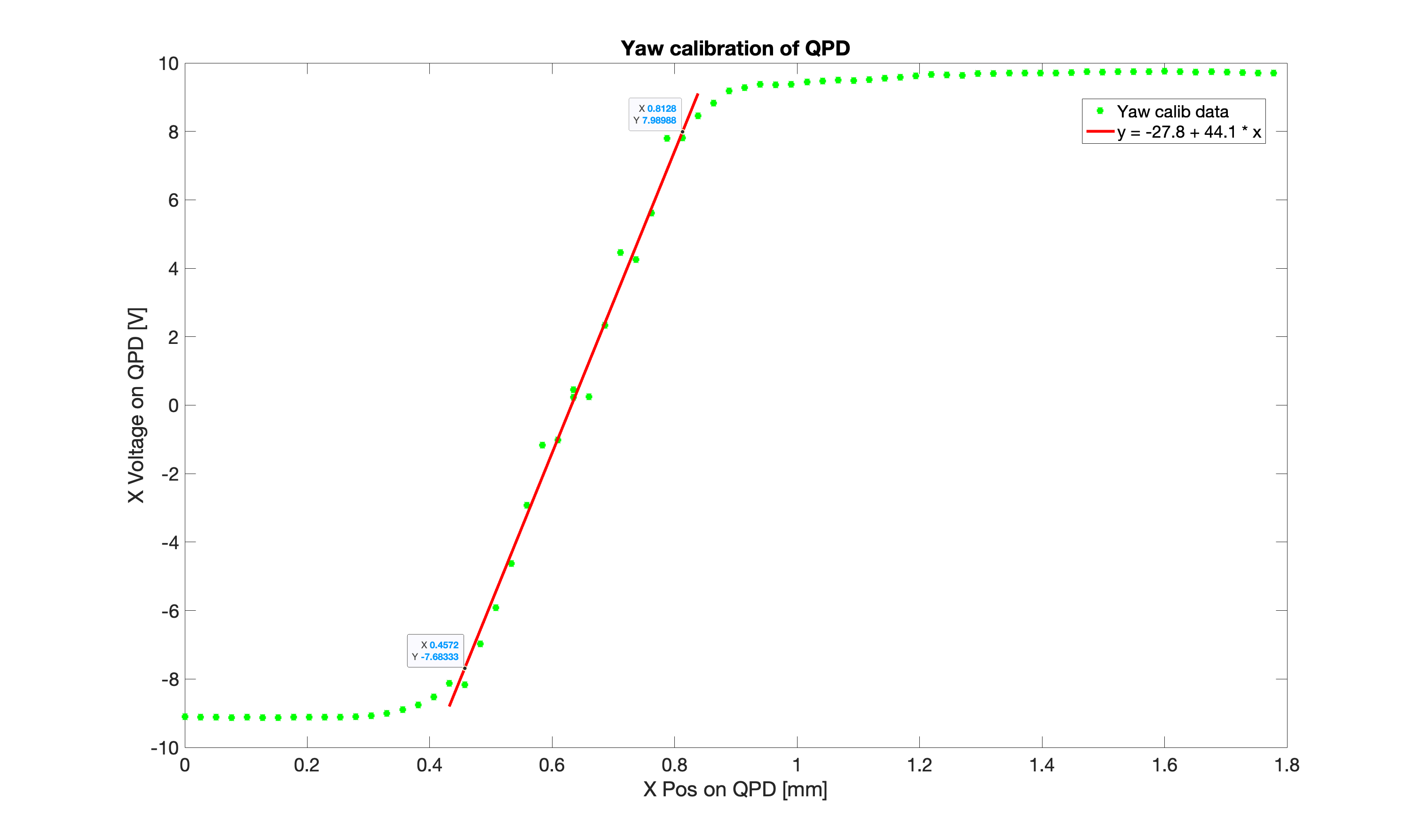
H1 continues to be plagued by ringing up PI Modes that cause locklosses. So, today different settings continued to be tried (latest & current ETMy Ring Heater setting is 1.5 W for the upper and lower). But for some of these changes, we have had to try different violin mode settings (for ETMy Mode 20)---see this alog85527.
Also, the input pointing which was lost due to the HAM2 SEI Power supply swap on Maintenance Day, was reverted back by Elenna (alog85533).
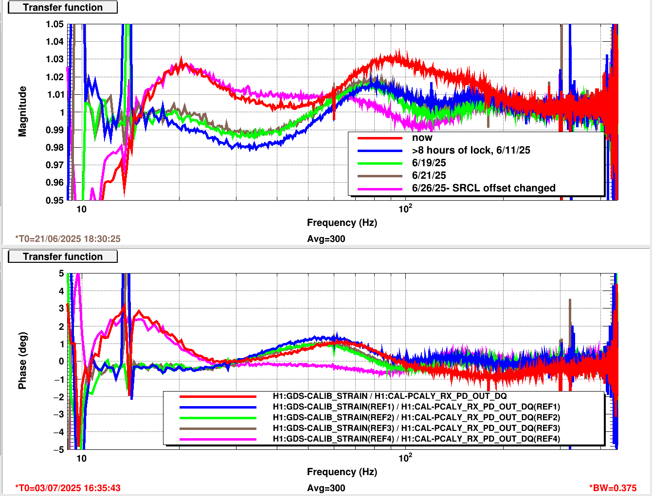
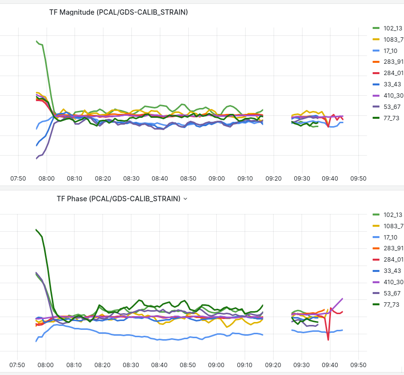
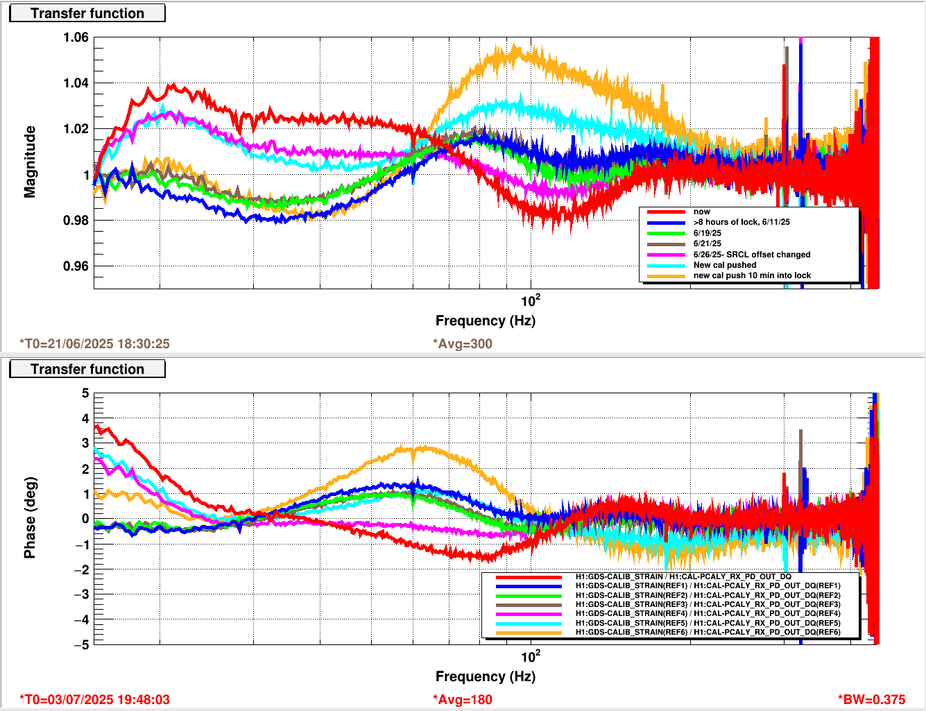
Did not get to run the calibration suite today, so hope to do this after H1 gets to 3hrs during RyanC's shift tonight.
LOG:
- H1 was locking at beginning of shift (powering to 25W)
- 1458 OBSERVING (w/ Max Power reached at 1447)
- 1511 COMMISSIONING Begins
- 1511 Robert's tasks: (1) Compensation plate scans (finding a new place now that the annulus pumps are off), and (2) More evaluation measurements for Before/After the recent O4-Break.
- 1557 ETMy Ring Heater lowered to 0.9
- ~1725 ETMy Ring Heater lowered to 0.6
- 1619 ETMy Violin Mode gain changed from -1 to 1 (it was seen ringing up)
- 1635 Calibration (broadband) started, but I accidentally CTRL-C-ed out of the terminal I was running it on (I had tried to "copy" text.). The CTRL C did not stop the EY PCal excitation. I needed to get help from Jonathan/Eric to finally get rid of the excitation.
- 1645 Lockloss (PI 28/29 were ringing up and also trying to get out of the calibration at the time of lockloss).
- 1728 Initial Alignment started, but stopped after INPUT ALIGN to have
- Then continue with the Alignment again starting at INPUT ALIGN
- 1717 ISS pd work in optics lab (rahul, jennie)
- 1740 out for calculations & back before lunch maybe
- 2142-2230 Heading back in the lab.
- 1806-1836 Beckhoff Machine power cycle in Mechanical Room (patrick)
- 18231905 Running Cables for injections (robert)
- 1852-1908 Matt & parents took peek in LVEA
- 1857 NLN
- 1952 PI28/29 Lockloss
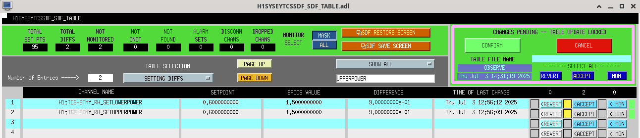
- ETMy Ring Heater increased to 1.5 (from 0.6).
- 1910 Running new Broadband Calibration (attempt #2---and I won't try to "COPY" anything!)
- 1947Running for 3rd time....
- 1952 LOCKLOSS due to PI 28/29
- 2025 Initial Alignment run since DRMI & PRMI didn't catch, and it was close to 30min since the lockloss.
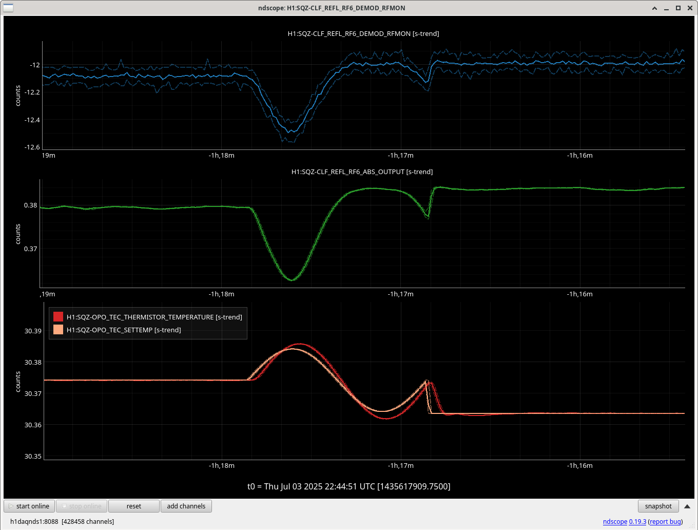
- 2120 NDS0 crashed----Erik restarted and we restarted FOM ndscopes.
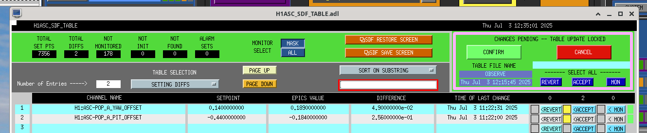
- 2135 Back to OBSERVING. To get here, had to:
- Accept the SDF Diffs for the newest ETMy Ring Heater laser power (it is now at 1.5 for upper and lower)
- And for the Squeezer, the SQZ_ANG_ADJUST had to be taken to DOWN to get the SQZ MANAGER to its nominal state.
- ETMy MOD20 started to ring up again and this is with the new ETMy Ring Heater laser power of +1.5
- +30, -1.0---ring up
- +30, +1.0---ring up
- +60, +1.0---Damped it down & worked.
- 2259 -2301Dropped from Observing for SQZ changes (Sheila).


