Chris, Alexa, Pablo, Keita, Sheila
This is a late alog of work done thursday afternoon and friday morning. The short summary is that we think the beam quality problem we are having on WFS B is caused by the Faraday used to reject the reflected beam, we don't think we have clipping between our on table PZTs and the TMS QPDs, but might have some in the path from the PZTs to the WFS.
First we used the technique Keita described in alog 11280 to look for evidence of clipping. When we dither the PZTs we see 30-40dB more resoponse in the QPD PIT or YAW than in NSUM, but for the WFS we the difference is more like 20-30dB, which suggested to us that we could have clipping in the WFS path itself (we had already checked on the table all the optics in this path, and didn't see anything that looked bad, so we suspected the Faraday.)
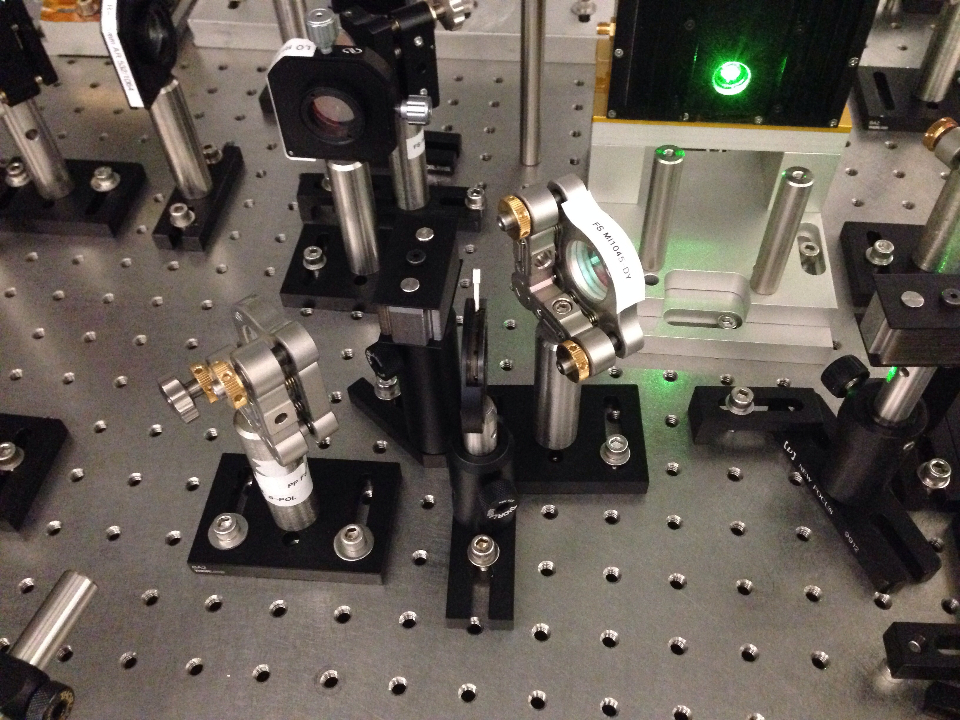
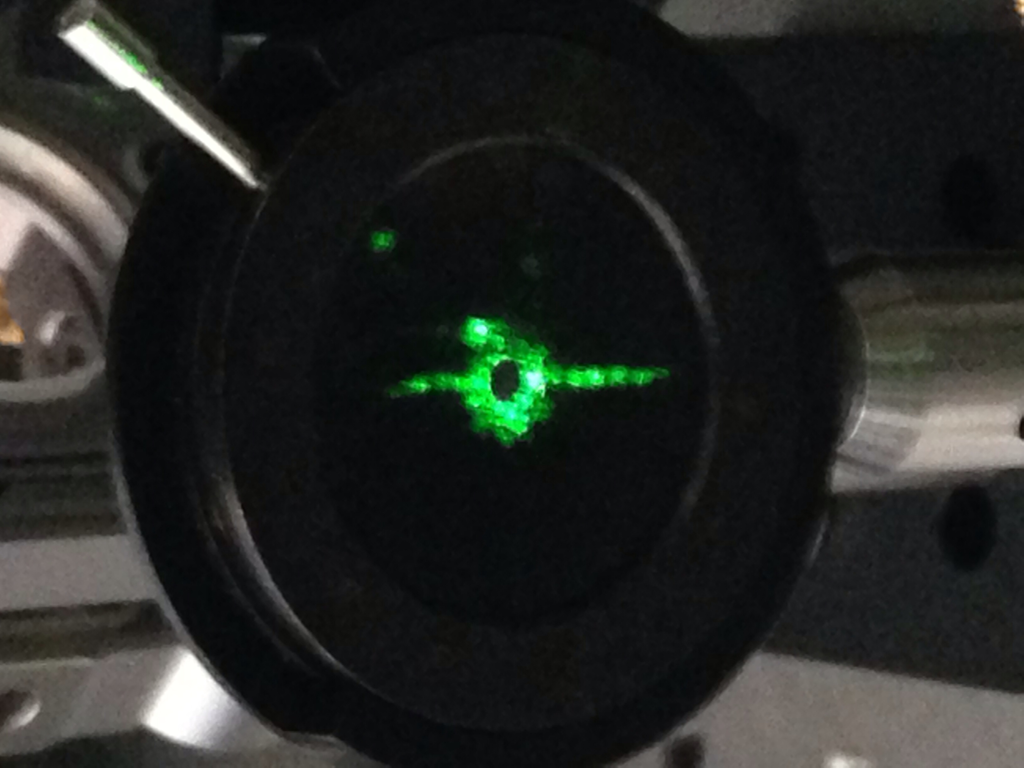
On friday morning Pablo and I went out to the end station and set up the beam profiler again. (images attached) We started by measuing the beam in the path to WFS B (this has been the troublesome one for beam quality) at a point upstream of where we have been, and see that the beam quality is also bad there. We moved the nanoscan to approximately the position of WFS B, and tried moving the first optic after the Faraday to see if this has the same impact on the beam quality that we have seen from moving TMS QPD servo offsets (see alog 11072), shown in the second page of the attachment. It didn't so we concluded that the problem must be upstream of that optic. We then tried moving the Faraday using the new 4 axis mount, and that did have a similar impact as moving the TMS QPD offsets. This may mean that the problem is in the Faraday. We tried several iterations of moving the Faraday in pitch, but didn't really suceed in improving the beam quality much and actually made it worse in the horizontal direction, and made the beam quality going into the chamber worse. We set the Faraday angle to restore a nice guassian profile for he beam going into the chamber.
We then tried putting an iris into the WFS path just after the slipt from the path for the LSC diode (photos will be attached soon.) This dramatically improved the beam quality on WFS B, but didn't change th situation on WFS A. We set the iris to be slightly more open than the position that gave us the best guassian fit to our beam profile, to allow for some alingment drifts. We saw that the iris really dosen't impact the beam quality on WFS A.
So as we left things, we had good beam quality on WFS B and the beam going into the chamber, and the same so so quality that we have had on WFS A since we reworked the path (alog 11074).

- Measure the beam profile in Hartman path. Is it really Faraday?
- Place a flat high reflector as a retro reflector right after Faraday, and measure the beam in WFS path. Is it really Faraday?
- Is it really Faraday?