jeffrey.kissel@LIGO.ORG - posted 11:58, Monday 22 August 2011 (1264)
OSEM Watchdog now Band-Limited
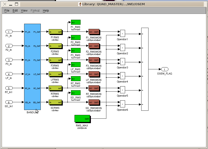
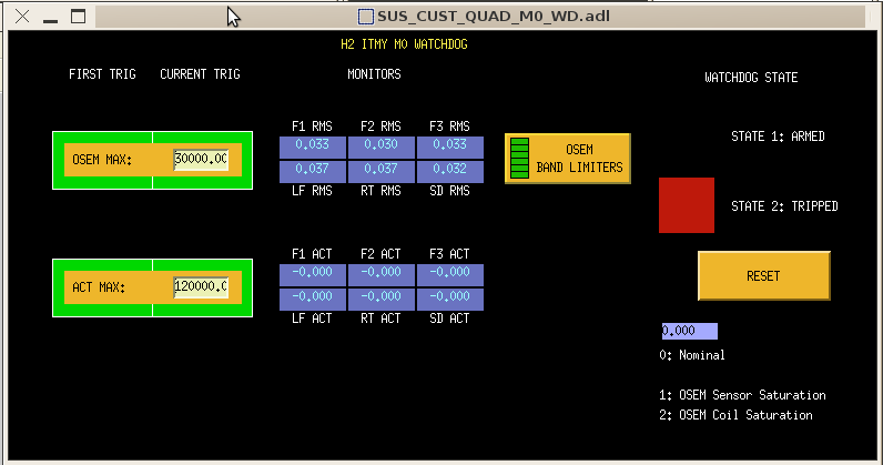
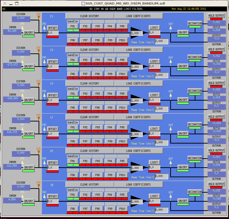
J. Kissel, K. Arai, R. Lane, J. Garcia, R. Mittleman, B. Shapiro

In eLIGO, the SUS watchdog had been cobbled together as its own CDS block quickly using iLIGO watchdogs as a model, and was never properly understood (at least by me), nor well documented. In the switch over to aLIGO RCG, I had made an attempt to simplify the SUS watchdog by taking advantage of the more simple CDS RMS filter block (see entry 1265 for details).

However, I had naively used the block to take the RMS of the OSEM raw input signals and called it good, because I had assumed that the time constant of the averaging filter also defined the frequency response of what signal was being watched (as though the RMS filter was a linear block). However, after some experience using this simple watchdog, and discussions with Brett, Rich, and Koji, they've [reminded / convinced / taught] me that this isn't what we want to watch at all.

Hence, we've installed band-limiting filters between the raw OSEM signals and the RMS filter. The frequency response of this filter is attached, but can be described by the following bit of design code:

bandLimPoles = [0.1 10 10];
bandLimZeros = [0];
bandLimFilter.c = zpk(bandLimZeros,-2*pi*bandLimPoles,1);
gain = abs(squeeze(freqresp(bandLimFilter.c,2*pi*1)));
bandLimFilter.c = bandLimFilter.c / gain;

The motivation behind this shaping of the signal is as follows:
- The frequency band in which the suspensions are moving the most is between 0.1 Hz and 10 Hz, given that all resonances for all degrees of freedom are confined to this band.
- Above 10 Hz, the OSEM signal is dominated by sensor noise, and hence is not useful as a watchdog signal.
- Even if there were useful signals above 10 Hz, (a) the coils and coil drivers do not have the strength to push the suspension around, (b) the suspension's response to actuation is rolling off drastically anyways, and (c) given that this frequency band is above the fundamental resonances of the suspension, if the suspension point is driven at 10Hz and above, the significant passive isolation should provide sufficient protection.
- The OSEM signal must be AC coupled, or else the RMS is dominated by the DC offset of the OSEM which is not useful as a watchdog signal. We are interested in the position amplitude RMS around the resonances, such that we can catch large, on-resonance, amplitude motion that would drive the suspension into its stops, In other words the response of the signal fed into the RMS filter should be flat, since OSEMs are inherently a position sensor. That means there must be *some* pole frequency where we switch from an AC coupled velocity RMS to flat position RMS. If this pole frequency is too low, the position RMS of the resonaces will be washed out by the inherently large low-frequency motion. Hence, as a first, reasonable guess, we've chosen 0.1 Hz -- just below the lowest longitudinal resonance.
- As mentioned in aLOG 1265, the step response of the RMS filter is roughly 7 seconds. This is another goldy-locks problem, in that if the step response is too long or too short then one loses functionality. We know 100 seconds is too long, 1 second is too short. Given that we're "stuck" with 7 seconds we figured it would suffice for now.

In summary, the exact shape (where to put the poles and zeros) of the signal to be RMS'd is quantitatively arbitrary, but the response now has the right qualitative shape. Poles at 0.1 and 10 Hz can be tweeked later if necessary, and given increased functionality in the RMS block we could adjust the time constant. The watchdog now has the right functionality for the system at hand .

I also attach pictures of the infrastructure
- osemwatchdogsimulink.png: screenshot of the signal flow of an OSEM sensor flag generator in the QUAD_MASTER.mdl simulink diagram (found in the QUAD//WD/OSEM/ subsystem, isoStage=[M0, R0, L1, L2])
- osemwatchdogmedm.png: screen shot of a given stage's watchdog MEDM screen. The OSEM BAND LIMITERS bank is button that takes you to
- osembandlimmedm.png: the filter banks where the band limiters are defined in FM1.

The last attachment is a spectra of an L1 OSEM comparing the signal before and after the bandlimiting filter, just to prove it's functionality. The suspension is locked and not plugged in, so the actual signal is rather meaningless. Once we get a functional suspension, I'll put the effort into making a calibrated plot, containing more useful information,
Images attached to this report
Non-image files attached to this report
