jeffrey.kissel@LIGO.ORG - posted 18:15, Wednesday 06 August 2014 (13250)
UWash Tiltmeter installation: making good progress
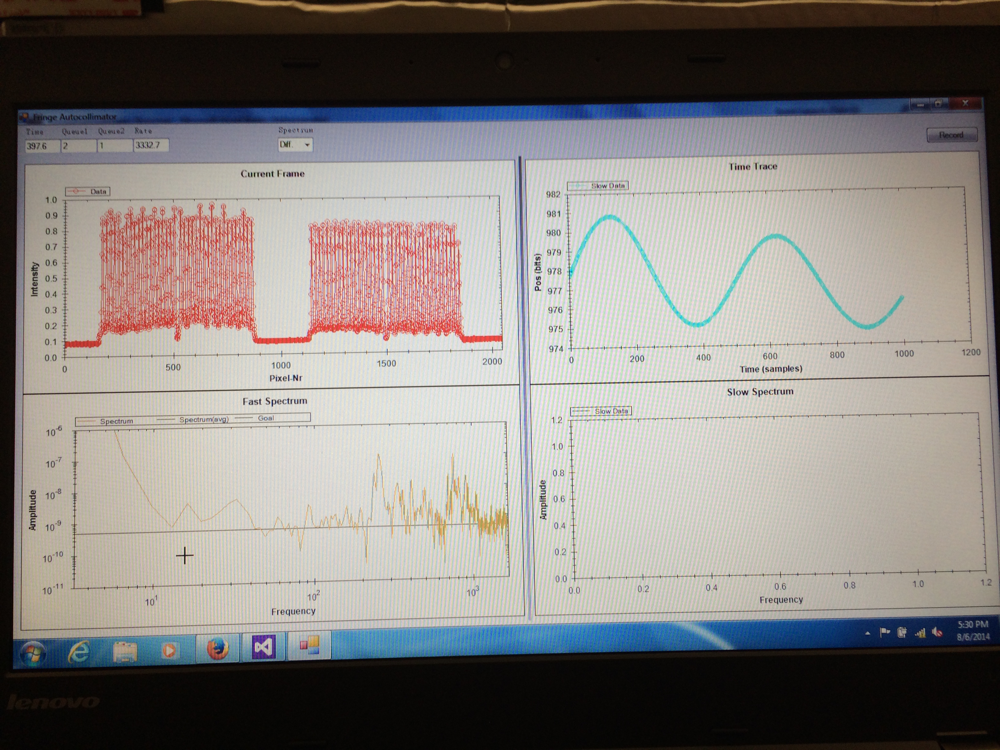
Jeff K., Krishna V., Erik S.

We managed to reduce the frequency to about 6 mHz. We then attached the left arm of the vacuum can. The heat-shield cross-links were then connected, the reference beam-splitter was installed and we did a rough alignment of the optics. The top flange was then put in place and we bolted the autocollimator on and turned on the LED. With some foil-shims under the autocollimator, the alignment was good enough to get clean images of both the reference beam-splitter and the balance-mirror. After a few attempts of moving the adjustment rod very carefully, we managed to get the balance-mirror in range of the autocollimator.

We then enclosed the tiltmeter in the foam-box and started the data-taking program on the laptop. The next step will be to measure the tilt transfer function to measure the distance between the center of mass (COM) and the pivot. We will then adjust masses on the balance to minimize this distance.

We're already measuring sub-nanoradian precision.... at 10 [Hz] ;-). See attached read-out display. On the upper right display is the difference between the reference mirror and balance mirror position as measured by the autocollimator (left and right image pattern on the upper left panel, respectively), where 1 [pixel bit] = 3.5 [urad]. You can see the spot images that the CCD is sampling on the first images of the "Day3b.pdf". The ASD in the bottom left corner shows the measured tilt as a function frequency.
Images attached to this report
Non-image files attached to this report
