Stefan, Evan
This is an analysis that Daniel suggested a while ago.
When we increase the interferometer power from 3 W to 24 W, we increase the common-mode radiation force on the test masses. Since the suspensions are compliant, this produces an extra displacement in the test masses along the beamline relative to their suspension points. The CARM loop senses this common-mode displacement and compensates by applying a slow control voltage to the IMC VCO. This control voltage is offloaded to the UIMs of the end station suspensions, and then subsequently to the endstation HEPIs, thereby moving the suspension points of the ETMs forward so as to cancel the radiation-induced displacement. Therefore, an appropriately calibrated HEPI tidal signal can be used to estimate the amount of power circulating in the arms.
We looked at a data stretch from 2015-08-07, when we had been sitting at 3 W for a while and then powered up cleanly to 24 W, and found the following:
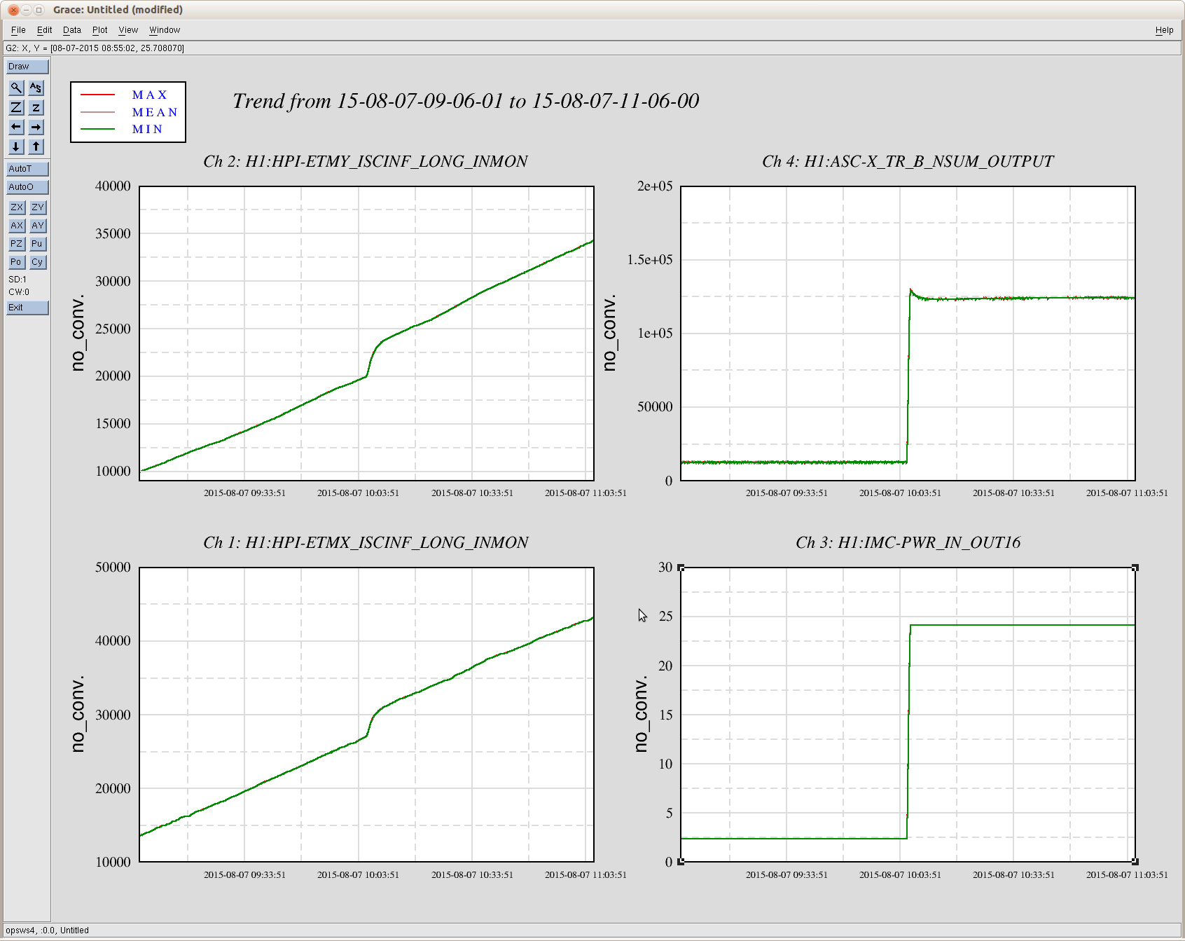
- The HEPI tidal signals show a nice, linear trend for the hour preceding and the hour following the power-up [first attachment].
- By fitting the linear trend [second attachment] and subtracting it off [third attachment], we can get an estimate of the HEPI displacement due to the radiation pressure alone. The displacements are 2.9 µm each for X and Y.
- During power up, the change in the force on the test mass due to the change in radiation pressure is ΔF = 2 ΔP / c. The dc compliance of each test mass is H = Δd/ΔF = 2.6×10⁻³ m/N, where Δd is the change in displacement of the end-station HEPI. Therefore, the power change is given by ΔP = c Δd / (4 H) [there is an extra factor of two here because there are two suspended masses per arm]. From this, the power change per arm is 85 kW.
- From the IMC input PD we know that the power ratio before and after powering up is P2/P1 = 10.3. This can be combined with the above power change to arrive at an absolute number for the circulating power: 94 kW.
On the other hand, when we make a similar estimate from the end-station QPDs, we have something like 24 W × 0.88 × 1/2 × 40 W/W × 283 W/W = 120 kW. [The factor of 0.88 is the modecleaner transmission.]
The calibration of the HEPI tidal signals into nanometers is sort of loose [to within 10%?], according to Hugh. Similarly, there is some spread in the power inferred from the endstation QPDs, which gives an uncertainty that is also on the order of 10%. With a more precise HEPI calibration, perhaps we could use this method to better constrain the optical calibration.


Hugh, Richard, and I had a discussion about the precision of the HEPI calibration, and in the end Richard suggested to just measure the calibration in some locked interferometer configuration (whereby we could read out some calibrated control signal).
I had a go at this by locking ALS DIFF (with IMC F offloading off) and driving HEPI at 200 mHz, with the goal of calibrating HEPI against the PLL. I got an OK measurement by driving 100 nm pk for 8 minutes or so, but then Jim and Hugh pointed out that the ISI was already suppressing some of the HEPI drive, so the measurement probably had significant systematic error. Additionally, Daniel was skeptical that one could cleanly separate length and angle changes on the test mass (both of which can contribute to the sensed CARM displacement).
Jim, Dan, and I thought a bit about this, and (to make a long story short) we forwent HEPI calibration entirely. Instead, we decided to lock the interferometer at 2.2 W, turn off the offloading of the UIMs to the HEPIs, and then power up. The dc portion of the CARM control signal should then accumulate on the UIMs. Since the calibration group already produces estimates of the dc UIM calibration for EY (the ER7 estimate was 5.1×10⁻¹¹ m/ct), we therefore already have a calibrated readout of the displacement induced by the circulating power (again neglecting angle effects). I don't think the calibration group produces similar estimates for the EX UIM.
This power-up happened around 2015-09-03 09:56:30, from 2.2 W to 22.4 W. I did a linear fit of the UIM drive before and after the power up (see attached). The initial/final slopes are 5.32 nm/s and 5.06 nm/s, so there is some error here in determining the amount of radiation-induced drive (about 10 %). Using the ER7 EY UIM calibration, the amount of radiation-induced UIM displacement is 2.95(30) µm. Using the formulas described above, this translates to a circulating power in the Y arm of 95(10) kW.