Evan G., Jeff K.
We investigated the time delay of an injection made at H1:CAL-PCALY_SWEPT_SINE_EXC to H1:CAL-PCALY_TX_PD_VOLTS. The measured phase delay is 100.2 deg at 960 Hz (or equivalent delay of 290 usec).
Attempting to account for the phase from timing diagrams (see attached diagram, figure 1, DCC: G1501170), we find:
15.05 deg ("43.5 usec") 16-64k IOP upsampling
21    deg (61 usec)     DAC "processing" delay
13.11 deg ("37.9 usec") AI (analog)
--- PCAL --- (negligible)
13.11 deg ("37.9 usec") AI (analog)
21    deg (61 usec)     ADC "averaging" delay
15.05 deg ("43.5 usec") 64-16k IOP downsampling

Total = 98.3 deg ("284.8 usec")

We wanted to repeat the measurements made by Shivaraj at LLO (aLOG 27207) and verify the measurements yield consistent timing results.
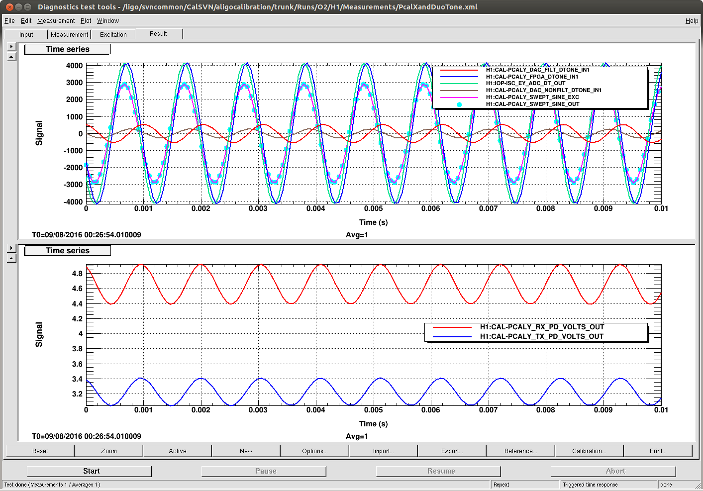
We injected a 960 Hz signal in H1:CAL-PCALY_SWEPT_SINE_EXC and recorded the following time series (see figure attached):
H1:CAL-PCALY_TX_PD_VOLTS_OUT
H1:CAL-PCALY_RX_PD_VOLTS_OUT  (measured to be equivalent to the TX_PD channel)
H1:IOP-ISC_EY_ADC_DT_OUT
H1:CAL-PCALY_FPGA_DTONE_IN1
H1:CAL-PCALY_DAC_NONFILT_DTONE_IN1
H1:CAL-PCALY_DAC_FILT_DTONE_IN1
H1:CAL-PCALY_SWEPT_SINE_EXC
The phase of the H1:IOP-ISC_EY_ADC_DT_OUT signal (measured at 65k) is determined from the amplitude of the signal at time T=0 with respect to the overall peak amplitude. We measured -2551 cts amplitude at T=0, where the sine wave has a peak amplitude of 4090 cts. The arcsine of the ratio gives the phase of -38.6 degrees in the range of -90 deg. to +90 deg. Since the true phase is outside of this range (more negative) we wrap instead to 180+38.6 = 218.6 degrees. This is the reference phase of the DuoTone signal.
We repeated the measurements to find the phases of all of the channels:
H1:IOP-ISC_EY_ADC_DT_OUT           = 218.6 deg <---- marked as time T=0
H1:CAL-PCALY_FPGA_DTONE_IN1        = 203.8 deg <---- also T=0 but filtered by the digital AA
H1:CAL-PCALY_SWEPT_SINE_EXC        = 219.4 deg
H1:CAL-PCALY_DAC_NONFILT_DTONE_IN1 = 182.7 deg
H1:CAL-PCALY_DAC_FILT_DTONE_IN1    = 100.2 deg
H1:CAL-PCALY_TX_PD_VOLTS_OUT       =  96.5 deg
H1:CAL-PCALY_RX_PD_VOLTS_OUT       =  96.4 deg
The difference in phase of H1:CAL-PCALY_SWEPT_SINE_EXC to H1:CAL-PCALY_TX_PD_VOLTS_OUT is 122.9 degrees at 960 Hz (= 355.6 usec)
So now there is a weird discrepancy in our measurements. The H1:CAL-PCALY_SWEPT_SINE_EXC to H1:CAL-PCALY_TX_PD_VOLTS measurement says 290 usec. The timing diagram predicts 285 usec. The phase of the waves measured in a time series is 355.6 usec. The difference is about 61 usec.
Still open questions:
- Why doesn't the transfer function agree with the phase counting? Phase counting appears to have an additional 16k clock cycle that the transfer function does not have.
- Why does the NOFILT_DUOTONE path not have 2 16k clock cycles delay?
- This still does not answer why the DARM open loop gain model is missing ~45 usec delay (15 usec in sensing chain and 30 usec in the actuation chain)
- And we still don't understand the timestamp of the ADC "averaging" delay when it comes to these kinds of transfer function measurements