REMOVE SEARCH FILTER
SEARCH AGAIN
Search criteria
Section: X1
Task: SUS
R. Crouch, J. Oberling, I. Abouelfettouh, O. Patane
As Ibrahim reported here, we have completed the first round of BBS position alignment (I say first round as we still have to do the pitch/yaw alignment, and that has the potential to change the position alignment so we may be doing this again). In the basis of our alignment equipment, which is set normal to the AR face of the BBS, the deviations from nominal are:
If we rotate these deviations to the XYZ axes using the BBS yaw we get deviations along those axes. I'm using the target BBS yaw for this (specifically, the AR surface yaw from the +X axis of 45.1056°), as we have yet to measure or align the actual BBS yaw, so this is more of an estimate at this point but will work for now (it takes a yaw change on the order of several degrees to change this calculation at the 0.1 mm level, so this is a pretty good estimate); this will be tightened up once we align the BBS pointing and revisit the positioning. The results (the tolerances rotate with the deviations, hence the change in X and Y):
The below table gives the target position of the center of the BBS's AR surface and the current position based on the above estimate of the XYZ deviations (all units are in mm):
| Axis | Target Position | Actual Position | Deviation | Tolerance |
| X | -160.4 | -160.5 | -0.1 | +/- 1.4 |
| Y | -226.3 | -225.8 | +0.5 | +/- 1.4 |
| Z | -83.1 | -83.2 | -0.1 | +/- 1.0 |
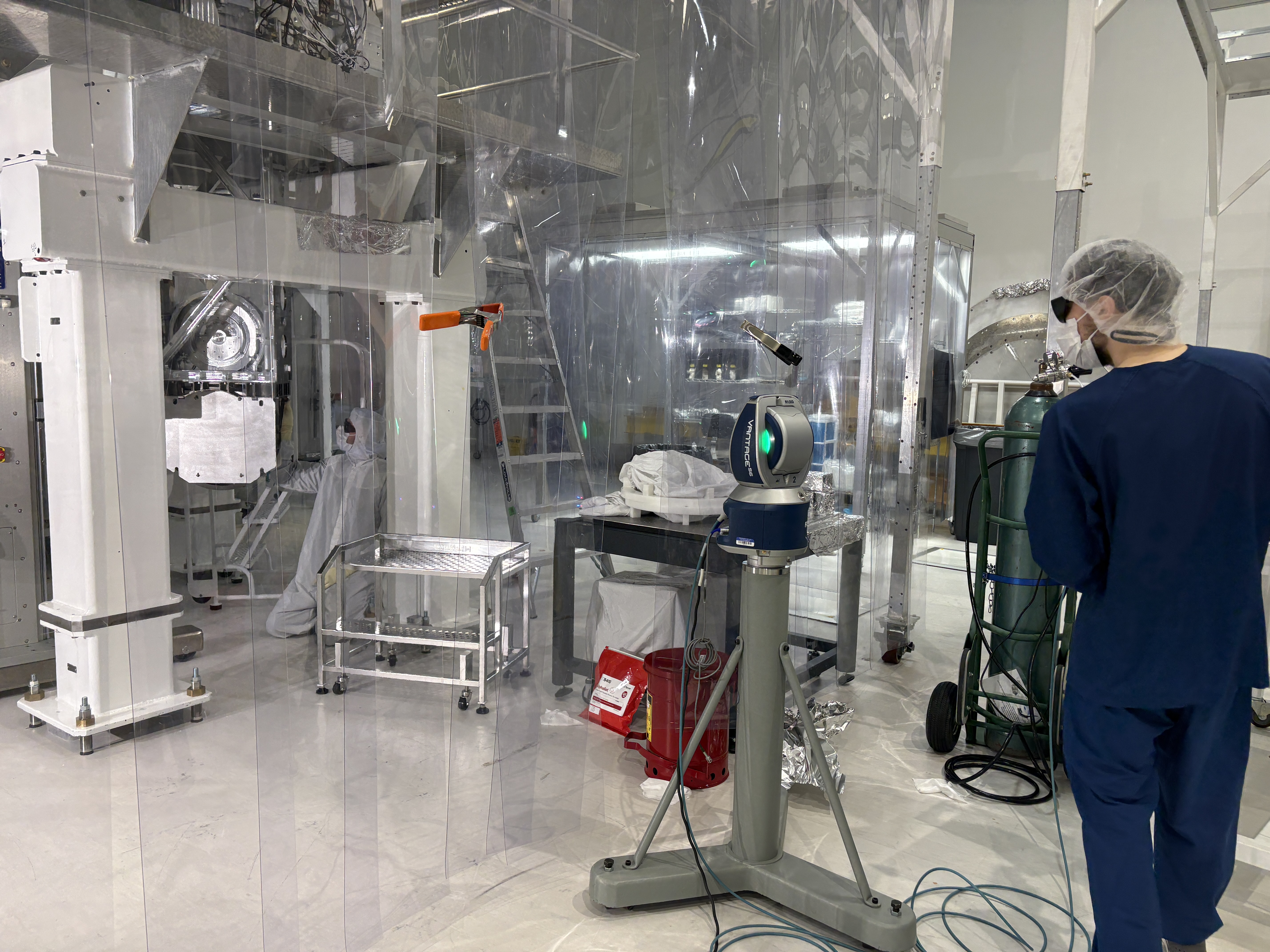
The next step in the alignment is to use the FARO to set up a total station/laser autocollimator combo looking along the target surface normal of the HR surface of the BBS. This will be used to align the BBS pitch and yaw. Once that is done we'll have to re-check the BBS position alignment (again, using the AR surface of the BBS) to ensure the pointing alignment did not change the optic's position (which may happen in this case as the BBS is currently, as Ibrahim reports, "quite yawed").
Ibrahim, Oli, Jason, Ryan C
Work done today:
Specifics of Optic XYZ Alignment
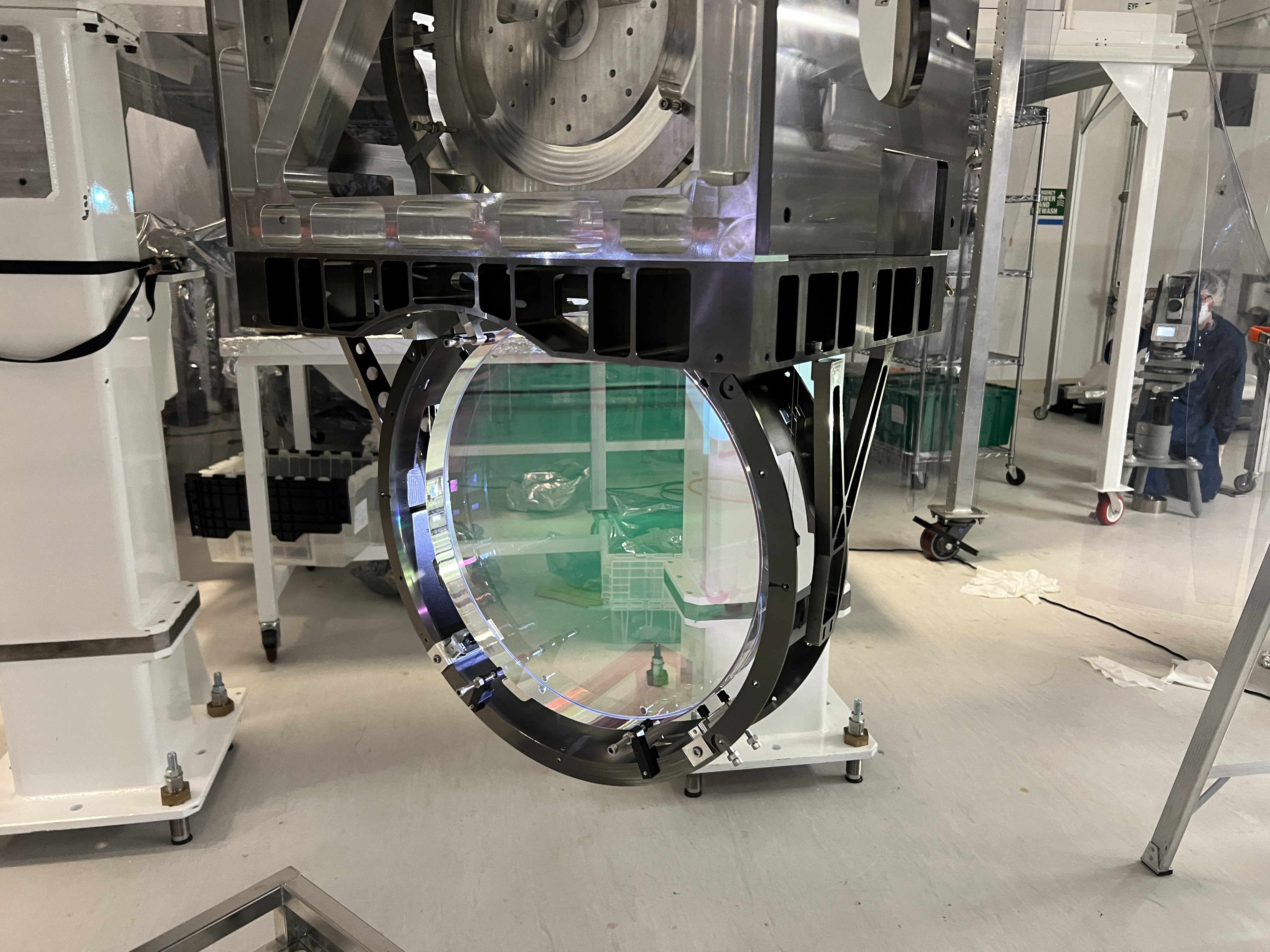
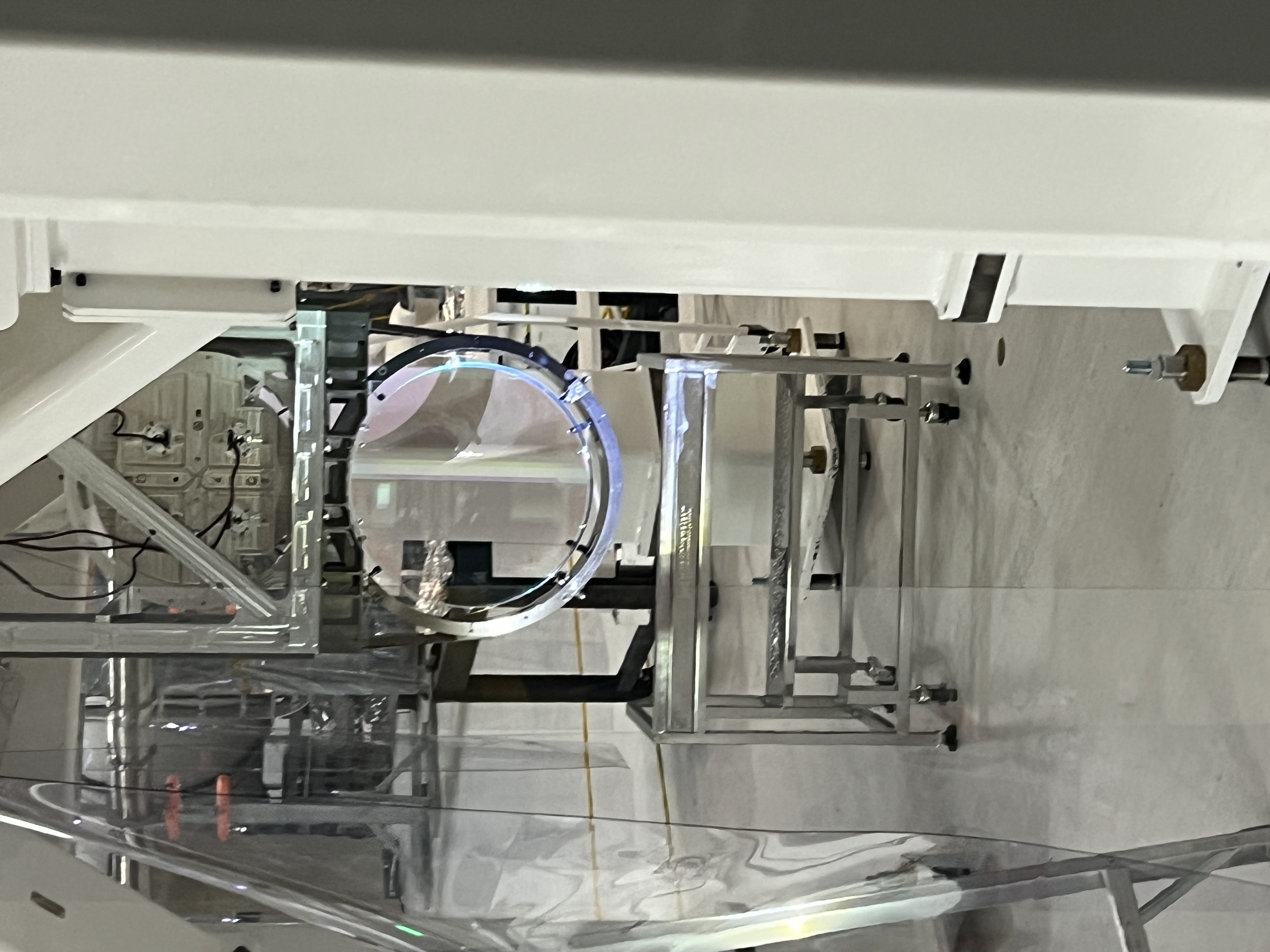
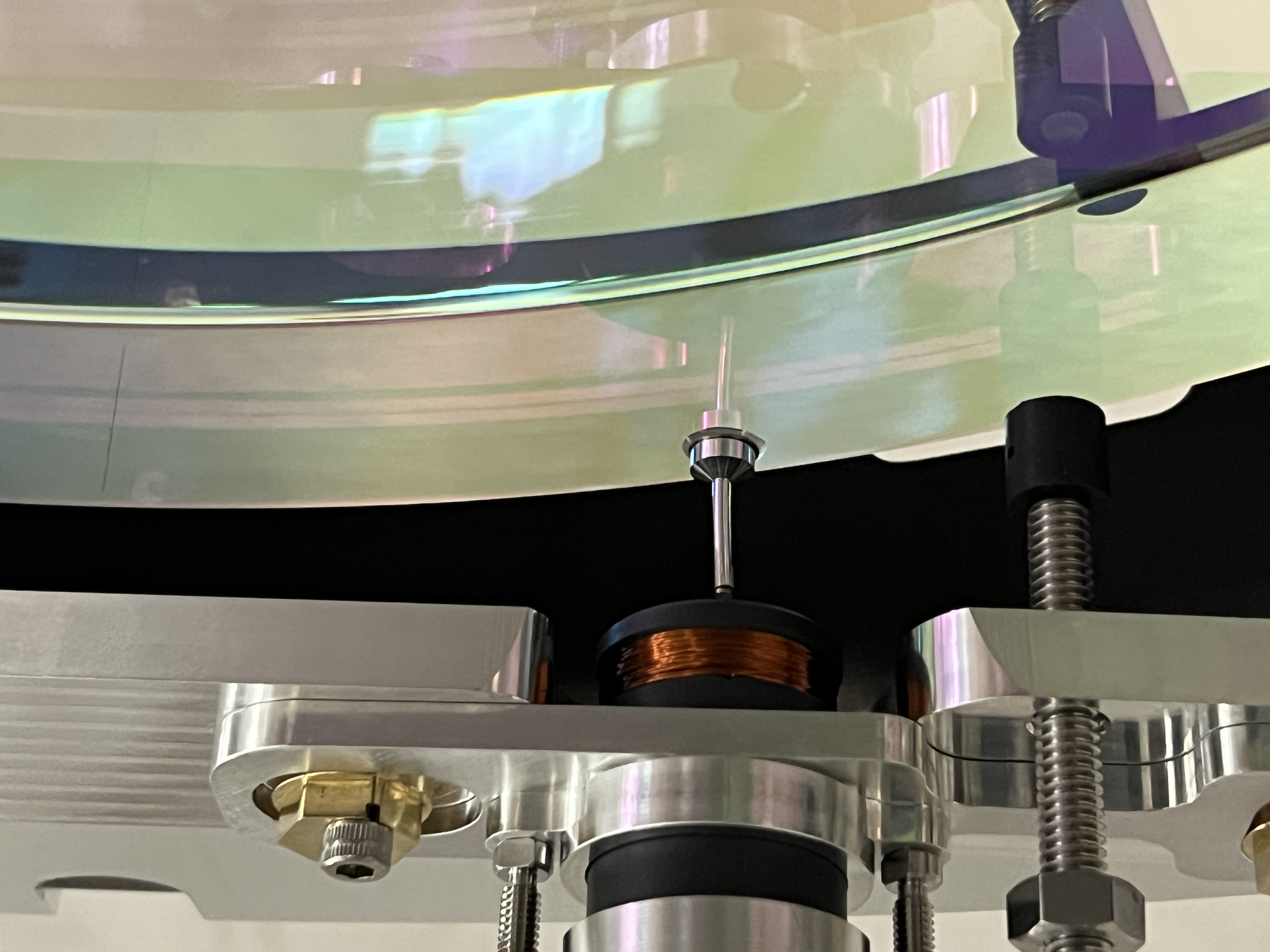
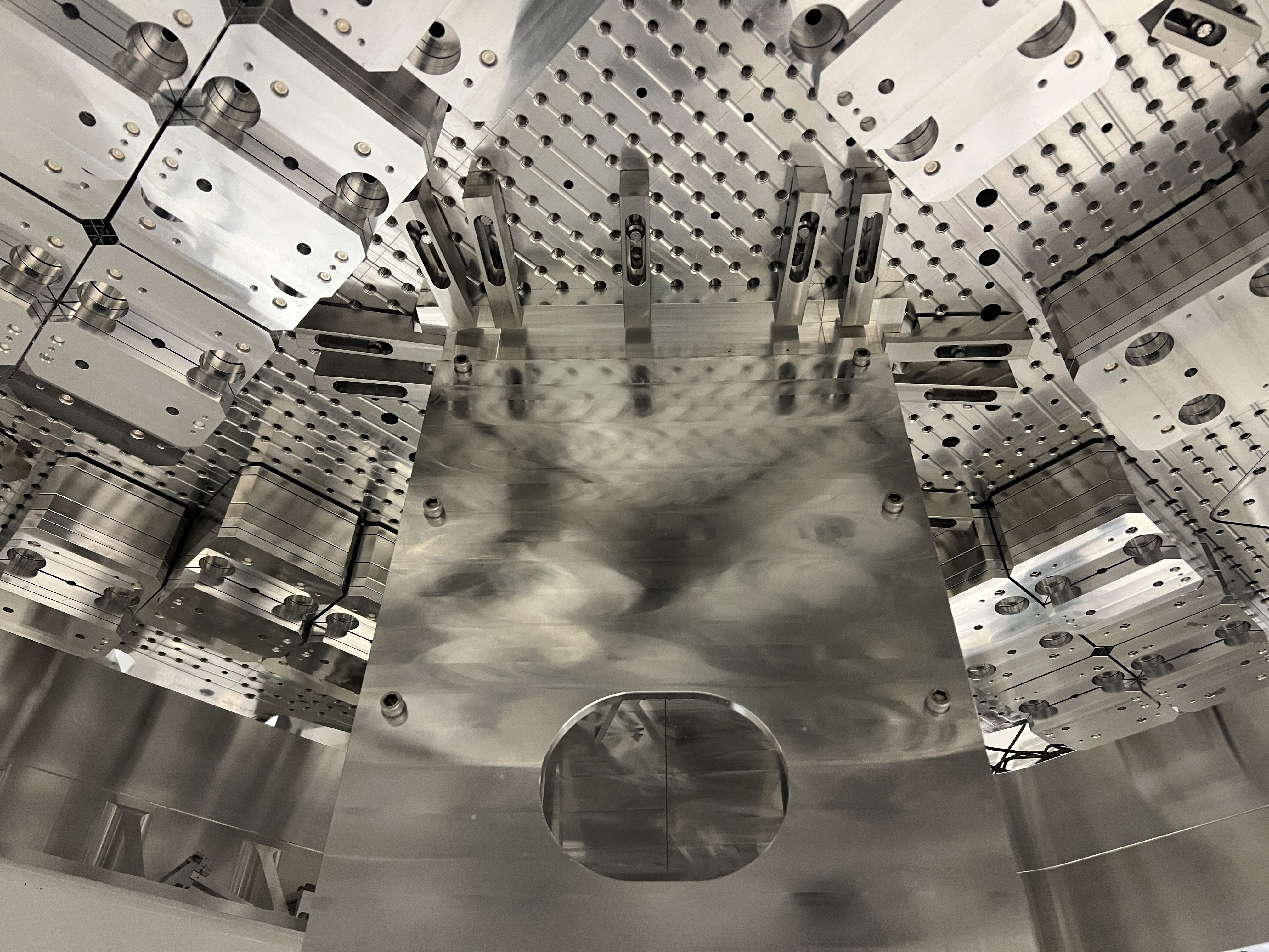
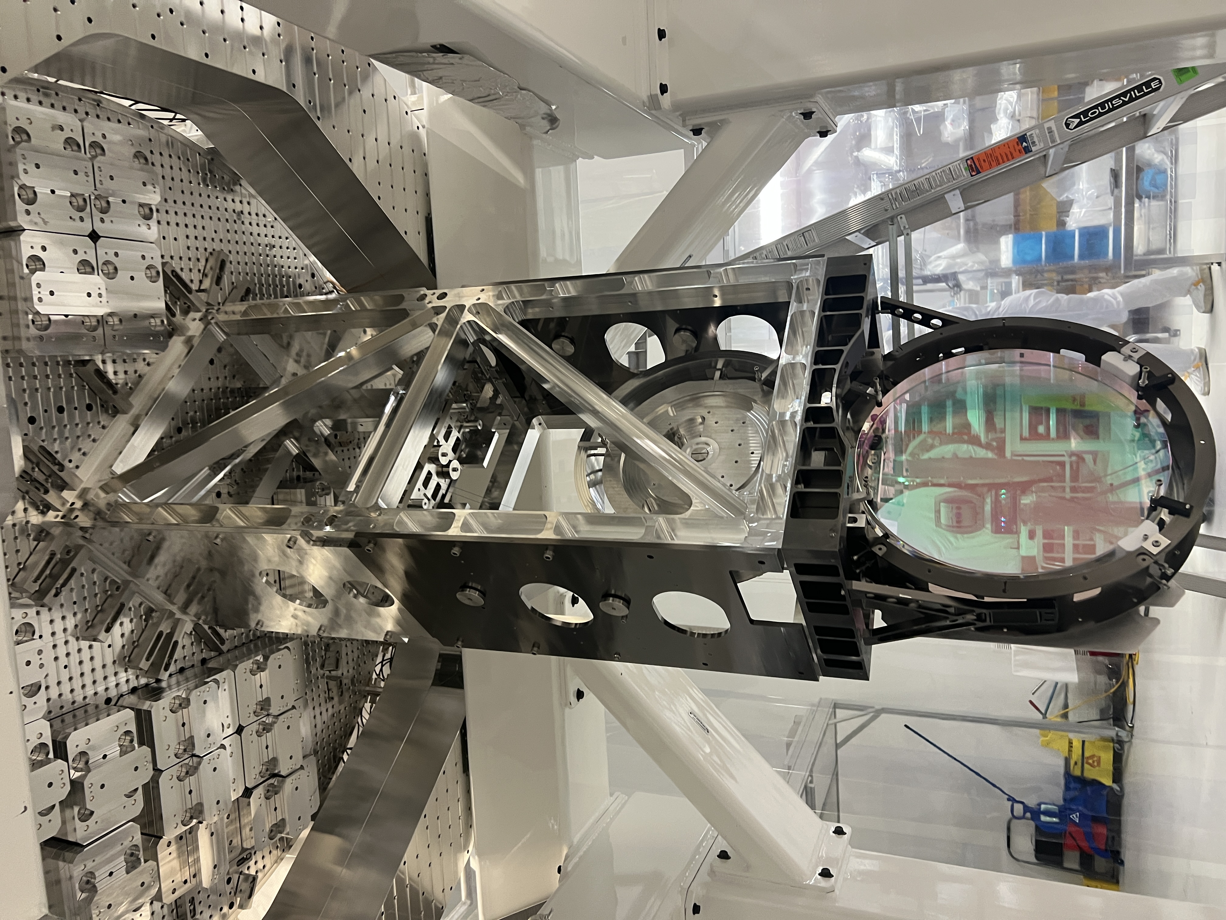
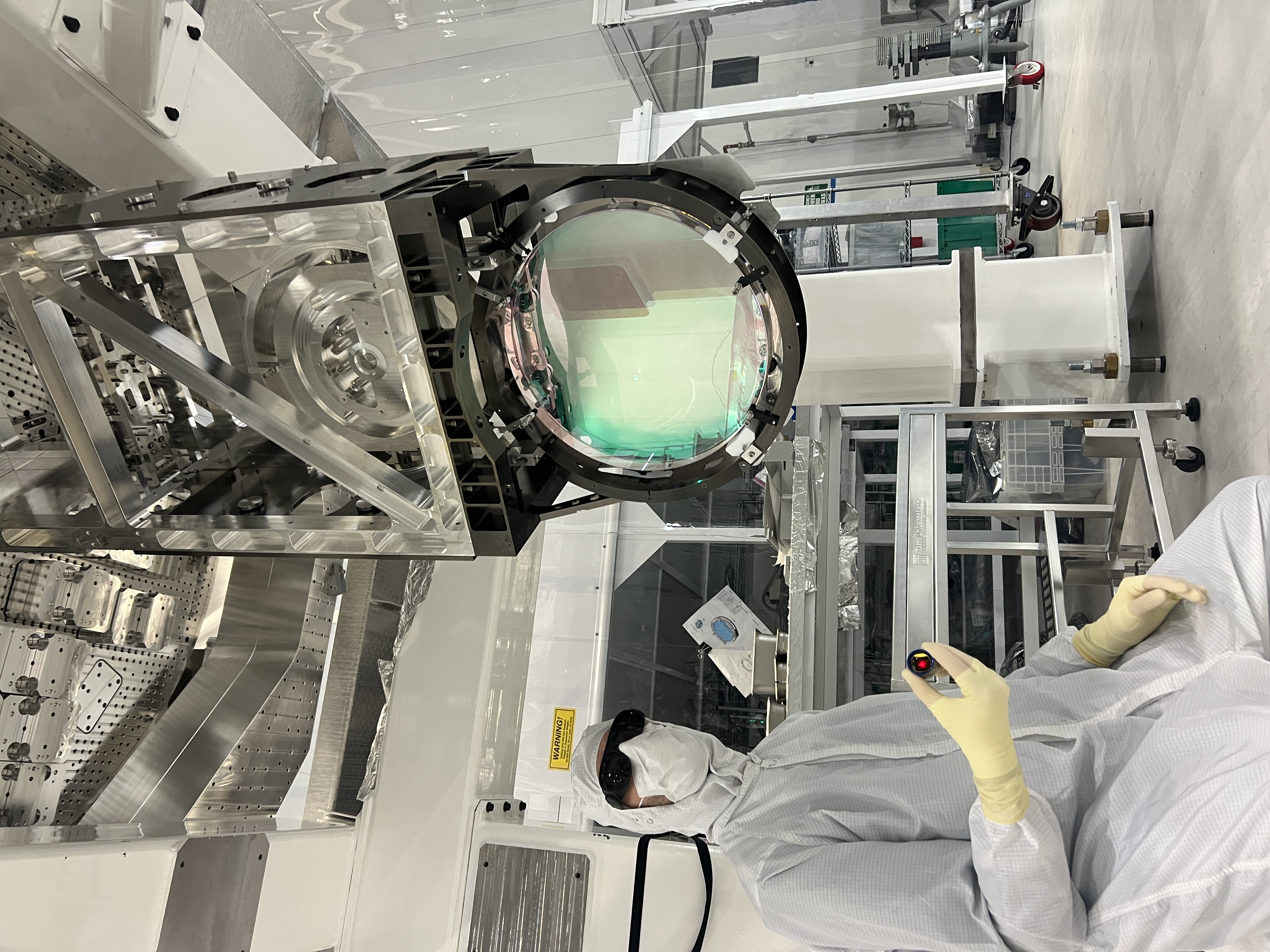
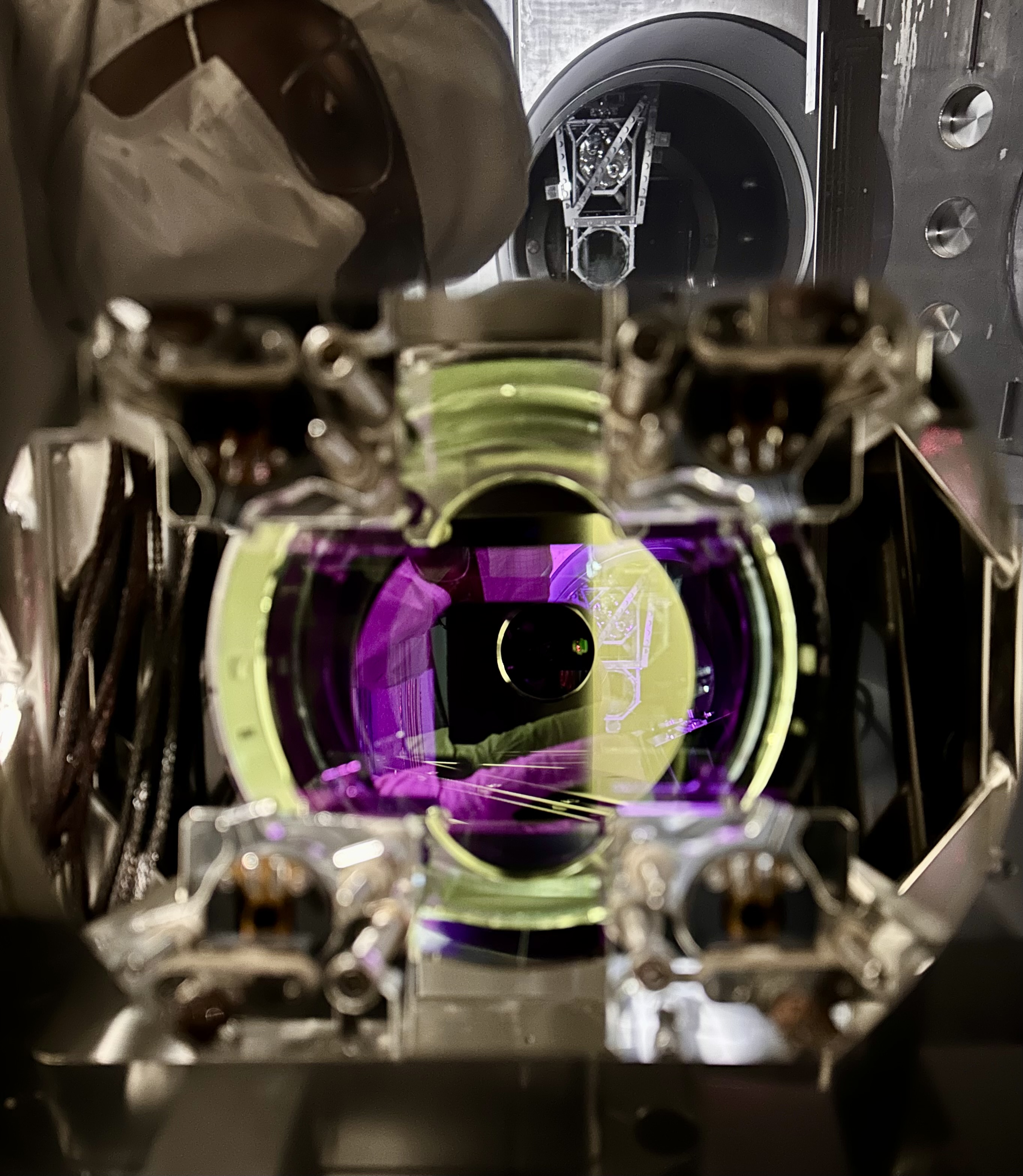
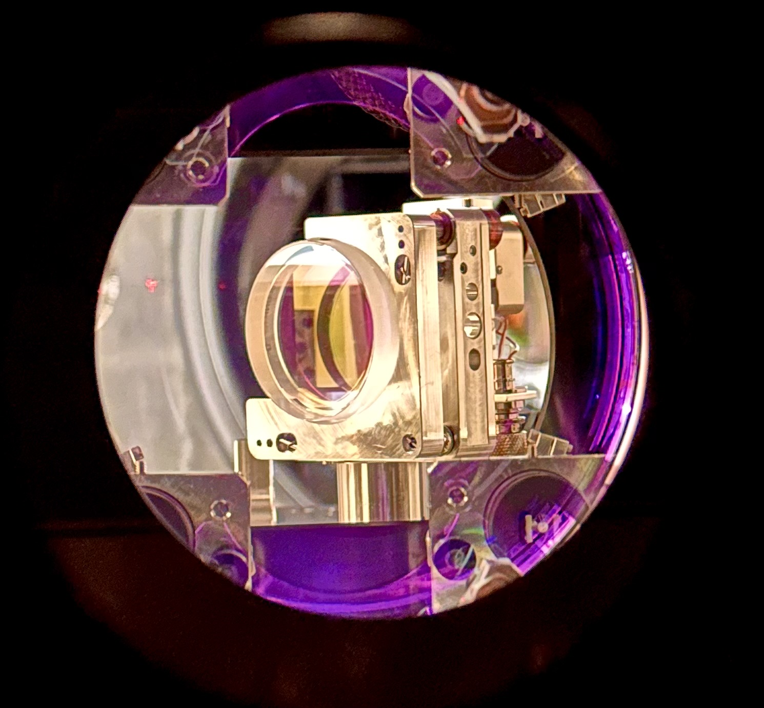
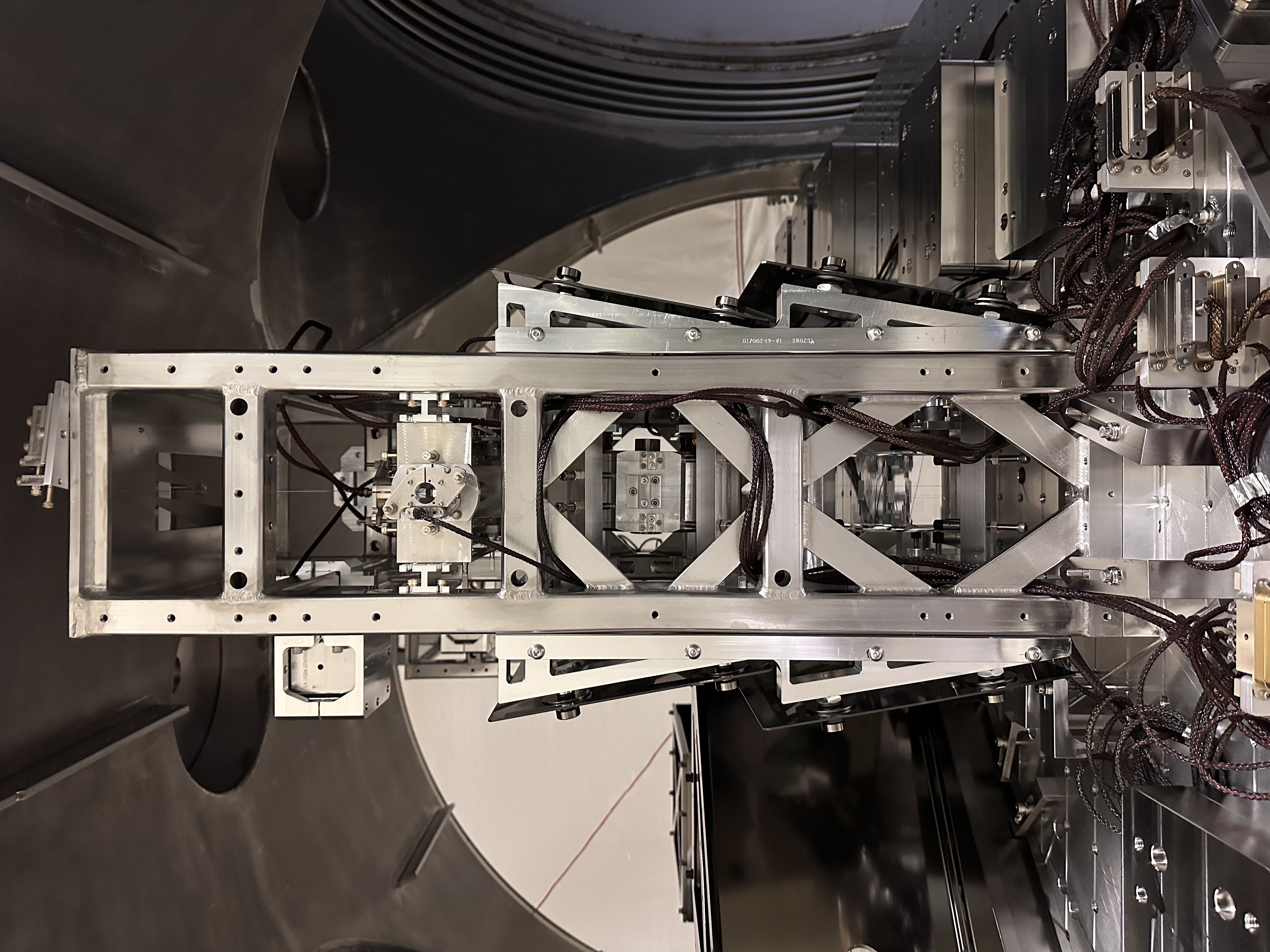
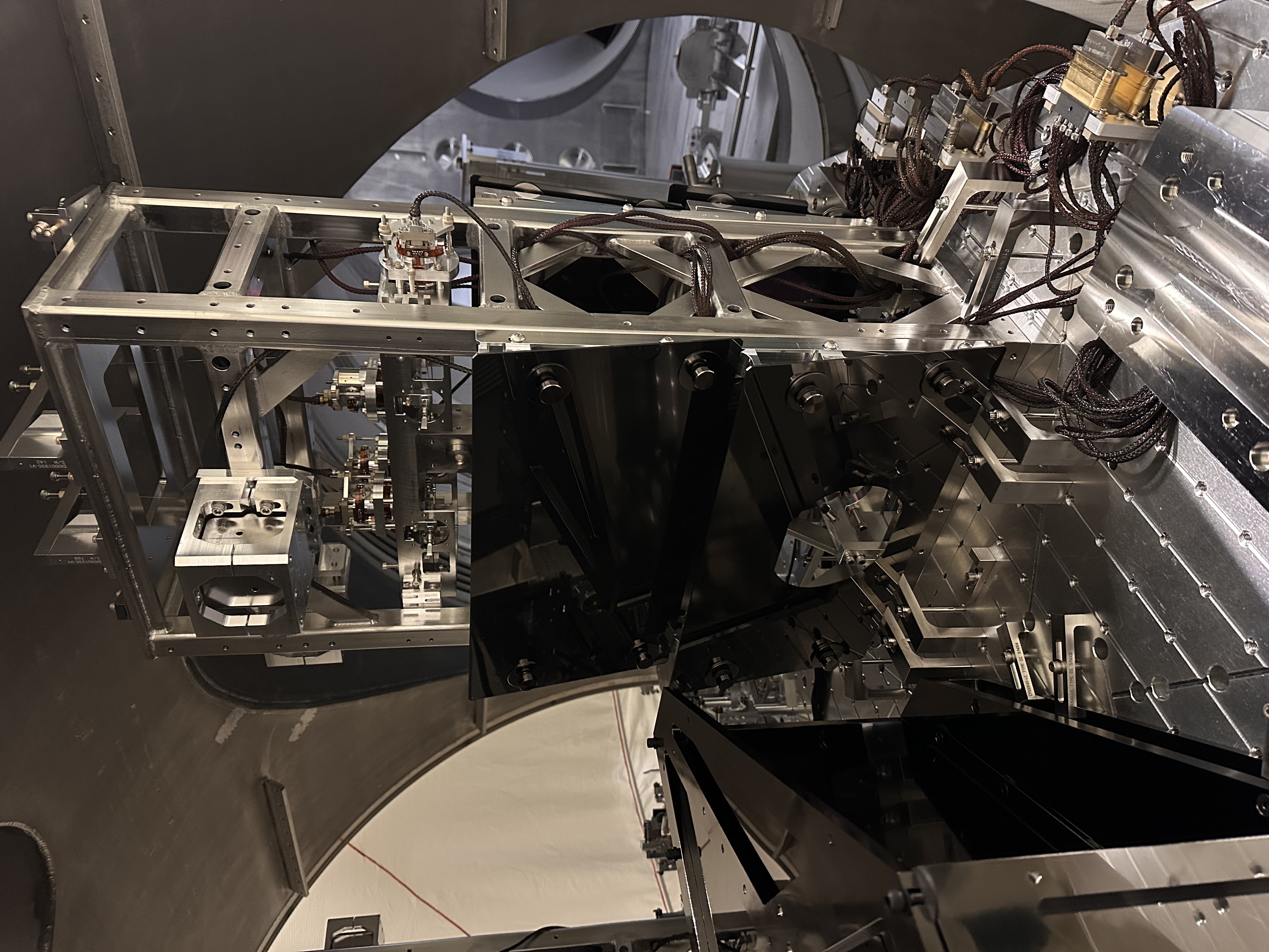
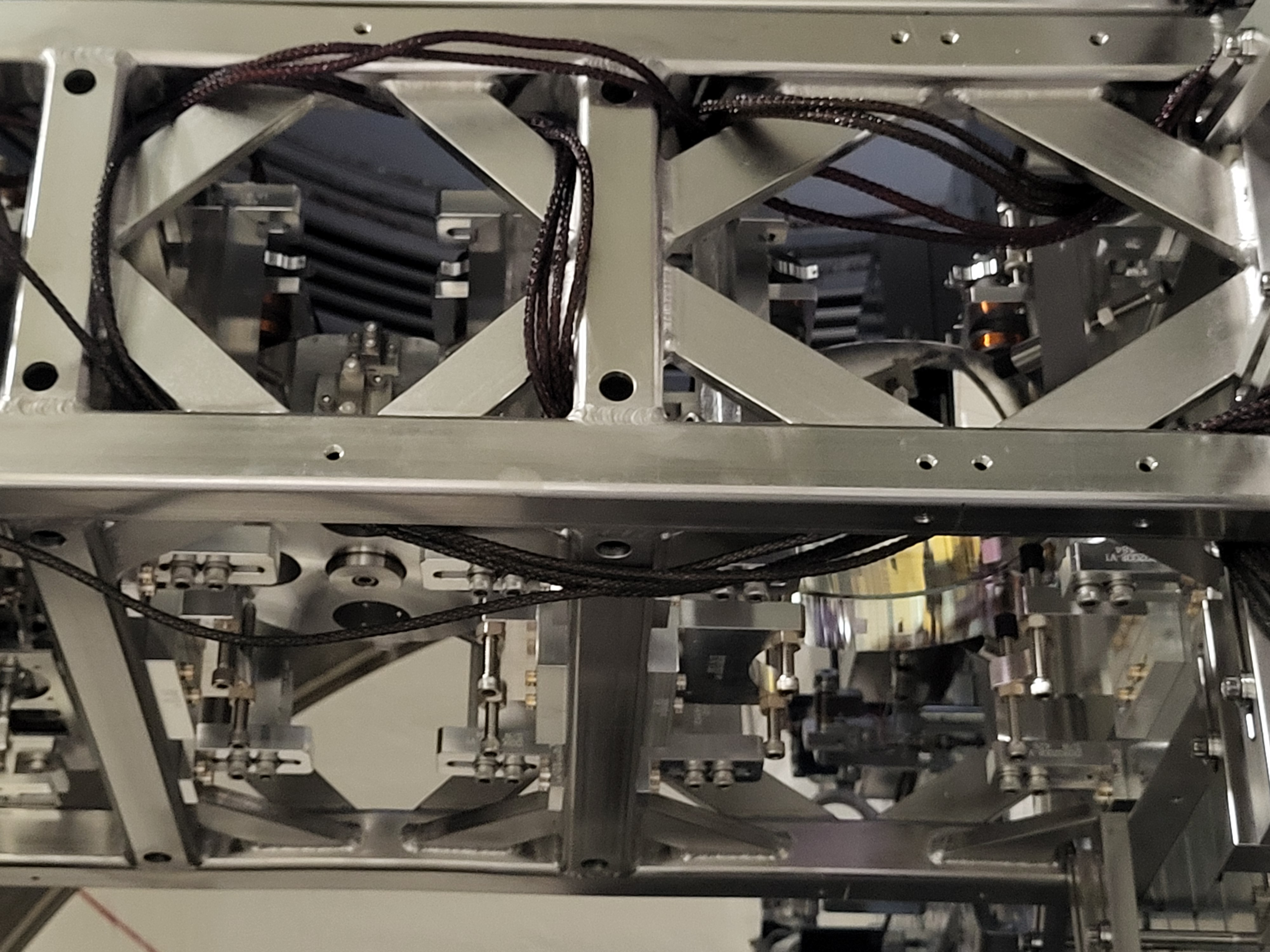
See pictures below.


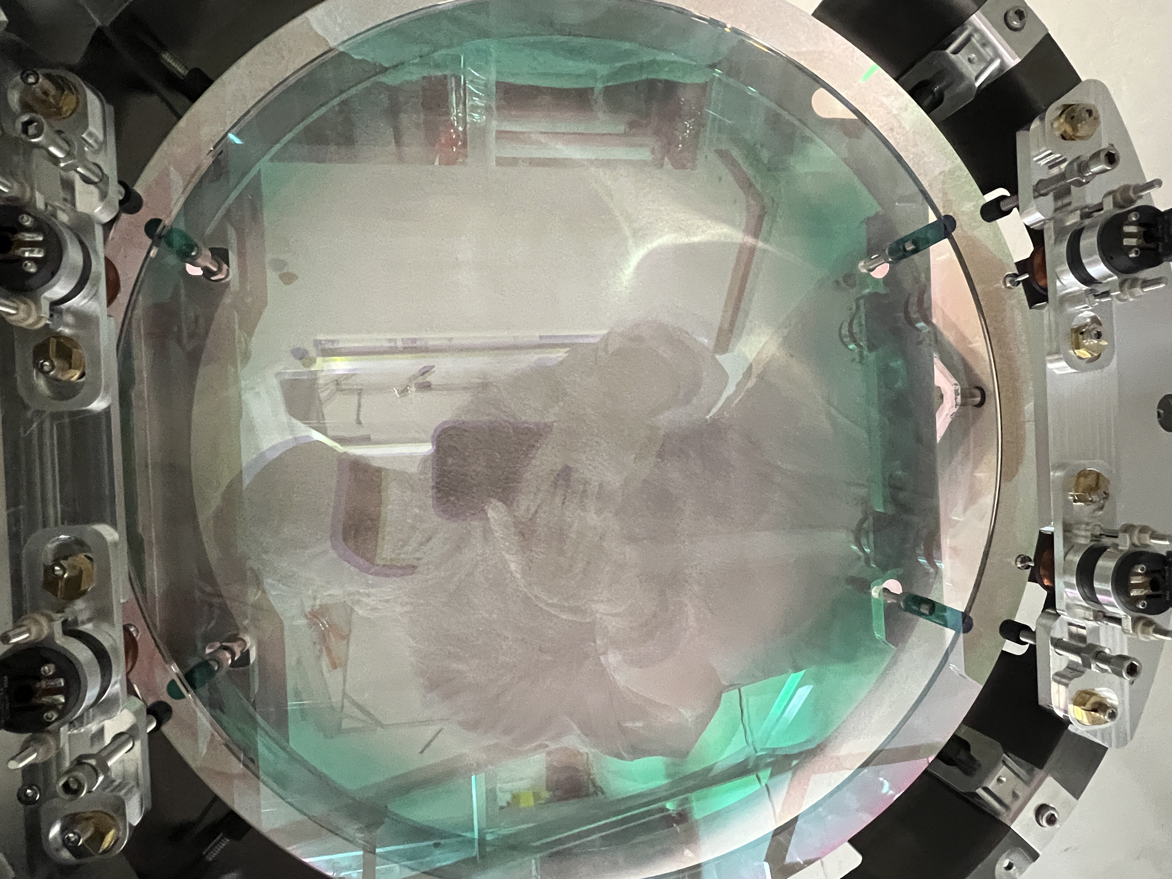
R. Crouch, B. Weaver, I. Abouelfettouh, J. Oberling, R. Thompson
Today we placed and aligned the BBS SUS cage on the WBSC2 ISI. In the morning we rough placed the SUS, and thought we had done a really good job on the first attempt. However, that was fed by a misread of how the Build/Inspect function in PolyWorks, well, works, and upon doing a more thorough measurement (directly measuring a constraining plane to inform SMR radius compensation instead of letting PolyWorks handle it automatically) we found there was a position and rotation error to the cage.
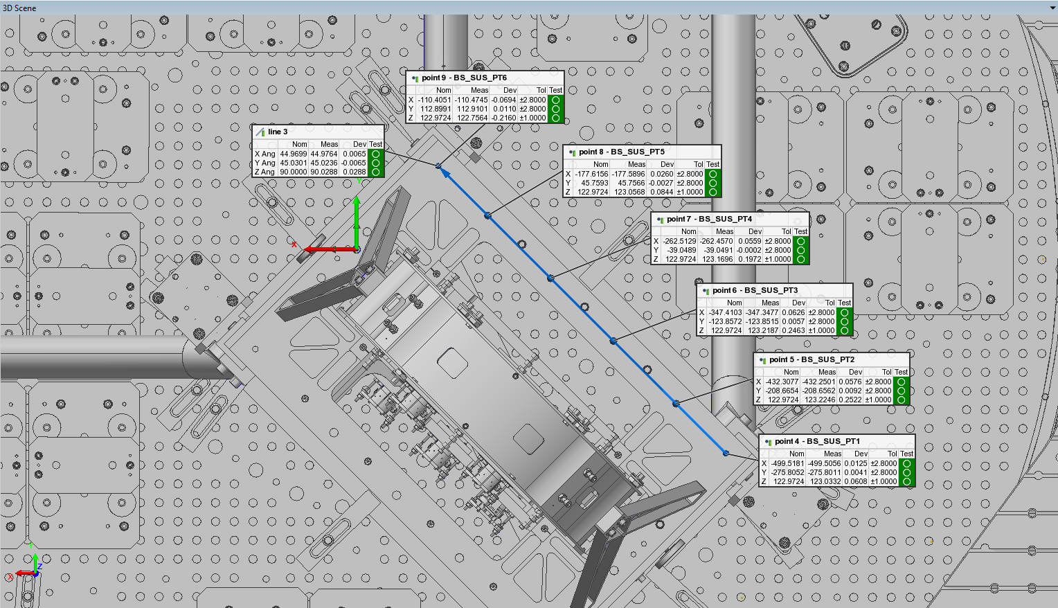
In the afternoon we moved the SUS cage around until things looked really good. We were well within our +/-1.0 mm XYZ tolerance, but once the SUS had been fully dog clamped to the ISI things shifted (as they do). In this case, it was roughly 0.5 mm in the +Y direction. All of our measurement points except one are within tolerance, so we called this good enough for SUS cage placement. To end, Ryan and I measured the circle that's defined by the lower section of the Figure 8 (the round section of the SUS cage that surrounds the BBS) on both the HR and AR sides of the cage. The first attachement shows the position deviations of the 4 points we used for cage placement/alignment and the current position of the HR and AR Figure 8; all except the Y axis position of 1 point are within our tolerance. The second attachment shows the rotation of the SUS cage w.r.t. the ISI; the angles listed are in degrees and are measured from the positive axes they are associated with (so X Ang is measured from the +X axis). These 2 lines show that the SUS cage is rotated roughly 400 - 500 µrad CCW (top-down view) from nominal.
Next up is to set up a total station looking at the AR face of the BBS to precisely align the optic to the ISI.

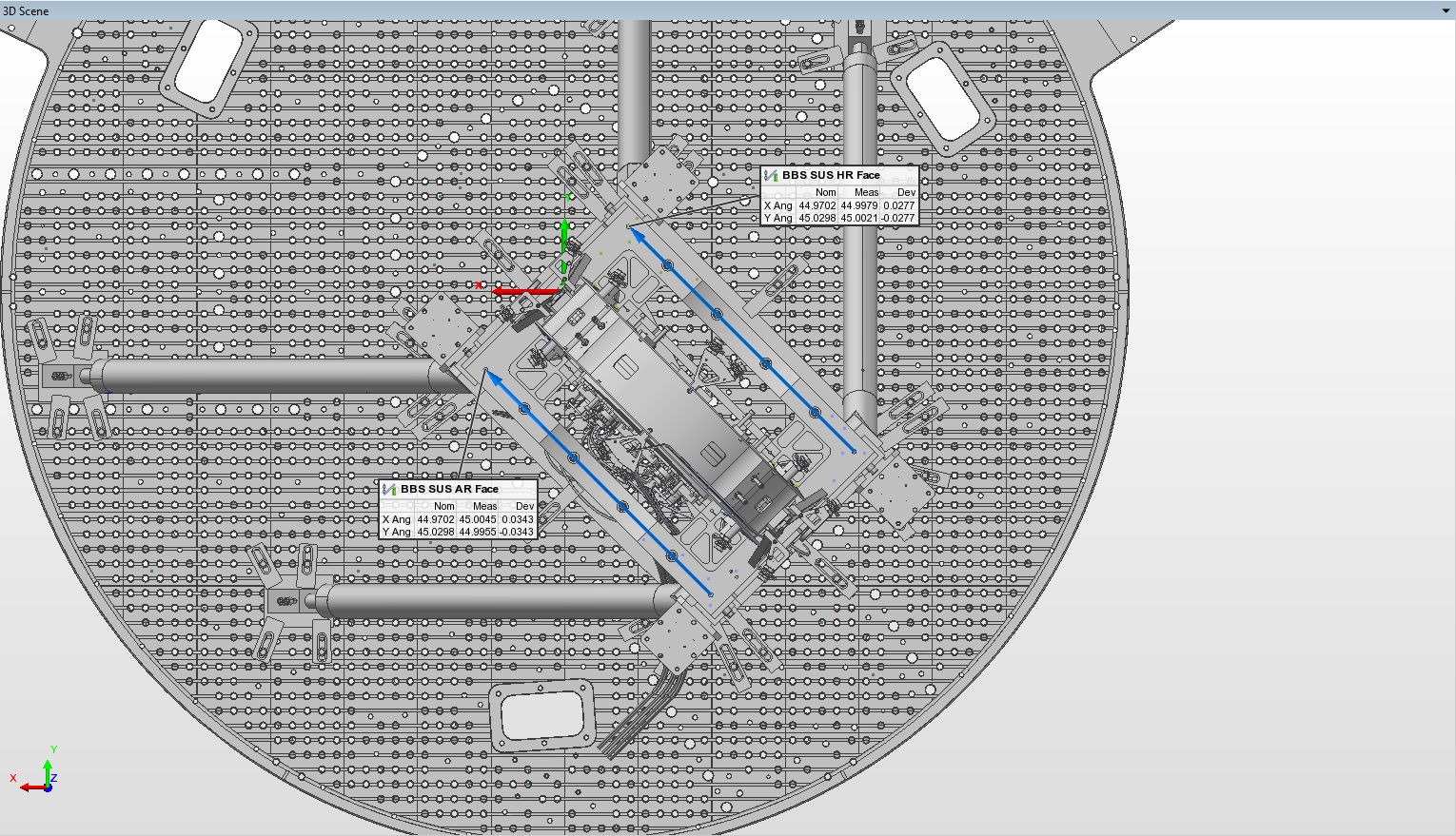
Ibrahim, Betsy, Randy, Jason, Ryan C
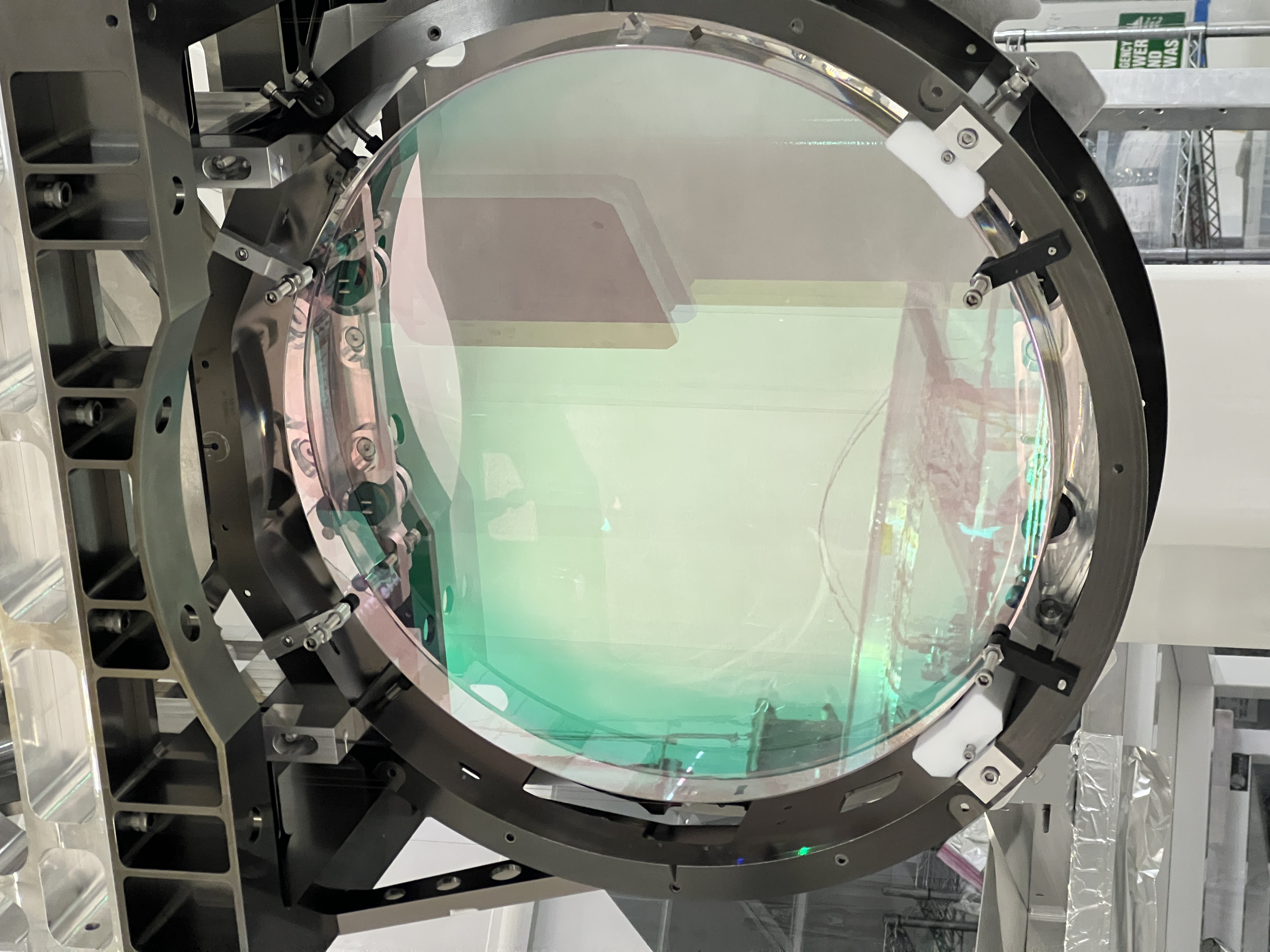
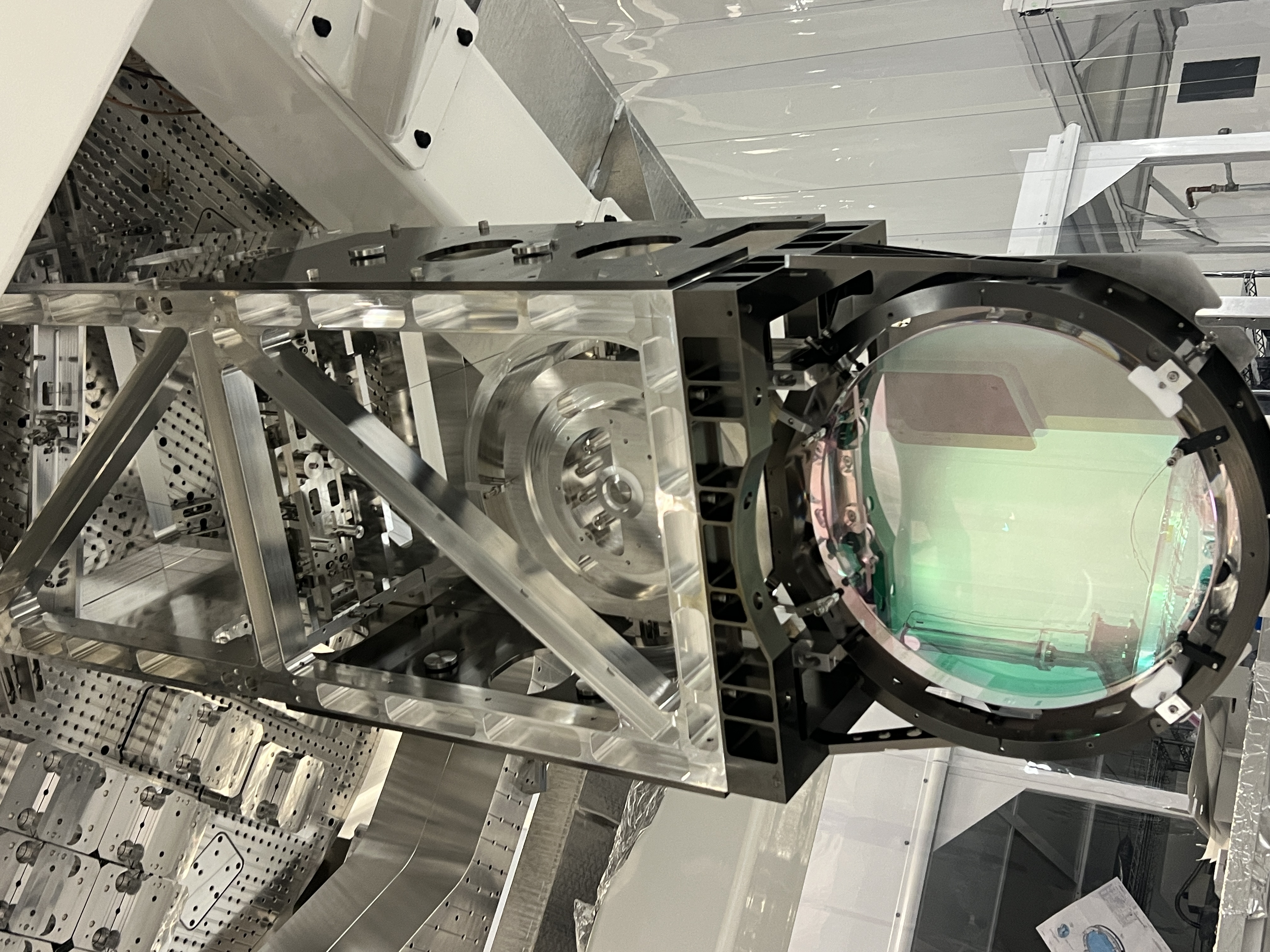
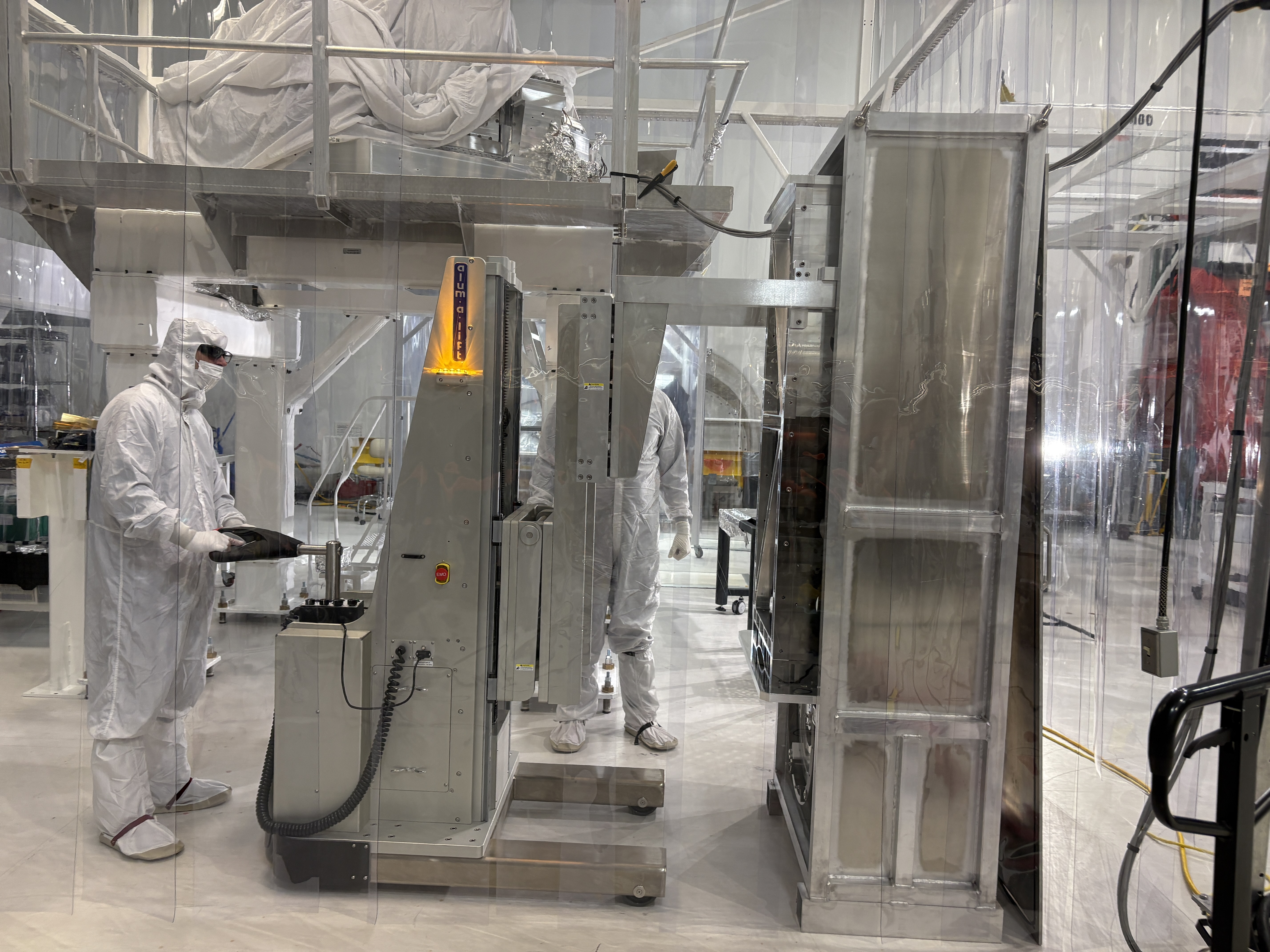
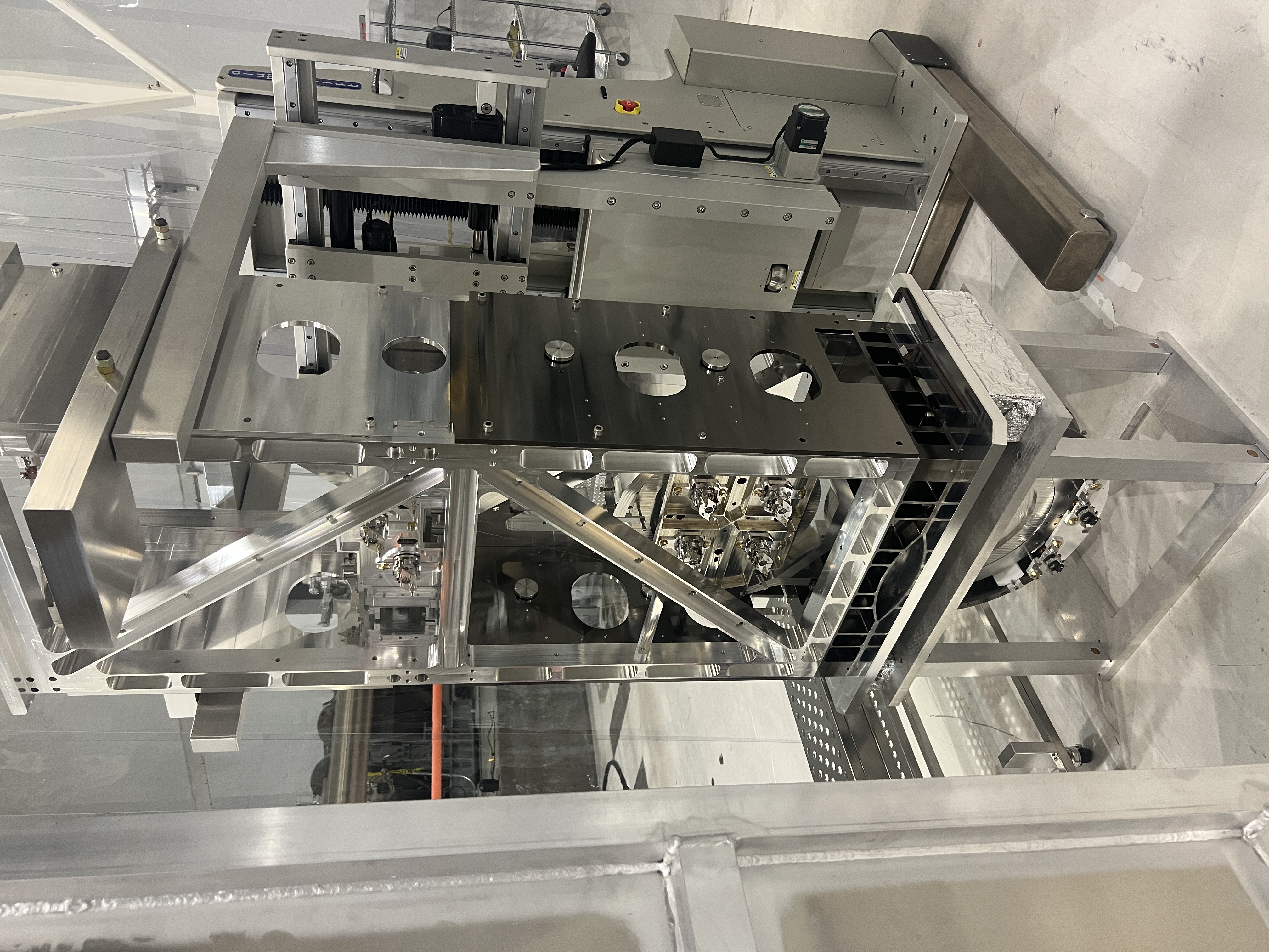
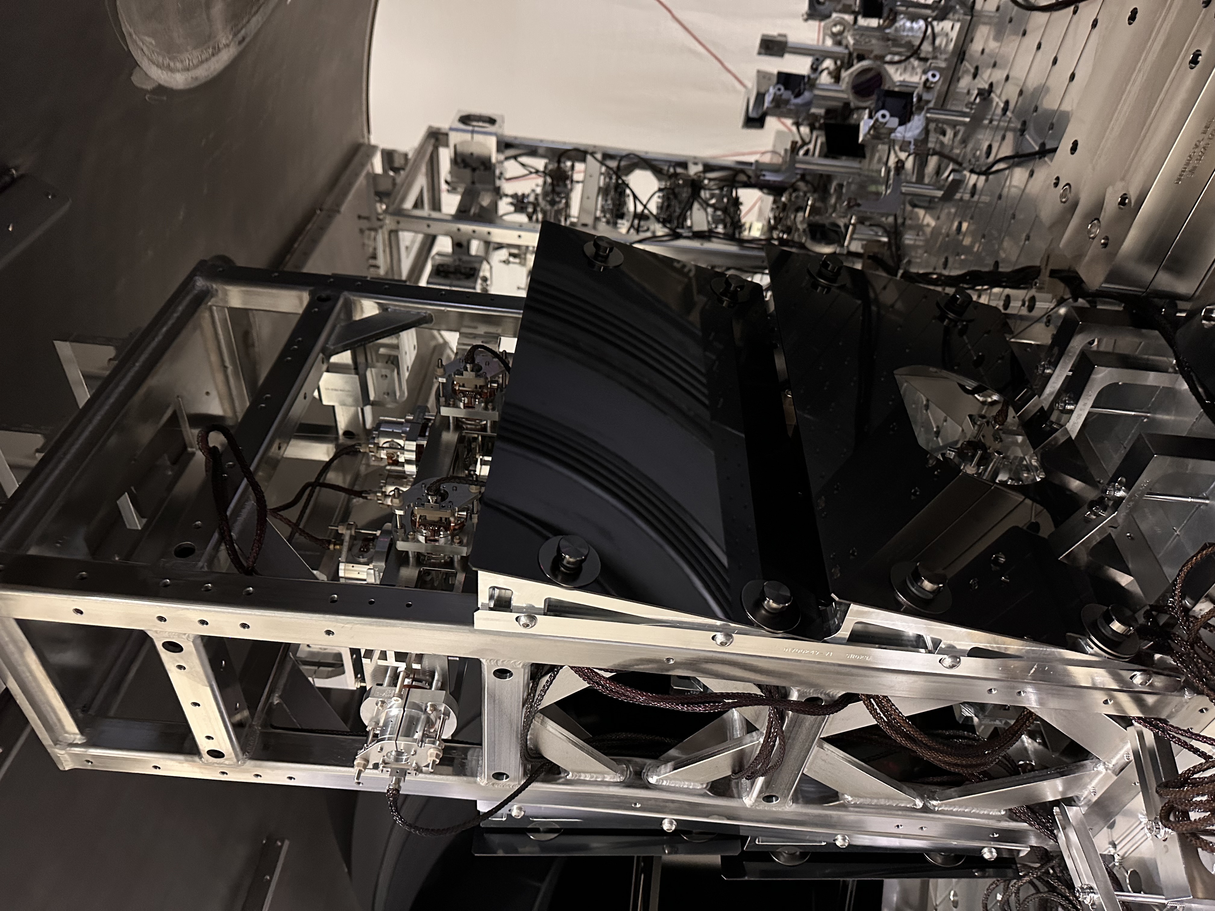
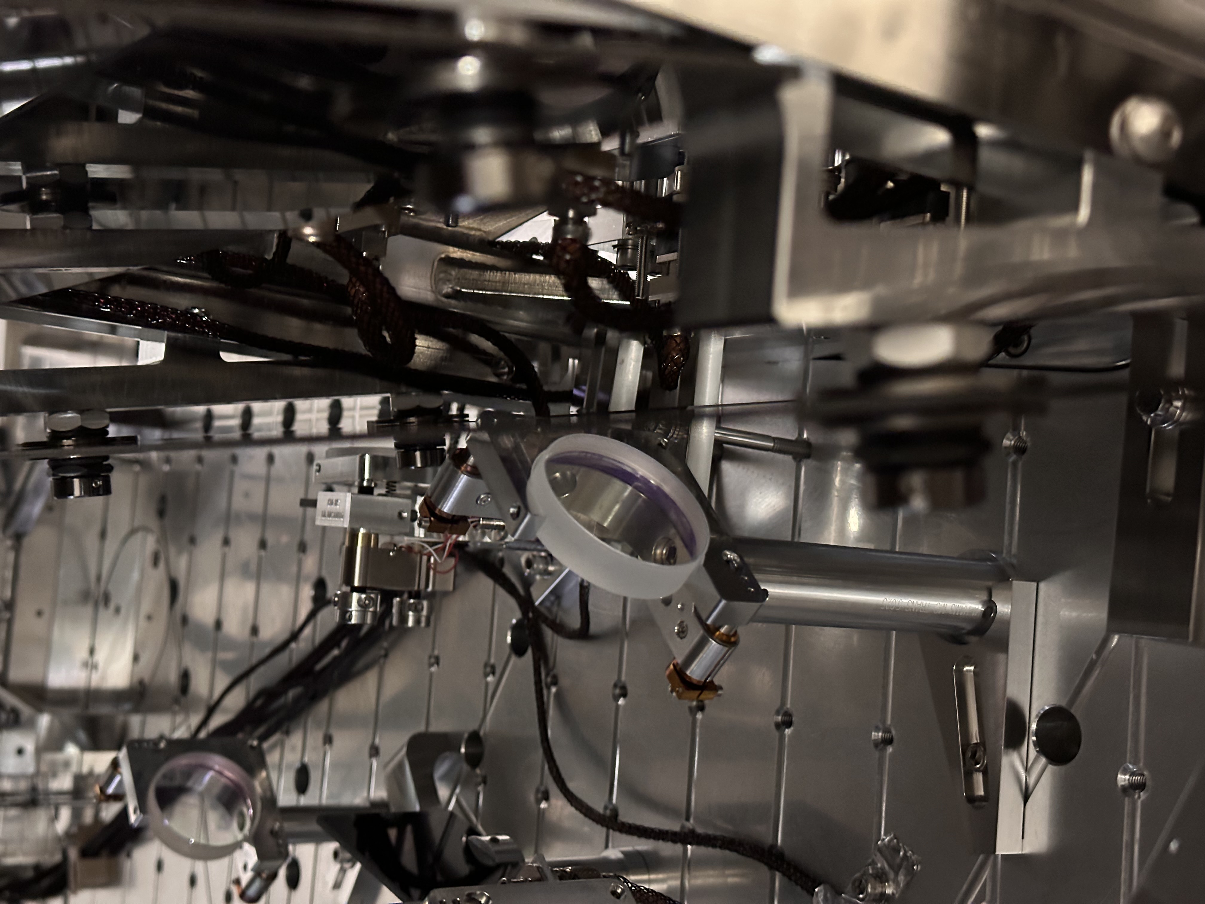
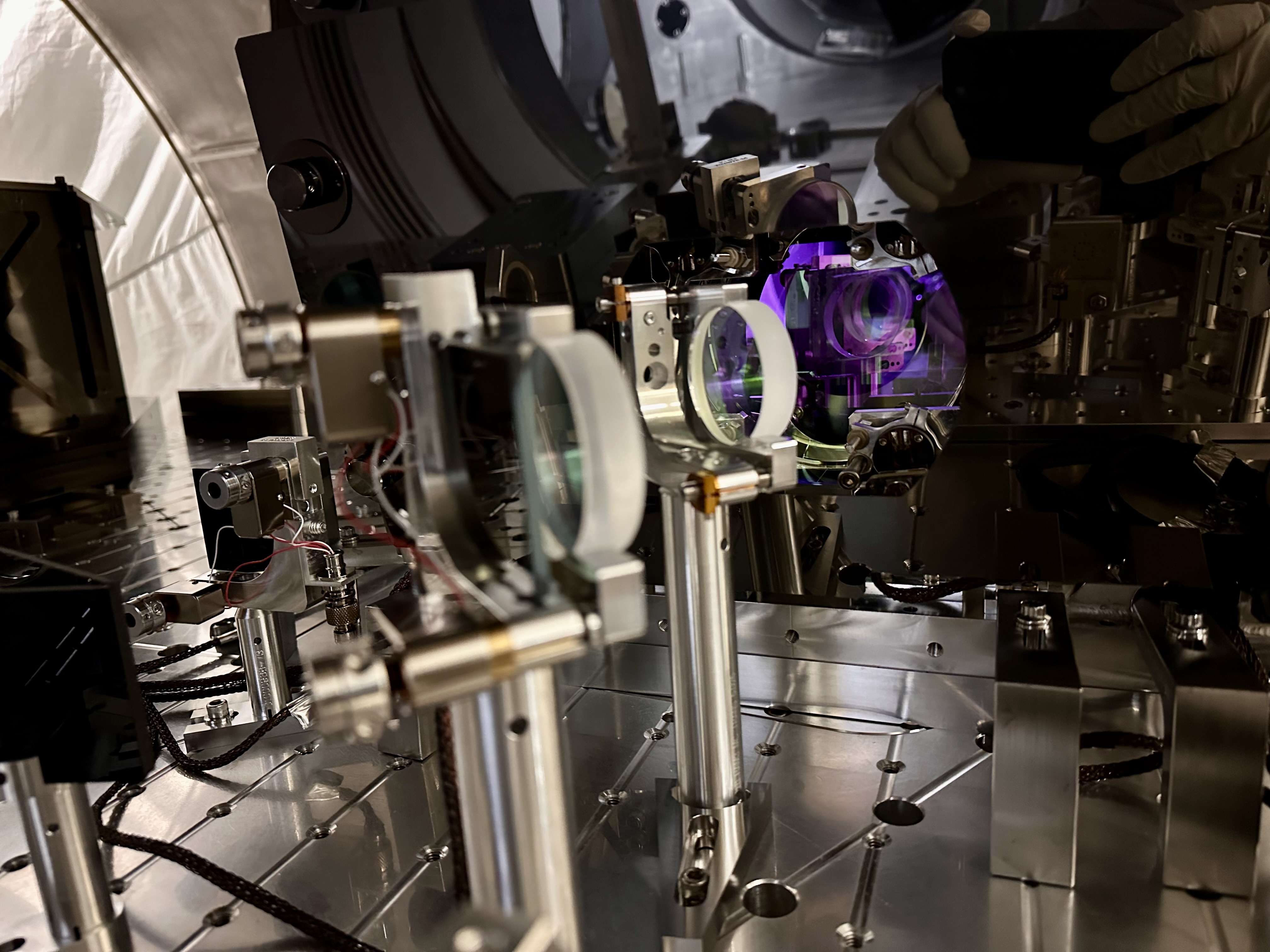
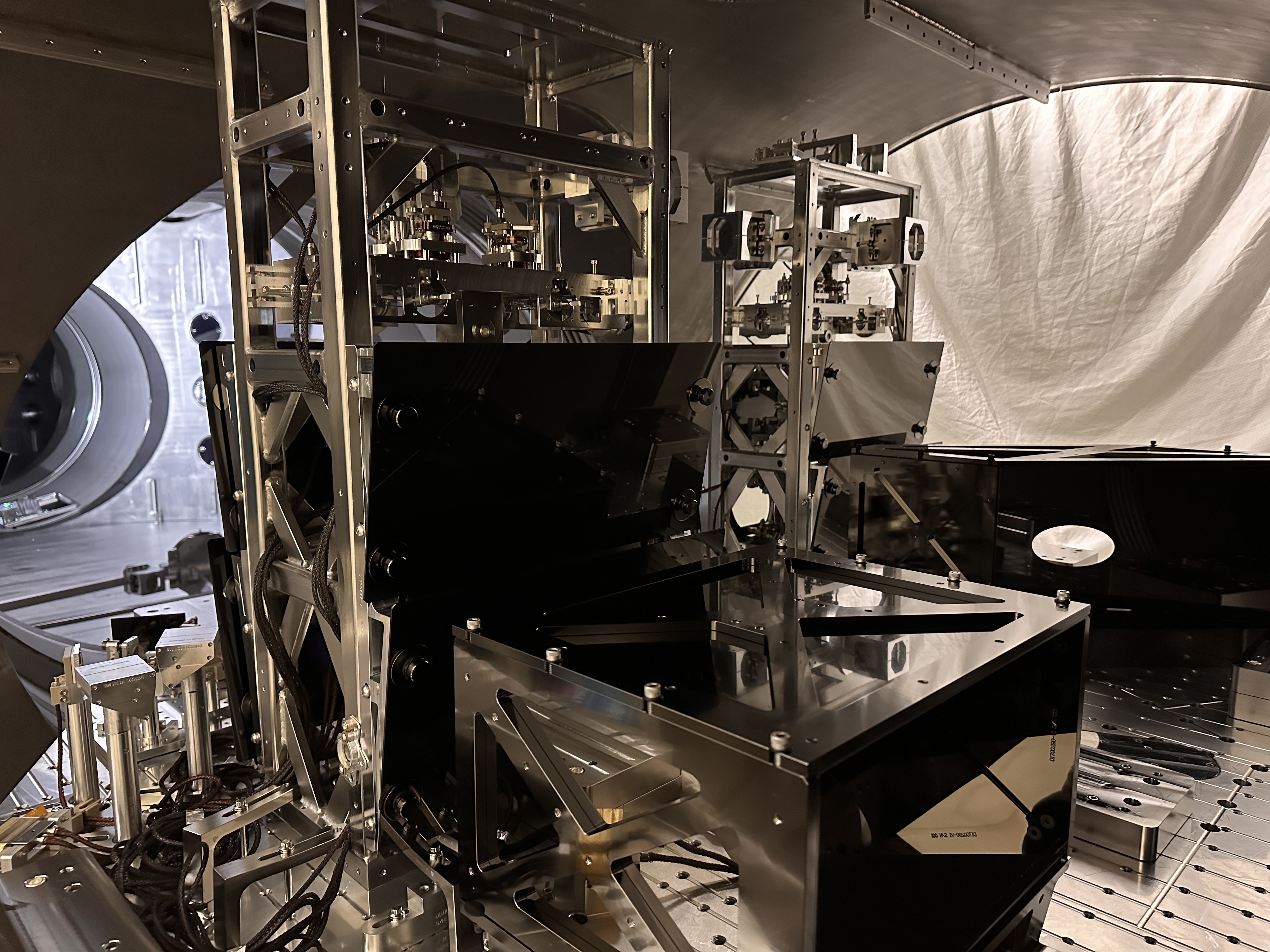
Today, we lifted the BBSS into the ISI. We then secured and aligned it with the help of IAS (Ryan C and Jason - seperate alog which will be linked later).
We used the aluma lift and dog clamps with the help of teflon pads to move the strucutre about the lift within dog clamp boundaries to align it to the ceiling to the model.
The alignment was done by touching the FARO SMR to the corners of the top of the lower structure to determine if translation or rotations were needed on the structure.
We also inspected BBS01 and found some particulate on the center of S1. Thankfully, it blew off using the N2 Top Gun.
Particle counts were checked in cleanroom periodically and were below 50 consistently.
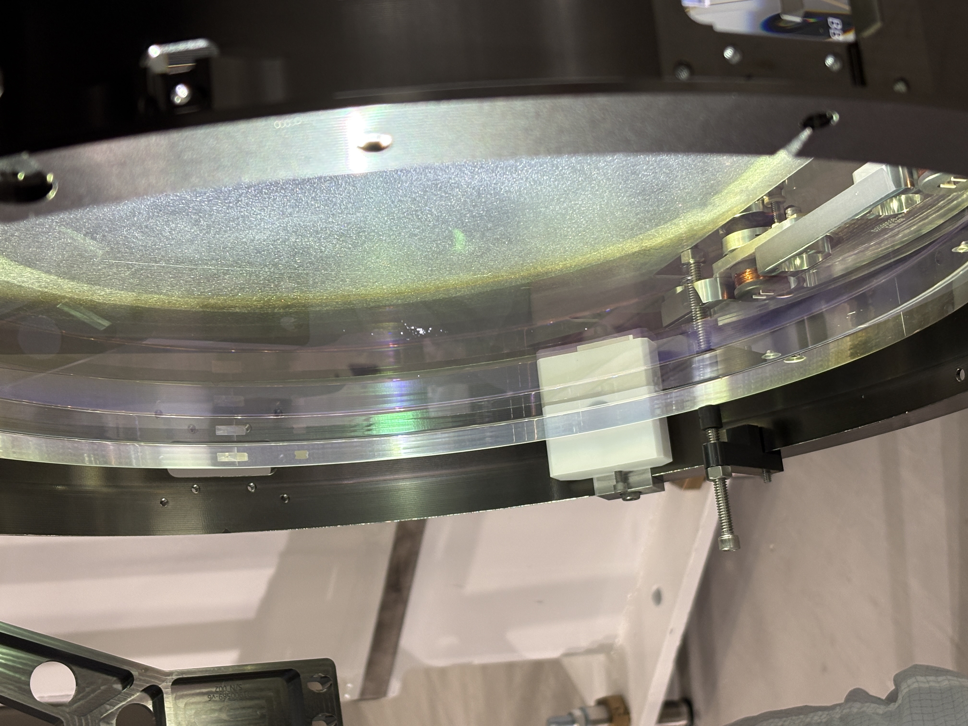
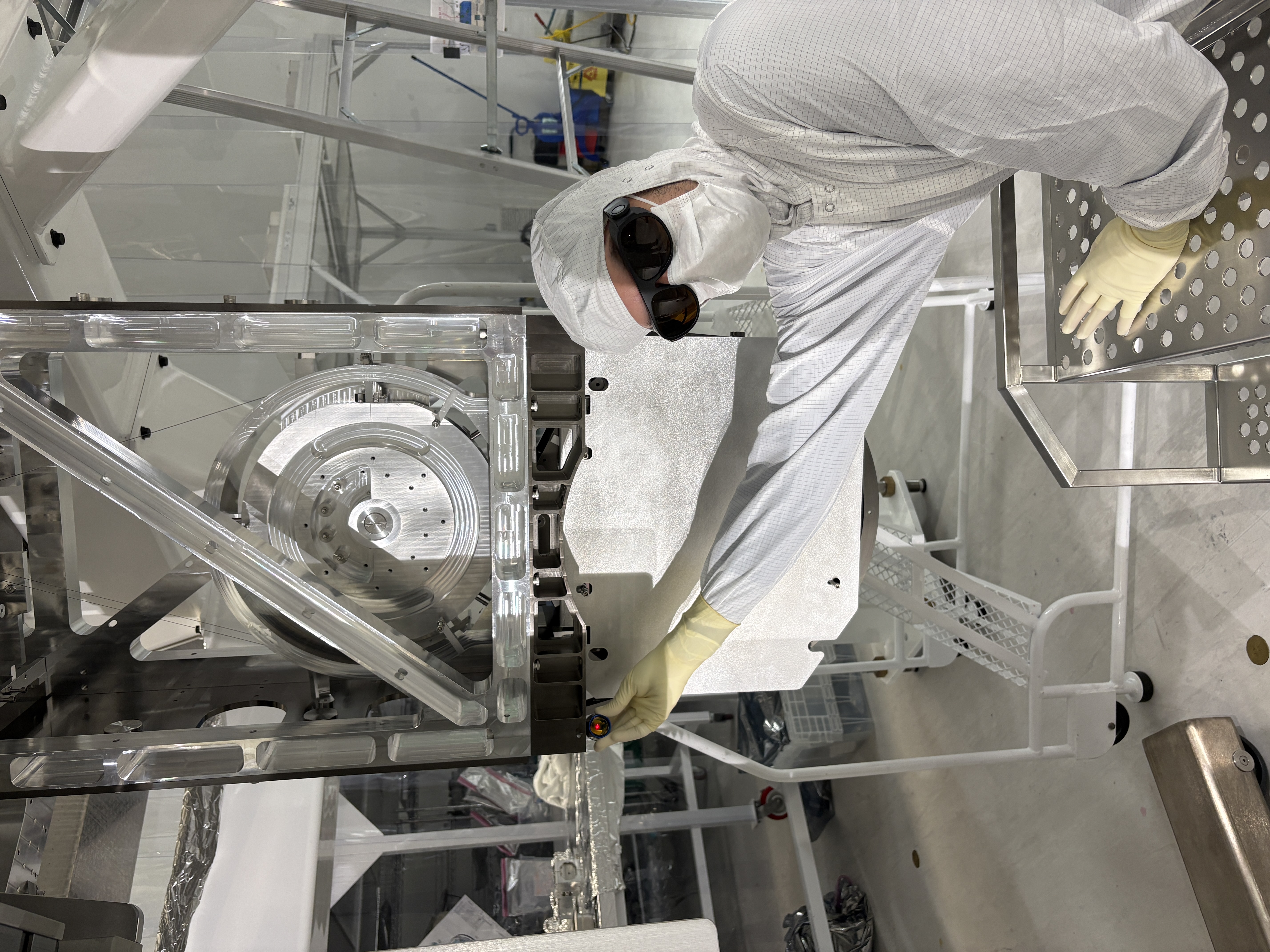
See pictures.
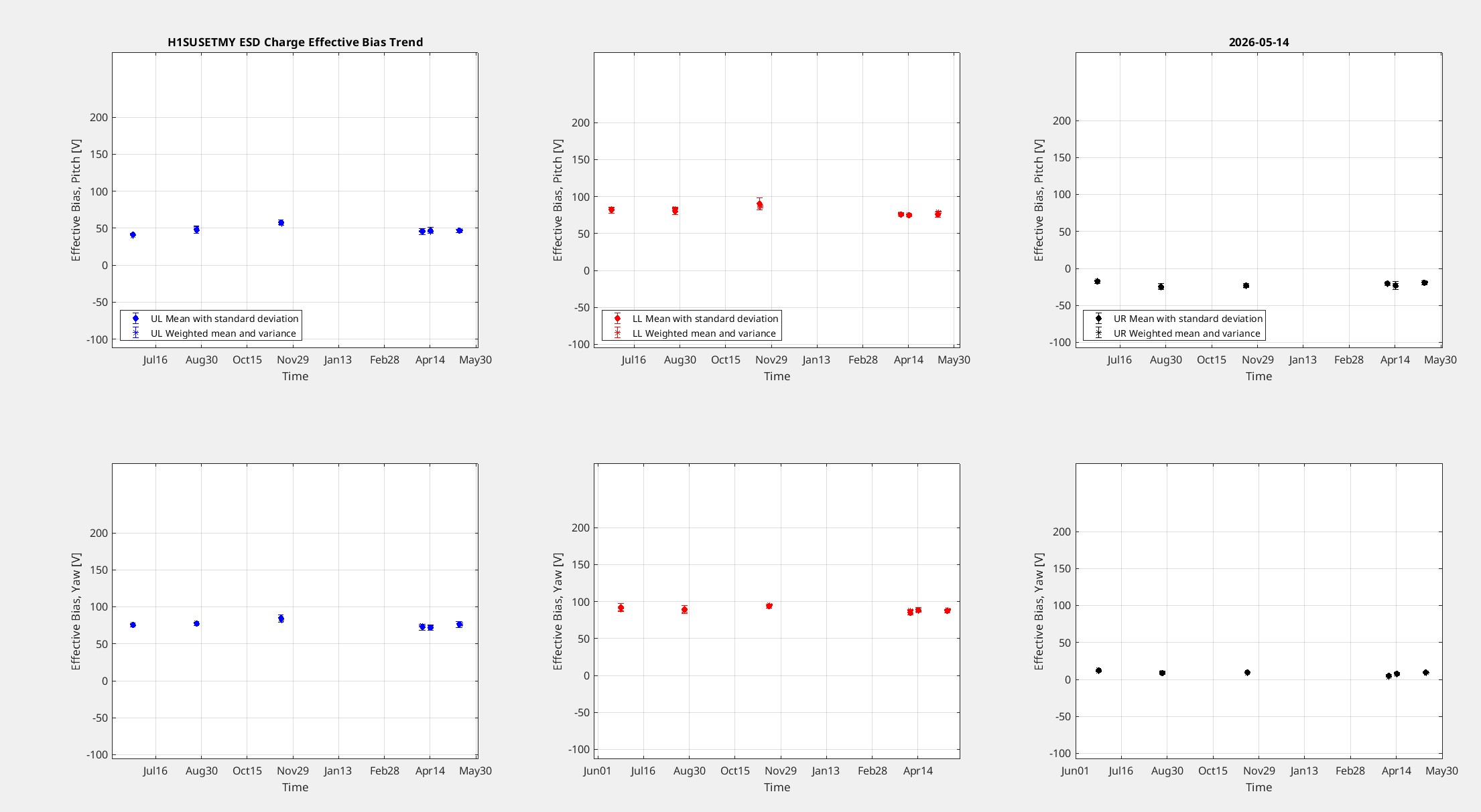
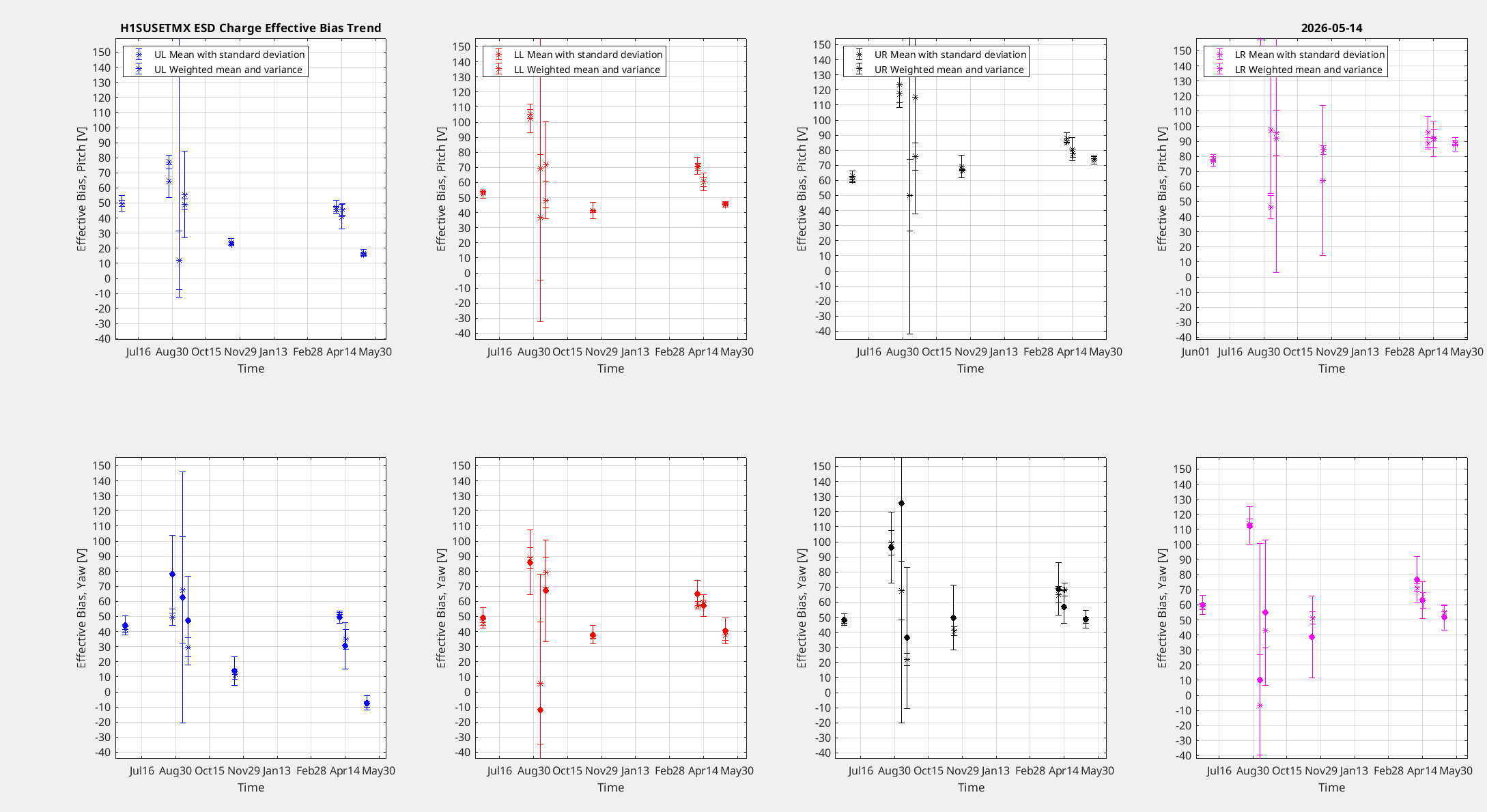
I ran the oplev charge measurements this morning for both of the ETMs, previously checked in alog89906.
ETMY's charge remains largely unchanged, the values across the quadrants remain below 100 on all quadrants/DOF and I don't see any appreciable trends. As a reminder we switched off the HV digitally for EY.
ETMX's charge is decreasing across all quadrants/DOF after the sign flip we inposed back in April. Over the past 4 weeks the average decrease for P was ~ -14 [V], and ~ -18.25 [V] for Y. UL saw the greatest decrease, a drop of over 30 [V] for both P & Y, UR saw the smallest decrease, around ~ 5 [V] for both P & Y. The charge is now at or below 50 [V] on all quadrants/DOF except UR_P and LR_P.
Ibrahim, Betsy, Randy
Today, we:
Particle counts were checked periodically and were under 75 consistently during acitvity
See pictures.


[Tom R, Oli]
Summary: QOSEM testing on the BSFM will require the tablecloth to be shifted OR SUSP to be raised, probably not worth the effort to do so given the BBSS will be ready for QOSEMs shortly.
Last Friday Oli and I attempted to install the QOSEMs onto the now removed from chamber and on test stand BSFM suspension, now that the IAS work was completed. The purpose of this test is to run and compare TFs taken with QOSEMs, providing a final functionality test before installation on the BBSS (which is not yet ready to accept QOSEMs). The full test and integration plan for the QOSEMs / BBSS can be found here T2600169.
We began by removing the SD BOSEM from M1 of the BSFM, and swapping the flag out for the QOSEM variety. We installed the QOSEM onto the cage, and used the existing DB25 in vac extensions and in air cables to run the QOSEM to its sat amp in SUS-R2. The QOSEM and its entire signal chain was functional, with readouts from this SD QOSEM appearing as expected in CDS.
Unfortunately upon unlocking the suspension, to align this SD QOSEM, we found that its y axis could not be brought into range with the cams (at its best was ~1mm off). This is a similar issues we faced when setting up the BBSS at LLO. As the SD BOSEM does not have a readout in this 'y' or vertical direction, misplacement of the tablecloth by ~1mm is unnoticeable, and does not impede function of the BOSEMs, but as we are activity trying to readout this axis it does matter for the QOSEM.
As such, to setup the QOSEMs on the BSFM, we would need to raise the tablecloth, or SUSP via the blade spring angle. While this certainly could be done, at the moment this feels like an unnecessary amount of work to do for a quick test of the QOSEMs, given the BBSS will be ready shortly. For now we have abandoned this test, and removed the SD QOSEM from the BSFM, reinstalling the original BOSEM.
Marc, Oli, Jeff, Jenne, Richard, Betsy, Fil, Keita, Rahul
Yesterday afternoon, Jenne pointed it to us that she was struggling to point (move in pitch or yaw) MC2 suspension in HAM3 chamber - she was applying bias on Pitch dof and was not seeing optic move accordingly (this was to get the beam in HAM2 for ISS PD work). We then started troubleshooting MC2. We started with the usual health checks (trying to damp the sus, TF measurements, M1 osem spectra) and it clearly looked that something was off - though we were not able to pin point on anything. Fil and I then swapped the cable 01 with cable 02 (basically trying to run MC2 using PR2 electronic chain for T1, T2, T2 and LF bosem - for ref. see wiring diagram D2300383, page 01 for MC2). When we (Oli and I) tried controlling MC2 using this, the results were all the more confusing.
This morning I restored the MC2 and PR2 cables back to its nominal state. Marc and I then started looking into the electronics chain of MC2 - poking each stage one by one. We started at Satamps (in the LVEA near HAM3 chamber) where I applied some offset at the CD on the medm screen and Marc measured the output voltage. For bosems T1, T2, T3, LF we measured 230mV and for RT and SD (these two bosems on MC2 share the electronics chain with PR2) we measured 350mV. We then moved to CER and repeated the same measurement at the MC2 coil driver and the result was no different. To check the DAC card and AI chassis we routed MC2 through another Coil driver (used by PR2) and yet there was no change in the output voltage. We swapped out the satamps and coil drivers to look for any change - found none. This meant that the electronics chain for MC2 was healthy, hence we restored everything.
Richard then suggested to measure the resistance of the coils on the BOSEMs at the satamps. For T1, T2, T3 and LF it was found to be around 16 ohms (much lower than what we expect) and for RT and SD 40ohms (which is the correct value). Around lunch time Marc and I talked to Jeff kissel and everything at this point was pointing towards the suspension (either the bosems or their connection at the new feed through) in Ham3 chamber. After lunch time Marc and I headed to HAM3 chamber. After looking at the dust count (measured in lower 10s), I opened the curtains on the +Y side near MC2. I then identified the M1, M2 and M3 stage cable on MC2 and followed it to the connector on the ISI table. I then followed the table cable to the feedthrough connection (in vacuum side). Marc was standing outside the chamber near the feedthrough side (in air). I then started unplugging the cables on each stage one by one and initially it was very confusing but very quickly we realized (to cut the long story short) that - the M1 and M2 stage cables were not correctly connected at the feedthrough (in vacuum side - see D1002874). To confirm this we measured the resistance of the bosem coils at the D6 feedthrough in HAM3 chamber. The top F1 and Bottom F3 connection were showing out 16 ohms and the middle F2 was showing 40ohms. This told us that the middle F2 connection belongs to the M1 stage and the top F2 belongs to M2 stage - see below for clarity.
Given below the flange layout in HAM3 chamber (D1002874)- D6 F1 and F2 were incorrectly connected. Marc and I changed that on in-air side.
Old connection - D6-F1 F DB25 SUS MC2 M1 T1T2T3LF OSEMs. New connection D6-F1 F DB25 SUS MC2 M2 OSEMs
Old connection - D6-F2 F DB25 SUS MC2 M2 OSEMs. New connection D6-F2 F DB25 SUS MC2 M1 T1T2T3LF OSEMs
Did not touch - D6-F3 F DB25 SUS MC2 M3 OSEMs
Oli took transfer function measurements and will post the results below. In the meanwhile we can say that MC2 is healthy and back in action.
Here is MC2 looking good after the find. I also took TFs of PR2 to check that it was also fine since we had been messing with it during the troubleshooting.
Betsy, Ibrahim
Today we:
WP 13235
WP 13169
Drawing O5 SUS HAM6 (sush6) System Wiring Diagrams - D2300379
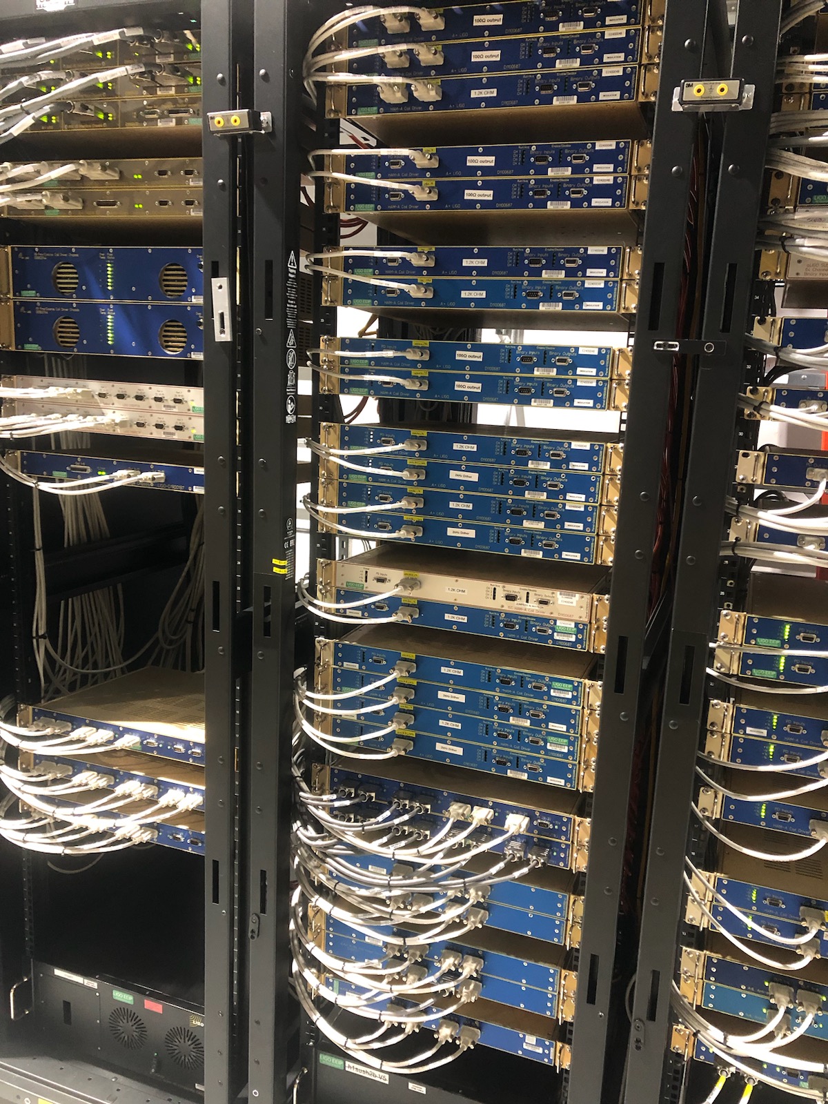
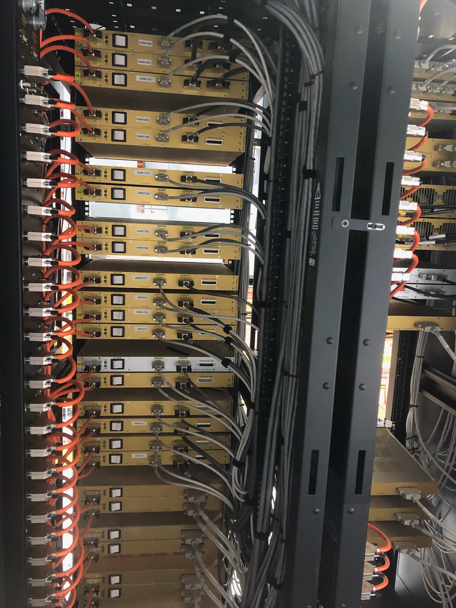
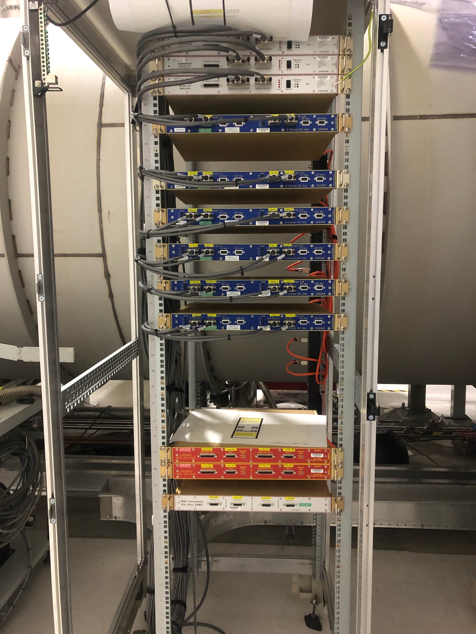
The O5 SUS HAM6 electronics and in-rack cabling installation in the MER is complete. System wiring diagrams D2300379 will need to be updated to show no IO h1susauxh6 was installed. New ADC cards (SUS AUX) were installed in the h1seih7 IO chassis.
IO chassis h1sush6 and h1sush7 share a 24V power supply. A dual Kepco power supply was installed to power the ±18V for SUS-M2. New electronics except the h1sush6 IO chassis were left powered off.
Status of the SUS-R7 rack is ongoing. All electronics installed. All long cables from MER and CER pulled and dressed. Rack requires ±18V and 200V for PSAMS. Depending on loads, plan is to use the SUS-R4 power supplies for the ±18V. The HV power supply will need to be placed on the HAM6 vacuum gauge interlock.
Ibrahim, Betsy
Today we:
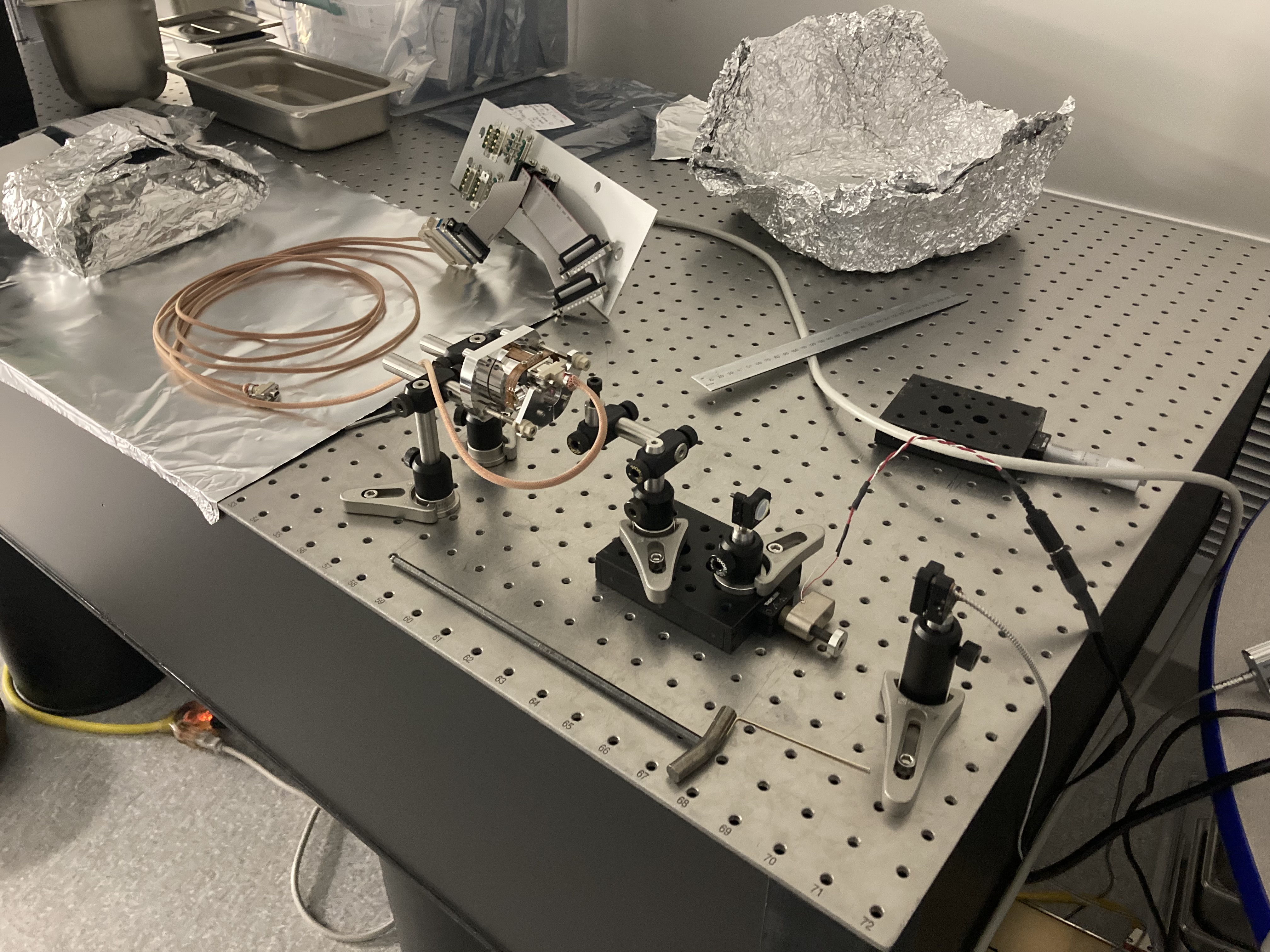
On Friday I setup the QOSEM calibration rig in the triple lab, in the staging building. It consists of a motorored translation stage (open loop picomotor), which drives the QOSEM flag into and out of the QOSEM body, while the sum and difference voltages produced by the sat amp are monitored. The position of the stage, and hence flag is readout by a Mach-Zender interferometer (SmarAct PicoScale). This is all controlled by a laptop running a python script.
The purpose of setting up this rig again is to better calibrate each QOSEM going on to the BBSS M1, by taking calibration data with the exact sat amp and flag that each QOSEM will use.
Today I finished setting up the QOSEM calibration rig in the triples lab. I grabbed the LHO production QOSEM sat amp from SUS-R2 for use in this calibration, and will match the flag and QOSEM pair to what they will be on the BBSS, such that the calibration is as valid as possible. The rig is all ready to go for calibration runs tomorrow.
[Tom Roocke, Oli]
Summary: The 6 QOSEMs and their signal chain for the BBSS are operational with the final sat amp, CER wiring, CDS mapping, in vac DB25 extension cables. All that remains to test before SUS installation is the duopus cables, which are in C&B currently.
In continuation from yesterday, we are testing out the QOSEM signal chain prior to installation of the BBSS. Yesterday we verified the sat amp was still functional and the readouts were showing up in CDS appropriately. See LHO:90072. Today we checked both the DB25 to DB25 extension cables, and the QOSEMs. To come is testing of the duopus cables, which are still in C&B.
DB25 Extension Testing:
Using a known functional Duopus cable (S2600215), and inair DB25, we tested the three DB25 extension cables by reading for the QOSEM coil resistance and diode drops at the in air DB25, where it connects to the sat amp. See the signal continuity test section in T2600170 for more information on this. All 3 cables are functional.
S2001548: DB25 working
S2100358: DB25 working
S2100410: DB25 working
QOSEM CDS Readout Testing:
Using a known functional Duopus Cable (S2600215), DB25 Extension (S2100410) and in air DB25, we checked for the open sum voltage in the CDS readout. This is the voltage seen on the sum channel of the QPD with no lens installed. Seeing a nonzero voltage here indicates that the QOSEM LED, QPD and signal chain are functional, but will be far lower than the operational sum level when the lens flag is appropriately focusing light onto the QPD. We tested the open sum voltage for all 6 QOSEMs designated for the BBSS. All QOSEMs and there signal chain are functional.
S2600008: working with open sum of 13910
S2600009: working with open sum of 14755
S2600010: working with open sum of 15550
S2600011: working with open sum of 15470
S2600012: working with open sum of 15348
S2600013: working with Open Sum of 14380
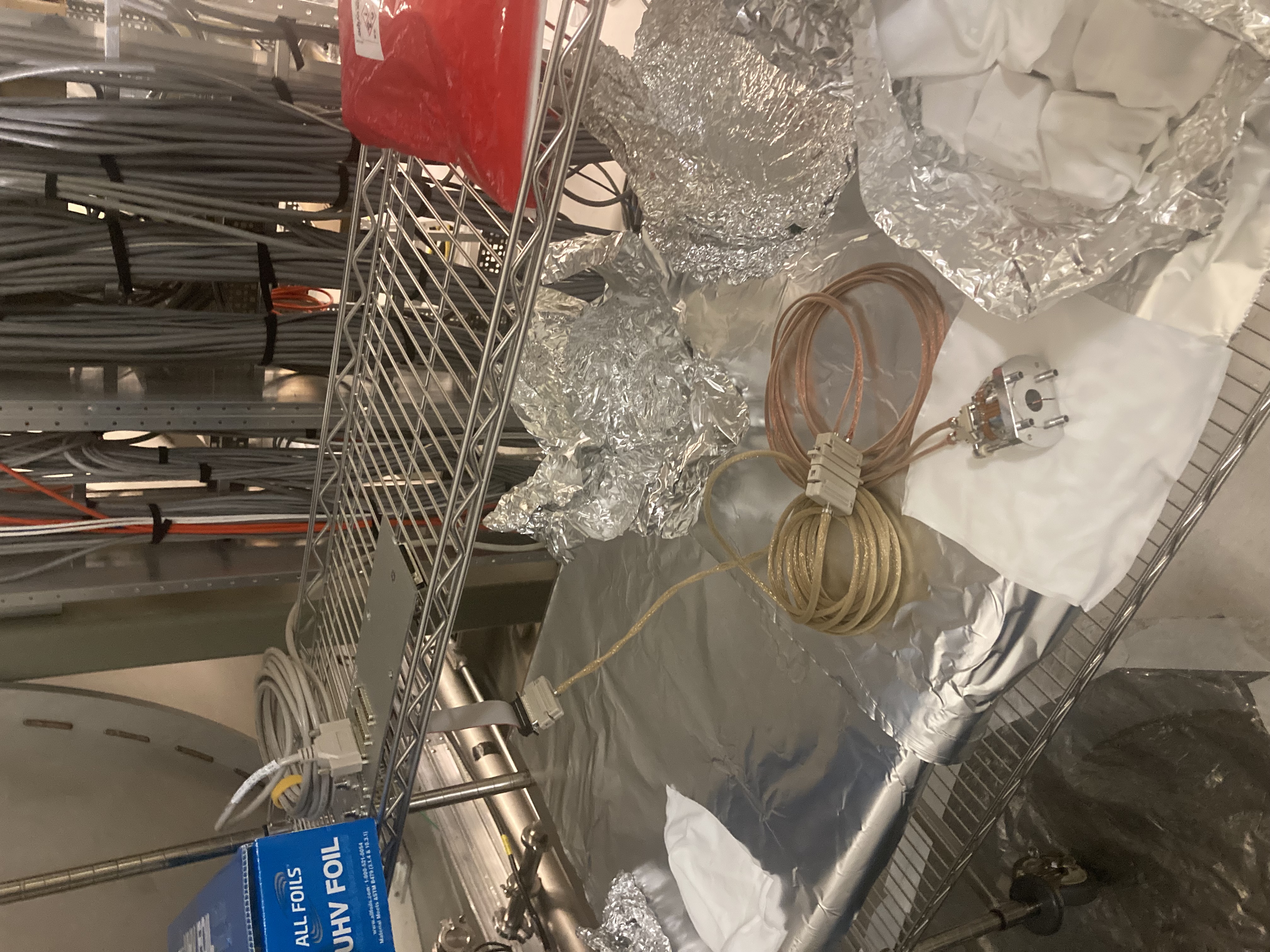
Today the QOSEM Duopus cable finished C&B, so I unbagged and tested them in the triples lab. I checked for continuty and any shorted pins with a multimeter, and all 4 cables passed. With this all parts of the QOSEM signal chain have been tested and ready to go for on suspension testing
[Tom Roocke, Oli]
Summary: QOSEM Sat Amp installed, run into ADCs and Coil drivers, injected signals into sat amp appearing where the should in CDS.
Yesterday the QOSEM Sat Amp was installed into the SUS-R2 rack (D2300383, LHO:90004), along with the in air DB37 wiring into the ADC. We checked that the signal routing into CDS was good, by injecting a current into the QPD inputs on the front panel. We used the portable calibrator found in the EE shop, to generate a 3.5mA DC current, which is about the expected level of photocurrent during nominal operation of the QOSEM. The negative output of the calibrator is connected to the cathode input for the QPD (pins 16 and 21 on the DB25 QOSEM inputs on the sat amp, see D2500300), and the positive output is connected to the anode inputs (pins 25, 12, 24, 11 and 20, 7, 19, 6).
We injected current into the anodes for all 6 channels in the sat amp, and all showed up in CDS on the expected channels. Next to check is the QOSEM Duopus cables, which we are waiting on from C&B. After which that should be the full signal chain tested.
a-Plus O5 SUS BSC2 HAM3 HAM4 (susb2h34) System Wiring Diagrams - D2300383
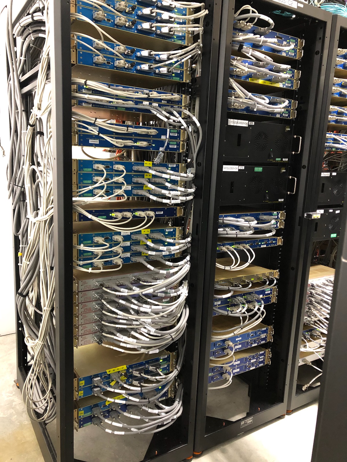
Electronics and cabling for BSC2 and HAM3 suspensions (BBSS, LO1, LO2) completed per D2300383. The new HAM-A and Triple Acquisition Drivers were left powered off (BS Bot, LO1, LO2).
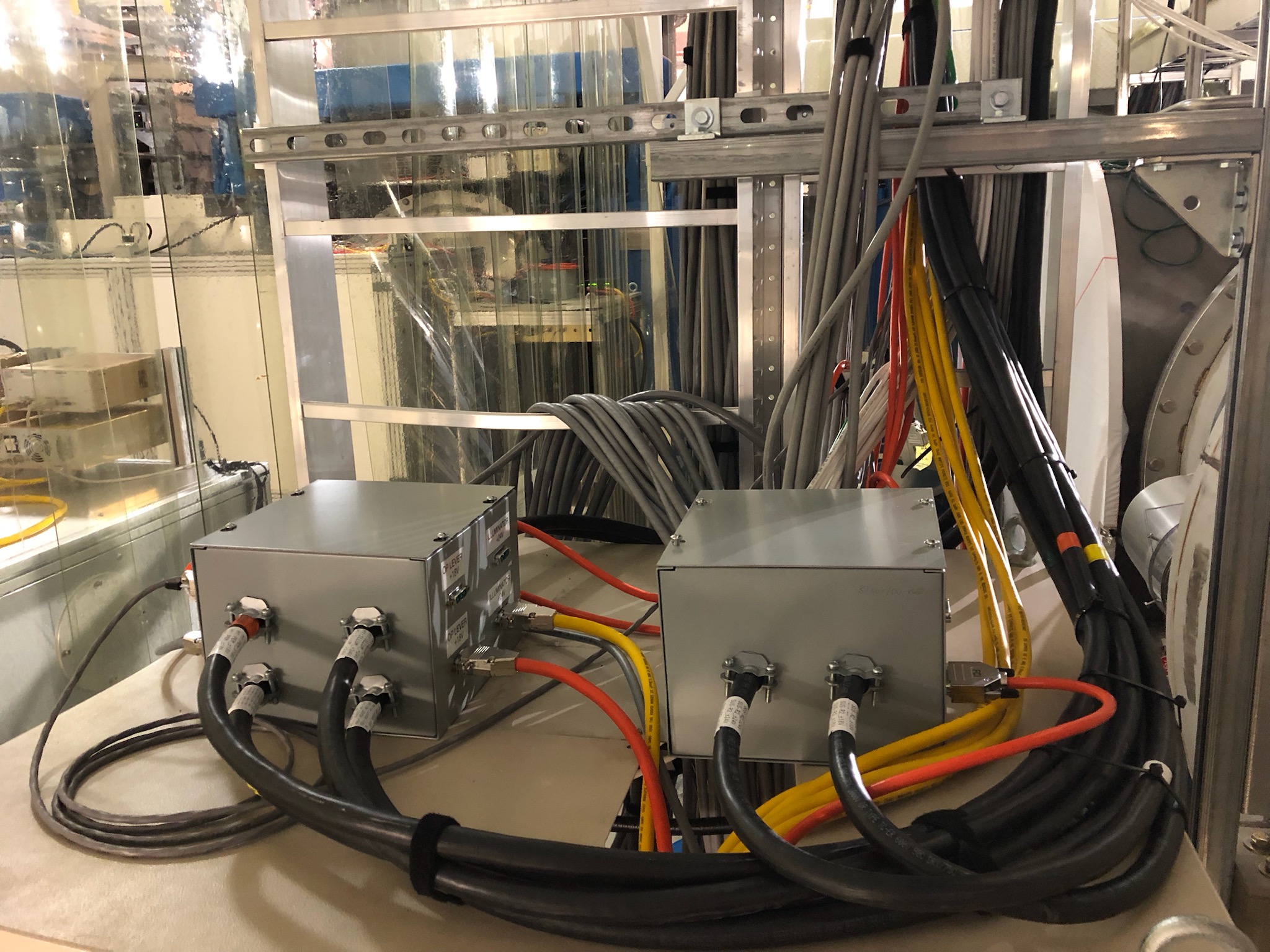
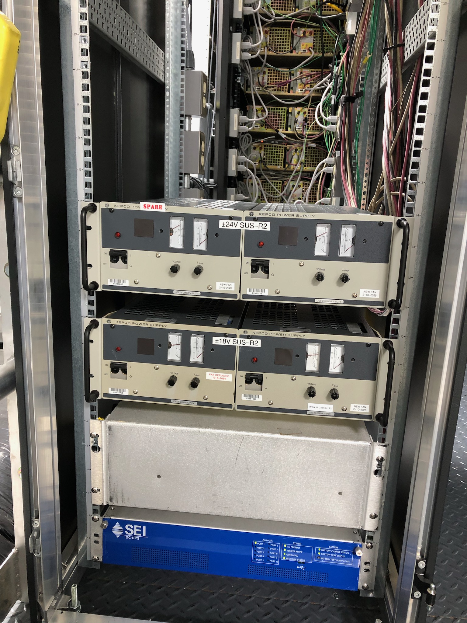
Four Kepco supplies were installed in the CER Mezzanine. Supplies provide power to the SUS-R2 rack. A second junction box was added to SUS-R2. They have been set to ±18V and ±24V, shared between SUS and SPI
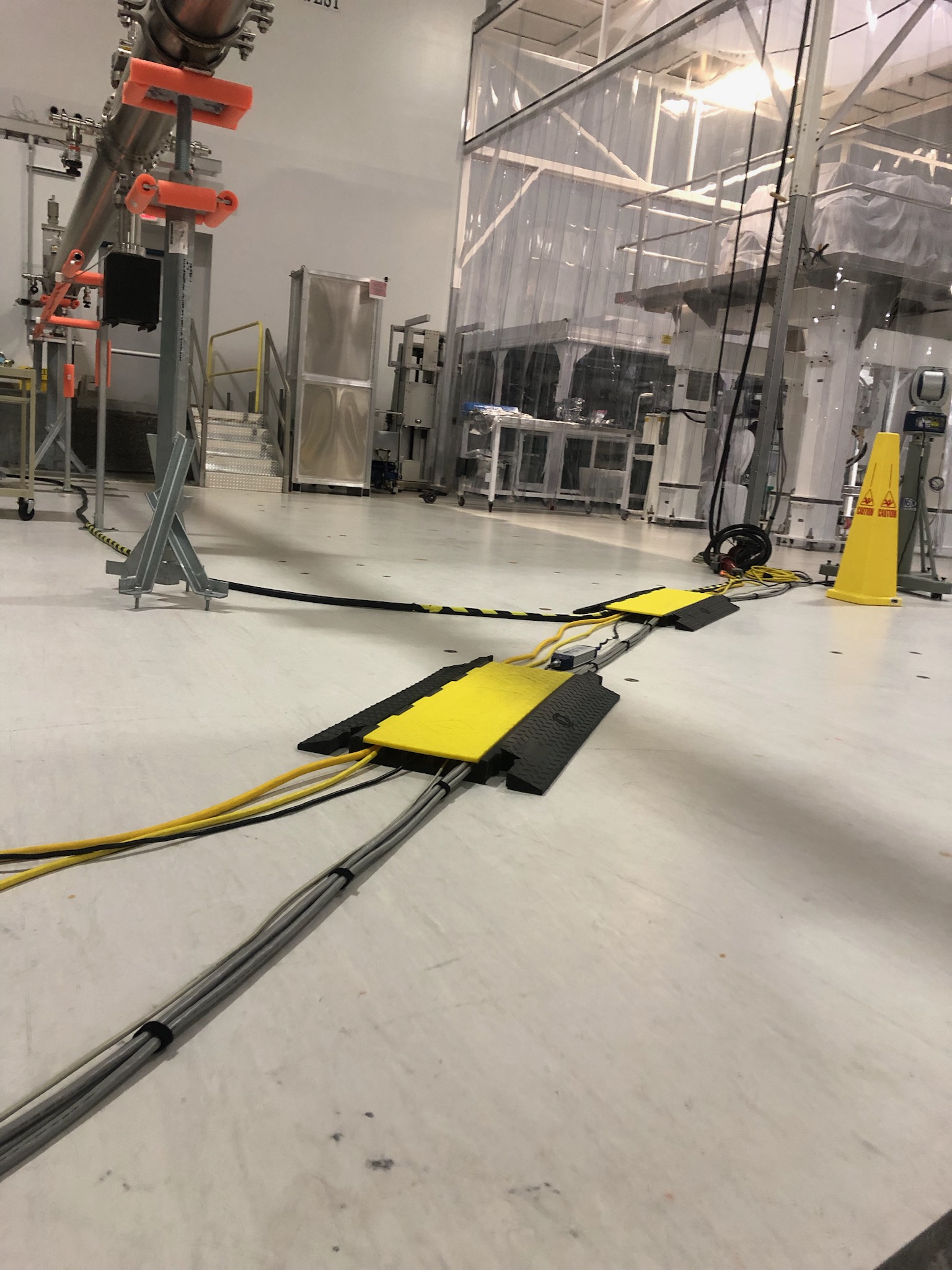
Final dressing of the field cables going from the biergarten to the West Bay Mechanical Test Stand completed. They will be used for testing of the old and new BS. Some cable swapping in the CER is required for testing the QOSEMs (some old BS electronics will be reused).
Mitchell, Rahul
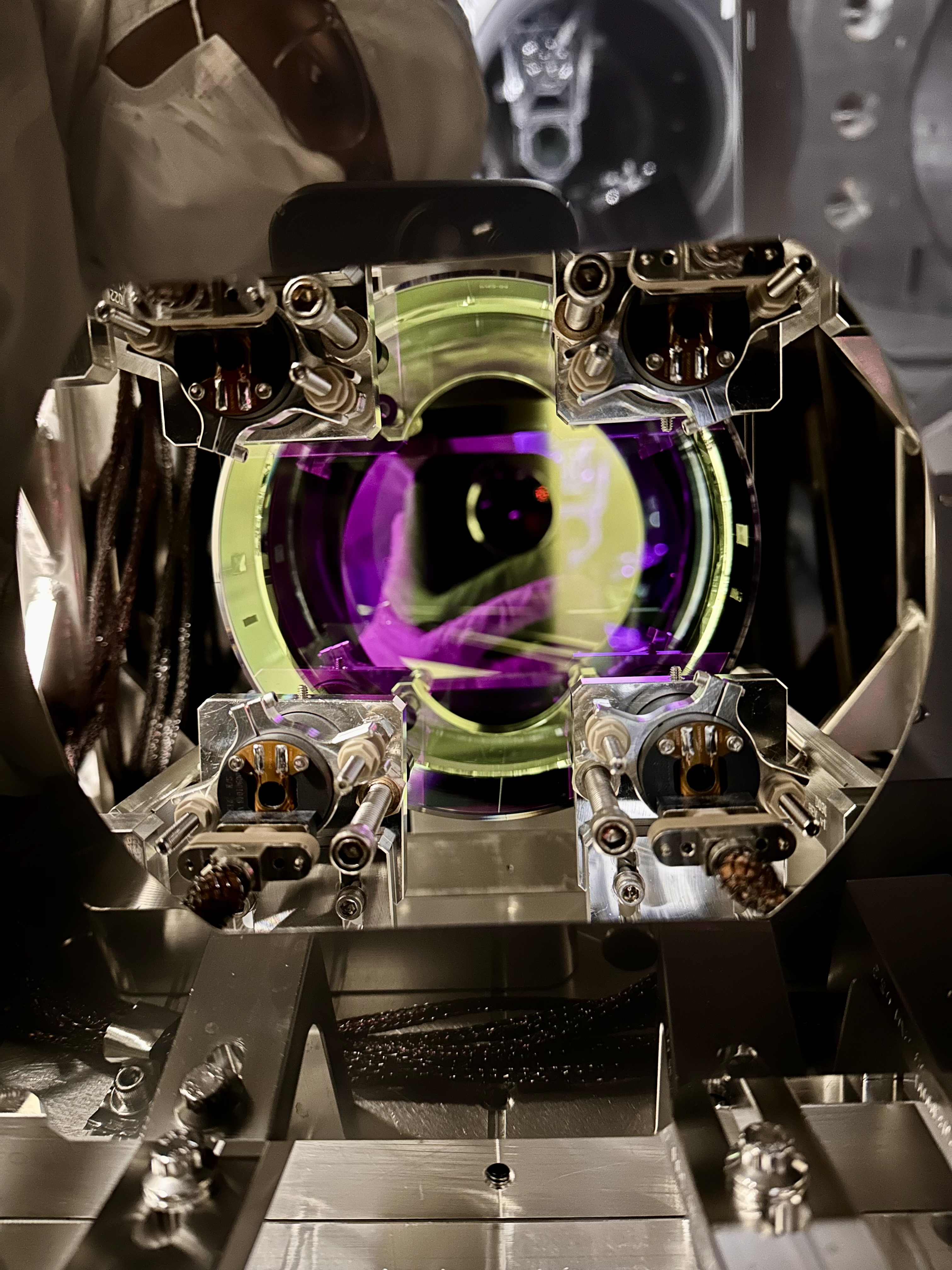
This morning we entered HAM3 chamber and attached the baffles (for stray light control) to both PR2 (HSTS) and MC2 (HSTS) suspensions. The baffle assembly design is shown D1700257_V5. These baffles were attached (directly mounted on the HSTS structure) on both the sides of the optic, i.e HR and AR side.
Before attaching the baffles I inspected both the optics and they looked nice and clean, hence didn't needed any First Contact cleaning.
I am attaching pictures below for reference.
We found that both PR2 and MC2 had two missing 1/4-20 threads on the HR side for attaching the mounting rail (D1700249_v1) of the baffle (Mitchell will attach a picture showing the same). Typically, these rail need four holes on the structure for securing them. However, we used the lower two threaded holes for attaching these mounting rail and they were rigidly secured. On the DCC I found that both PR2 and MC2 have D020023_V3 of the HSTS_Structural Weldment Assembly, latest D020023_V7 has more holes on the frame.
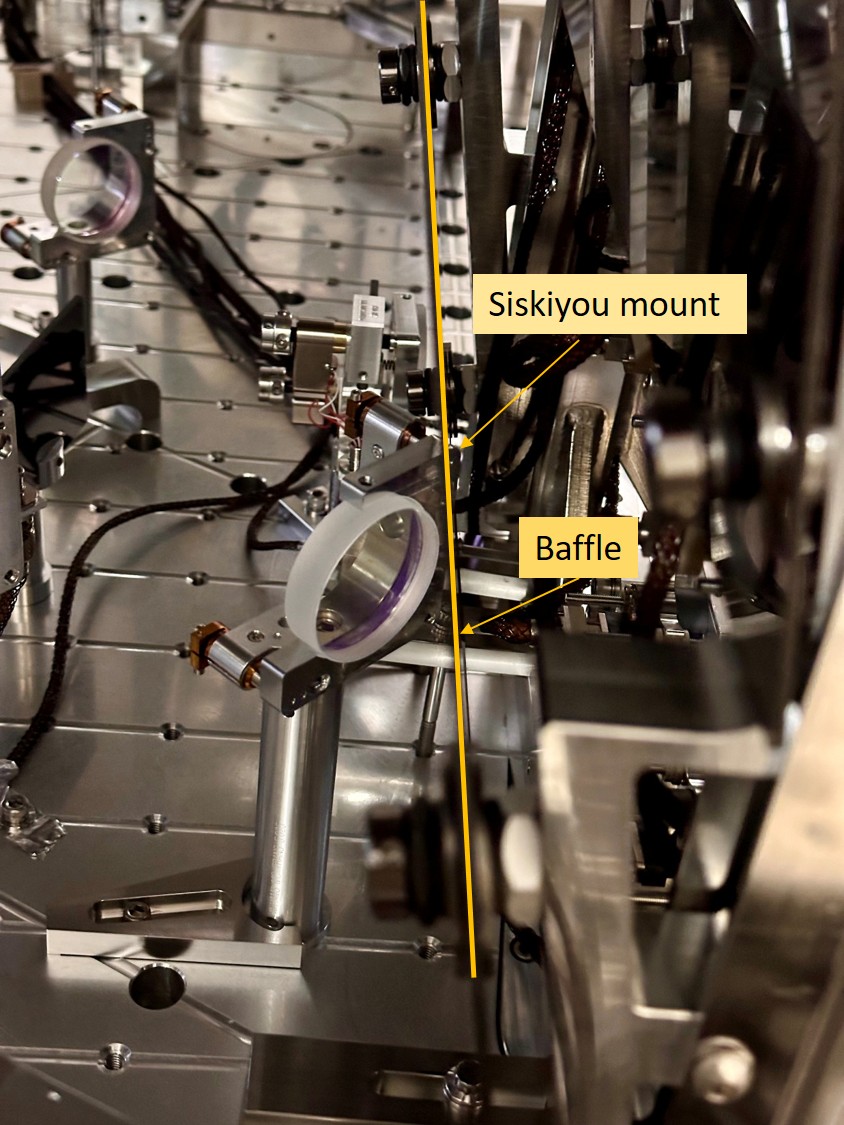
We also noted that one of the Siskiyou mount is very close to the MC2 baffle (AR side) as shown in the picture here. However, I can confirm that they are not touching and there is a decent amount of clearance between them.
I still need to perform health checks on both the suspensions to rule out any rubbing and will post the results as a comment over here.
Note - counts on dust monitor were in single digit before and after entering/exiting the chamber (Thanks to Ryan C for arranging this).
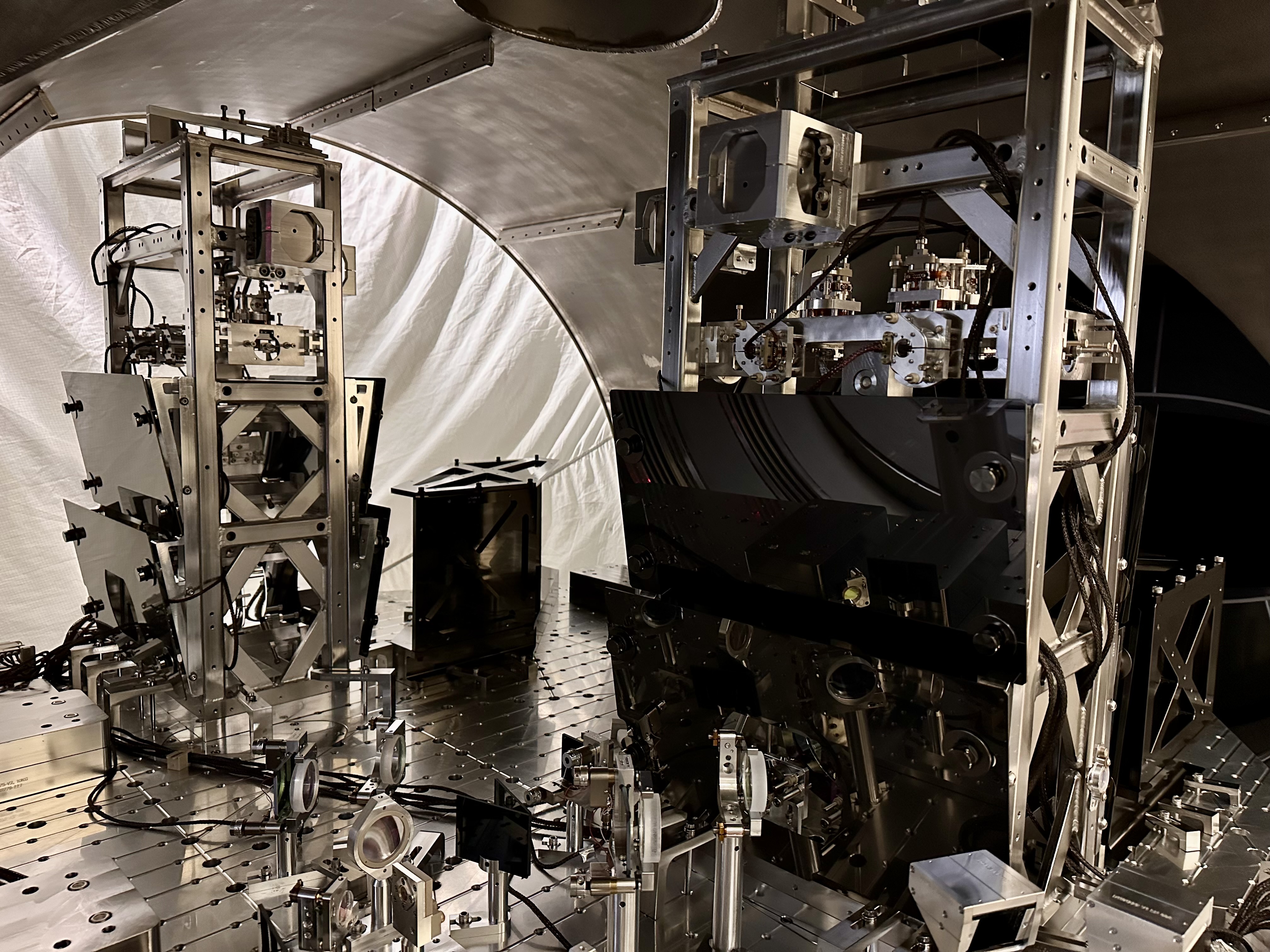
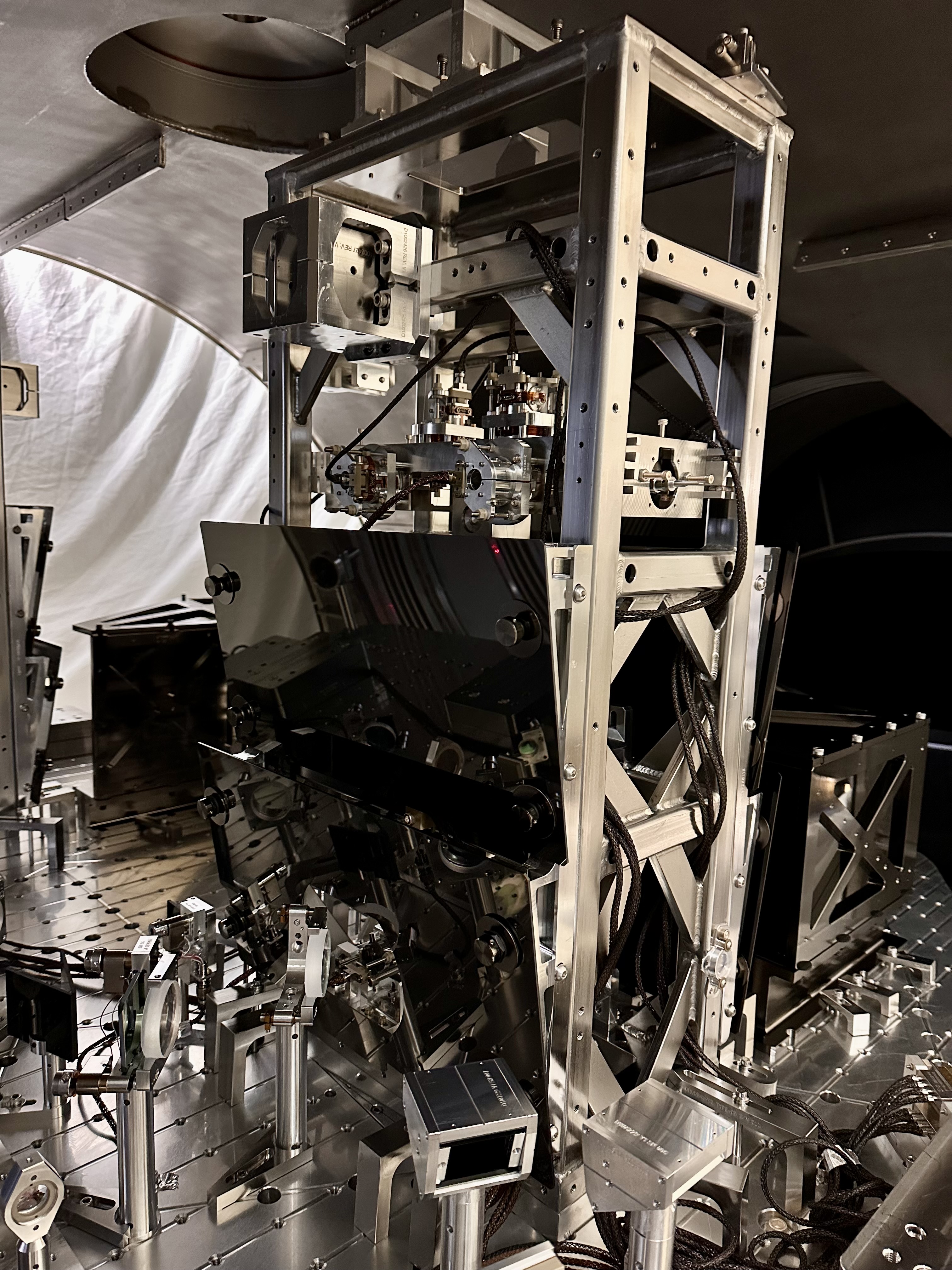
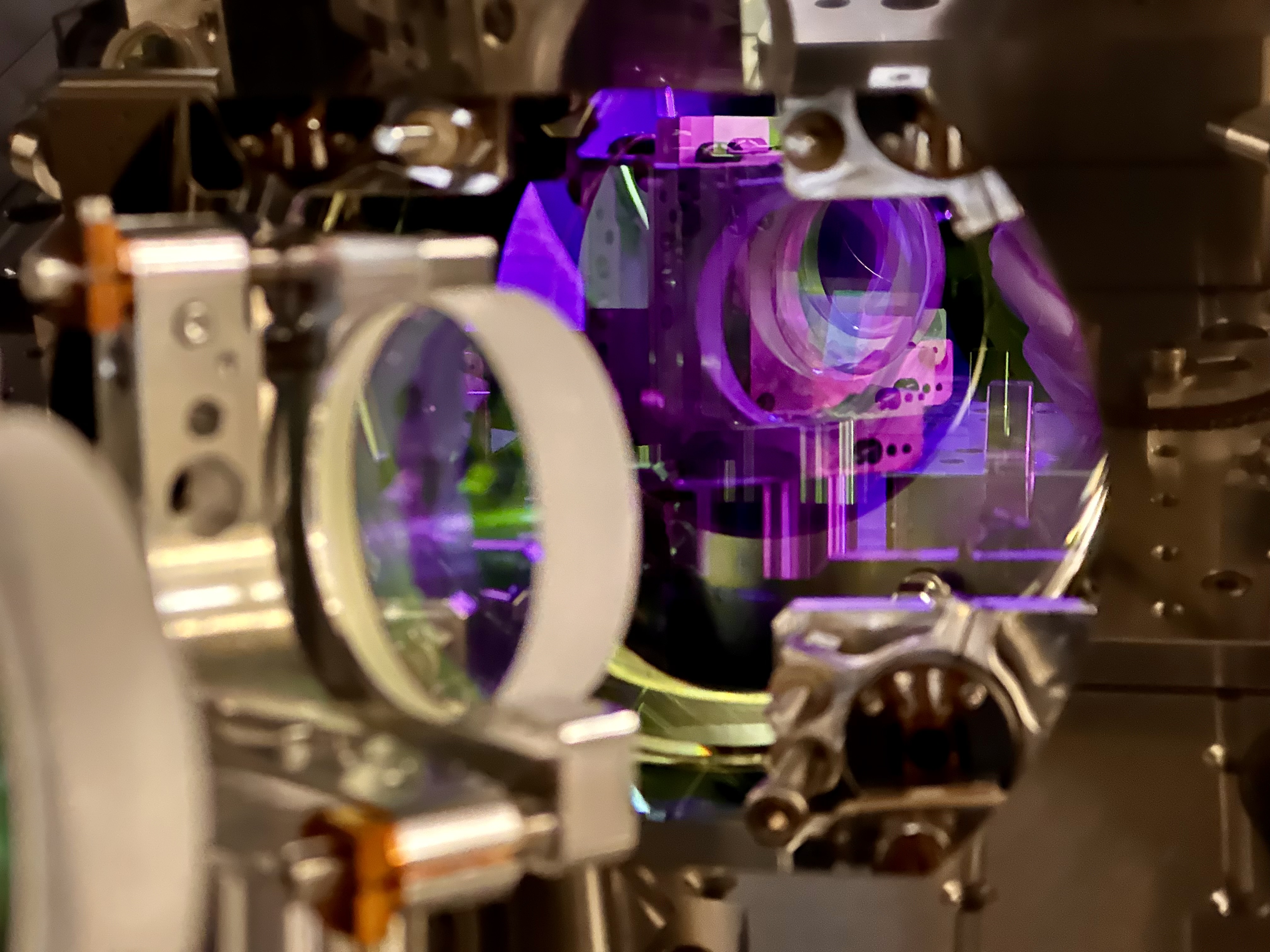
WP13211 closed.
Pictures of the HR side of PR2. No upper mounting holes for the HRST Baffle rail.

Note:- All the mounting holes looked centered and they aligned nicely and we found no issues (except the one mentioned above) during installation.
IIET ticket filed - https://services1.ligo-la.caltech.edu/FRS/show_bug.cgi?id=37761
As of 20:05 UTC, the cartridge from BSC2 (including the soon-to-be-decommissioned beamsplitter) has been placed on the test stand in the LVEA West bay. The cartridge was first lifted at 19:15 UTC before making its slow procession across the LVEA via the 5-ton overhead crane. More details and documentation to be posted later.
Today, with the BS SUS set to SAFE and the SEI chassis turned off at the rack, Tony, Ibrahim and I started unplugging and logging all of the cables in the chamber at the feedthrus.  I have a master log going which will be posted as an As-Built to the D1003079 BSC2 Flange Feedthru Layout Drawing for future re-plug-in activities.  Pictures of 2 feedthrus prior to unplugging are attached for samples of what I'm talking about.

As well, we dropped the ITMX Elliptical Baffle and Down Tube Sub assemblies from Stage 2 and have a good start on the ITMY one but didn't finish since it has mismatched hardware and we need a different tool.  (In the event we need to put them back up, we left them off to the sides of the chamber to deal with later - the ITMX one is the one closest into the ITMX chamber.)

Also also, we locked the BS SUS, tightened all of the nuts, removed all of the Vibration Absorber Cubes, and put the sock on the full SUS.

Tomorrow we need to:

Add the BS Face cover
Remove a Stay or 4
Finish stowing all of the dangling cables
Finish removing the ITMY Elliptical Baffle
Get on with the Support Tube and SEI work
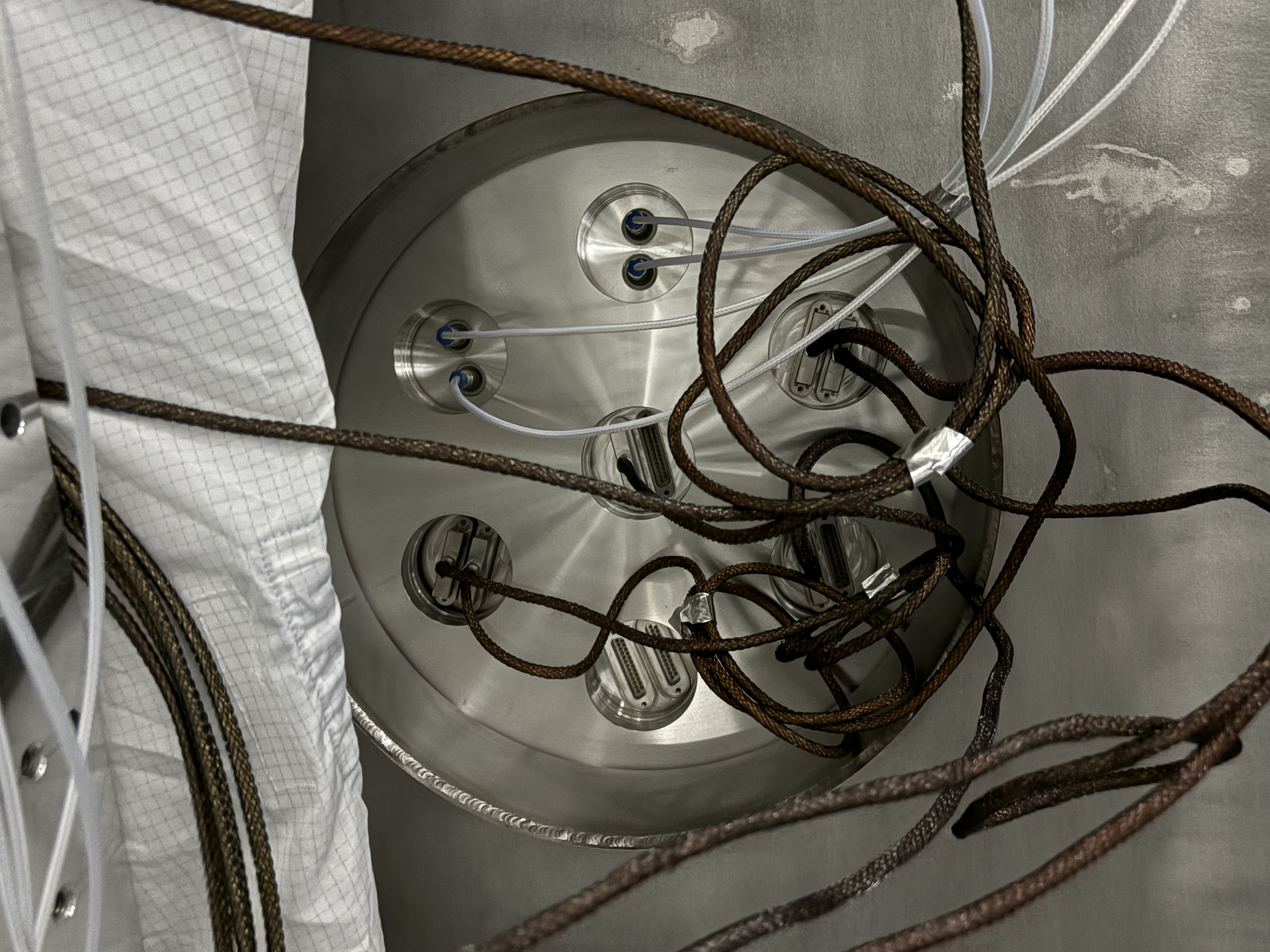
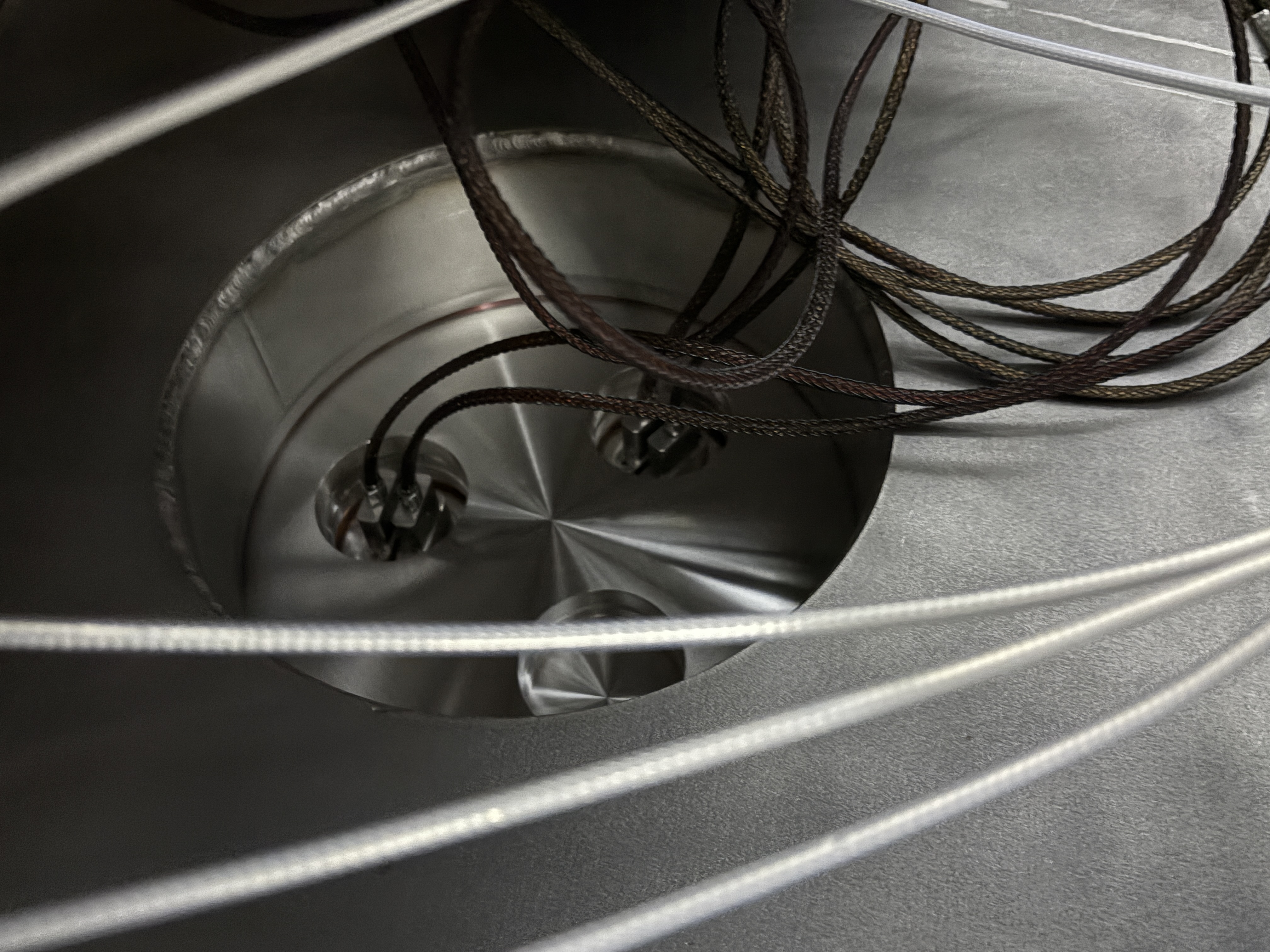
Here is a snapshot of the LHO BSC2 AS-BUILT cheatsheet of cable serial numbers, also posted as a google doc on https://dcc.ligo.org/LIGO-D1003079.
[Disha, Elenna, Keita]
Following FRS ticket 37601, we fixed the incorrect wiring of the OMC PZT cables. We determined that both OMCA and OMCB PZTs were wired incorrectly following this diagram D2200276. We found the black dots on the outside of each PZT to determine the positive lead. Disha and Keita noted that for OMCA, relative to the "head" of the manta ray (short side, this terminology is used in the build document T2100190), the PZT closest to the head has the black dot on towards the center of the manta ray, and the far PZT has the black dot towards the outside of the manta ray. For OMCB it is opposite, the PZT closest to the head has the positive lead on the outside, while the far PZT has it on the inside. I am specifically not naming PZTs 1 or 2, or LV or HV, because it was not clear to us which one is which.
We confirmed that the pins were in the wrong location on the cable, so Keita proceeded to swap the pins around.
The schematic diagram suggests there should be a shielding for the PZT cables wired to pin 1, but there was no such shielding on any pin.
OMCA:
far PZT: had pins on 1-6 (plus-minus), we moved these pins to 5-9 (p-m)
near PZT: had pins on 2-7 (p-m), we moved these pins to 4-8 (p-m)
OMCB:
far PZT: had pins on 1-6 (p-m), we moved to 5-9 (p-m)
near PZT: had pins on 2-7 (p-m), we moved to 4-8 (p-m)
We confirmed with a multimeter that there were no shorts between the pins after the pin swap.
J. Oberling, R. Crouch, J. Warner, B. Weaver, I. Abouelfettouh
This week we surveyed the position of the components that reside in WBSC2: The BS SUS cage (BSS), the ISI optics table (ISI Stage 2), and the 2 ITM Elliptical Baffles.
BS and the SUS Cage
The first picture shows our FARO survey of points on the BS SUS cage, chiefly along the bottom of the main support structure. These were surveyed by holding the FARO SMR against the hole being measured; the PolyWorks software handles the compensation from the center of the SMR to the point being measured. As can be seen, each point is very close in both X and Y axis position, being less than 0.1mm from its nominal location. The Z axis deviations are larger, but the largest of them is just over 0.25 mm, so every point is well within the positioning specifications used during installation and alignment in 2013.
Line 1 in the picture was created from the first and last survey points and represents the pointing of the BS SUS cage; all angles are reported in degrees. Some things to note here: I'm using the Acute Angle datum in PolyWorks, which is the angle measured from the closest axis. For the HR surface normal of the BS, the X Acute Angle is measured from the -X axis, the Y Acute Angle is measured from the +Y axis, and the Z Acute Angle is measured from the +Z axis. Since Line 1 is roughly perpendicular to the surface normal of the BS HR face, the axes the angles measure from are changed: The X Acute angle is now measured from the +X axis, the Y Acute Angle is still from the +Y axis, and the Z Acute Angle is now from the -Z axis. In addition, since Line 1 is nominally perpendicular to the BS HR surface normal I would expect the X and Y Acute angles to be swapped (BS X Acute = Line 1 Y Acute; BS Y Acute = Line 1 X Acute), but they aren't exactly. This appears to be a small error in the CAD model, if we make the assumption that the BS HR surface and the HR side of the BS SUS cage are nominally pointing in the same direction. This does, however, change the deviations for the X and Y Acute angles for Line 1. The table below shows what the data for Line 1 should be:
| Nominal | Measured | Deviation | |
| X Acute Angle | 44.9699 | 44.9073 | -0.0626 |
| Y Acute Angle | 45.0301 | 45.0927 | 0.0626 |
| Z Acute Angle | 90.0000 | 89.9661 | -0.0339 |
This means the BS SUS cage is yawed 0.0626°, or ~1.09 mrad, in the clockwise (CW) direction when looking from the top down (since Line 1 is closer to the +X axis than it should be). The Z Acute Angle represents a slight counterclockwise (CCW) roll of the SUS cage, when looking directly at the HR surface of the BS.
To attempt to better locate the BS in the IFO coordinate system, several measurements were taken with a ruler from points on the "Figure 8" section of the BS SUS cage to the BS optic itself. All measurments except one were done using a scale with 0.5 mm tic marks (so accurate to +/- 0.25 mm). The 10:00 "Figure 8 face to BS HR face" measurement had to be done using the side of the scale in inches, with 1/32" tic marks (so accurate to +/- 1/64") and then converted to mm (so accurate to +/- 0.4 mm). The measurements positions are listed like the BS HR surface is a clock, and assumes you are looking directly at the HR surface. The below table gives those results:
| Outside Edge of Figure 8 to BS optic edge (mm) | Front face of Figure 8 to BS HR face (mm) | |||||
| 3:00 (-X/-Y) | 6:00 (-Z) | 9:00 (+X/+Y) | 2:00 | 6:00 | 10:00 | |
| Measurement | 49.0 | 48.75 | 48.5 | 24.75 | 27.0 | 26.2 |
| CAD Nominal | 49.0 | 49.0 | 49.0 | 26.2 | 26.2 | 26.2 |
| Deviation | 0.0 | -0.25 | -0.5 | -1.45 | +0.8 | 0.0 |
The BS sits decently centered in the Figure 8 portion of the SUS cage, a little bit low and to the +X/+Y side. I would say not as much horizontally as it looks from the table, given the inherent error with reading the scale (the BS is not wider than its 370.0 mm specification, it's actually 0.15 mm narrower at 369.85 mm). The pointing implied by this measurement, however, is more than a little alarming. The 2:00 and 10:00 measurements show a significant yaw of the BS optic w.r.t. the SUS cage, and in the same direction as the yaw of the SUS cage as measured by the FARO. There is ~320.0 mm between the 2:00 and 10:00 positions on the BS, so that 1.45 mm difference in depth is a 4.53 mrad CW yaw. When added to the CW yaw of the SUS cage, this measurement shows that the BS optic is yawed 5.62 mrad CW from its nominal yaw. Even assuming the errors fall in our favor (so the 2:00 at 25.0 mm and the 10:00 at 25.8 mm), that's still a 3.59 mrad CW yaw (2.5 mrad BS and 1.09 mrad SUS cage). In addition, the 6:00 measurement implies a significant downward pitch of potentially several mrad, although with no way to measure the top of the optic we can't actually measure it. I have to be honest, I'm having a very hard time believing this measurement; we will revisit this once the BS cartridge has been moved to the test stand, where we have a better field of view for the FARO, more room to work and much better lighting around the BS, and can take direct measurements of the BS position and pointing using a total station and laser autocollimator (although there is no guarantee that the optic will be pointing in exactly the same direction after being craned across the LVEA). More to come on this.
ISI Optics Table
The second attachment shows the ISI positions as measured by the FARO. I've corrected the Z axis positions for the length of the rod we use to hang the SMR from the ISI so they give a better idea of the Z axis position. Not much can be said here, as LLO discovered that while these rods are good for measuring the Z axis position, they are not at all good at measuring X and Y. This makes sense as they were designed to be accurate in length and only length, so there's no guarantee that X and Y are repeatable. We plan on measuring the X and Y errors of this particular set of rods in the coming days (align to a table with a known hole pattern, attach the rod and measure with the FARO, repeat multiple times to see how the X and Y positions change). For now, we can say that the ISI is lower on the -X side vs the +X side, and lower on the +Y side vs the -Y side. I'm not alarmed by the deviations in Z axis position, as this ISI was supposed to be lower by ~2.5 mm (to place the BS in proper Z axis position, since it's lower in the IFO coordinate system but the SUS is the same length as the QUADs), but this was never captured in the CAD files.
ITM Elliptical Baffles
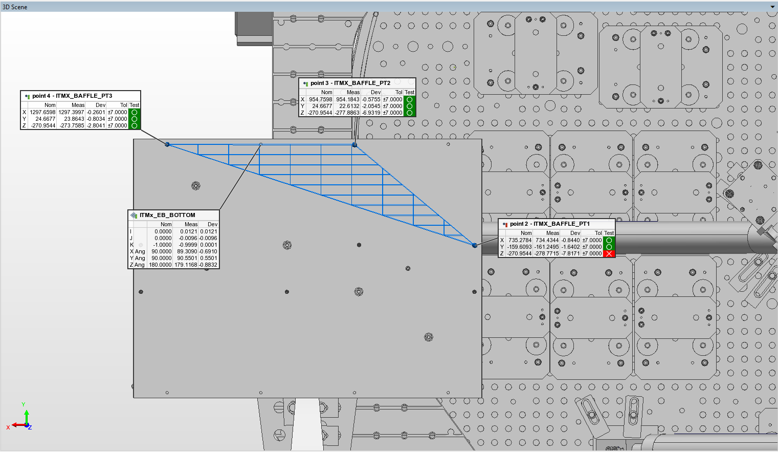
The final four attachments show our survey of both ITM elliptical baffles. Our view of the baffles and available fiducials to take measurements from were both limited, but we can say a few things.
ITMx Elliptical Baffle
We were able to get two points along the +Y bottom edge of the baffle, a single point along the +Y top edge, and single point near the center of the -X bottom edge of the baffle. From this I made a couple of planes that represent the +Y and bottom sides of the baffle and are shown in the third and fourth attachments; I, J, and K are the direction cosines of the surface normal of the plane, while the listed angles are the angle from the surface normal to the +X, +Y, and +Z axes. Interestingly, the point on the top edge looks very well aligned, within 1.0 mm all around, while the points along the bottom of the baffle are all low by several mm. In addition, there appears to be a significant upward pitch to the baffle. Jim did note that when attaching the transport bracket he had to push the baffle in the +X direction to clear ~0.5 mm at the point where the bracket attaches to the suspended portion of the baffle. This point is roughly 476 mm away from the baffle's suspension blade, so this is an ~1.05 mrad angle. Applying this same angle along the bottom of the baffle box gives an ~ -0.33 mm Z axis move of that bottom -X edge of the baffle, so this does not account for the measured deviation. In addition to the pitch, the bottom plane also shows a large roll (CCW when looking at the ITMx in WBSC3), while the side plane shows a large yaw (CCW when looking from the top down). We know these baffle panels aren't exactly straight, so it's hard to say if this significant pointing is also present on the elliptical hole of the baffle (we couldn't see it, so we couldn't measure it directly).
ITMy Elliptical Baffle
Similar to the ITMx baffle, we were only able to get a handful of points along the -X side and the bottom of the baffle. I made planes from these points representing the -X side and the bottom of the baffle (fifth and sixth attachments). As seen with the ITMx baffle, the points along the top of the baffle all look good while the points on the bottom are too low by several mm. There is a significant upward pitch to this baffle as well, as well as a large roll (CCW when looking at ITMy in WBSC1) and yaw (CCW when looking from the top down), although none are as large those as seen on the ITMx elliptical baffle. Again, we could not see the elliptical hole in the baffle to measure it, so we can't say if this pointing is an artifact of the panels or also present on the actual baffle portion of the baffle.
This completes our in-chamber measurements of the WBSC2 cartridge assembly, and closes LHO WP 13171.
I also want to note, Ryan and I also preformed some in-chamber FARO measurements in WHAM3 (ISI, MC2 SUS cage, PR2 SUS cage, MC2 and PR2 baffles) on April 10th; I will post those as soon as I get a chance to process the data in PolyWorks.




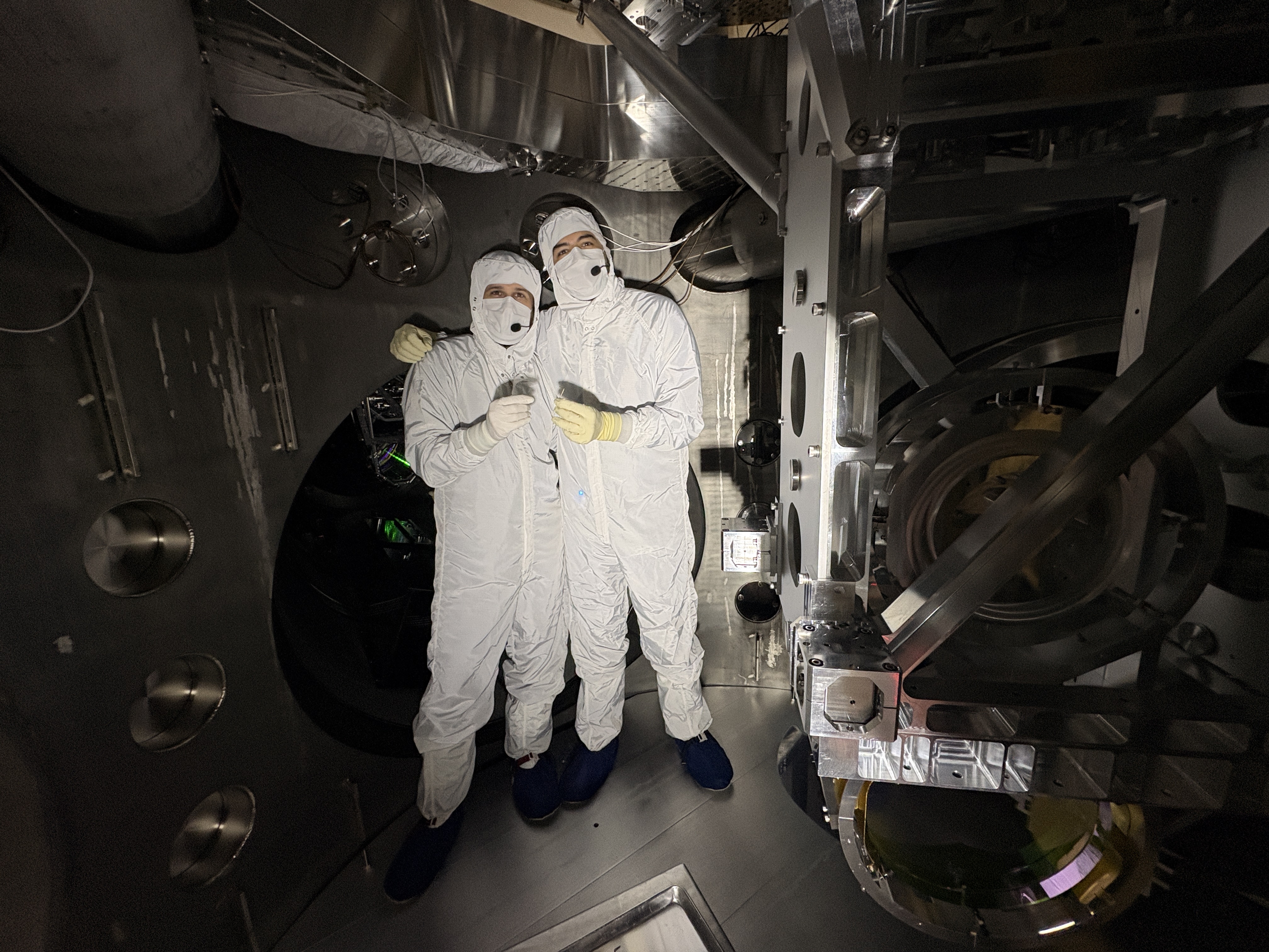
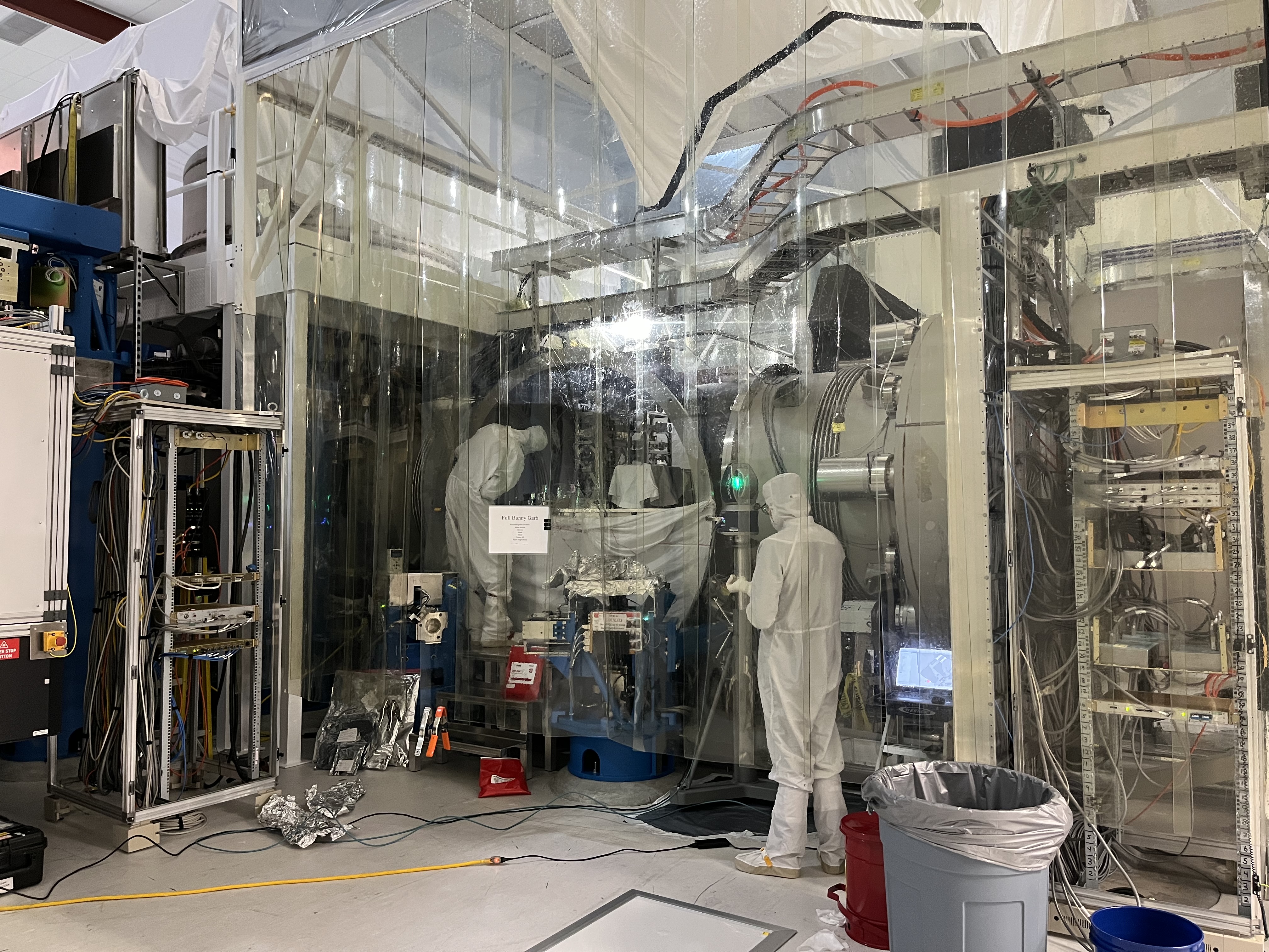
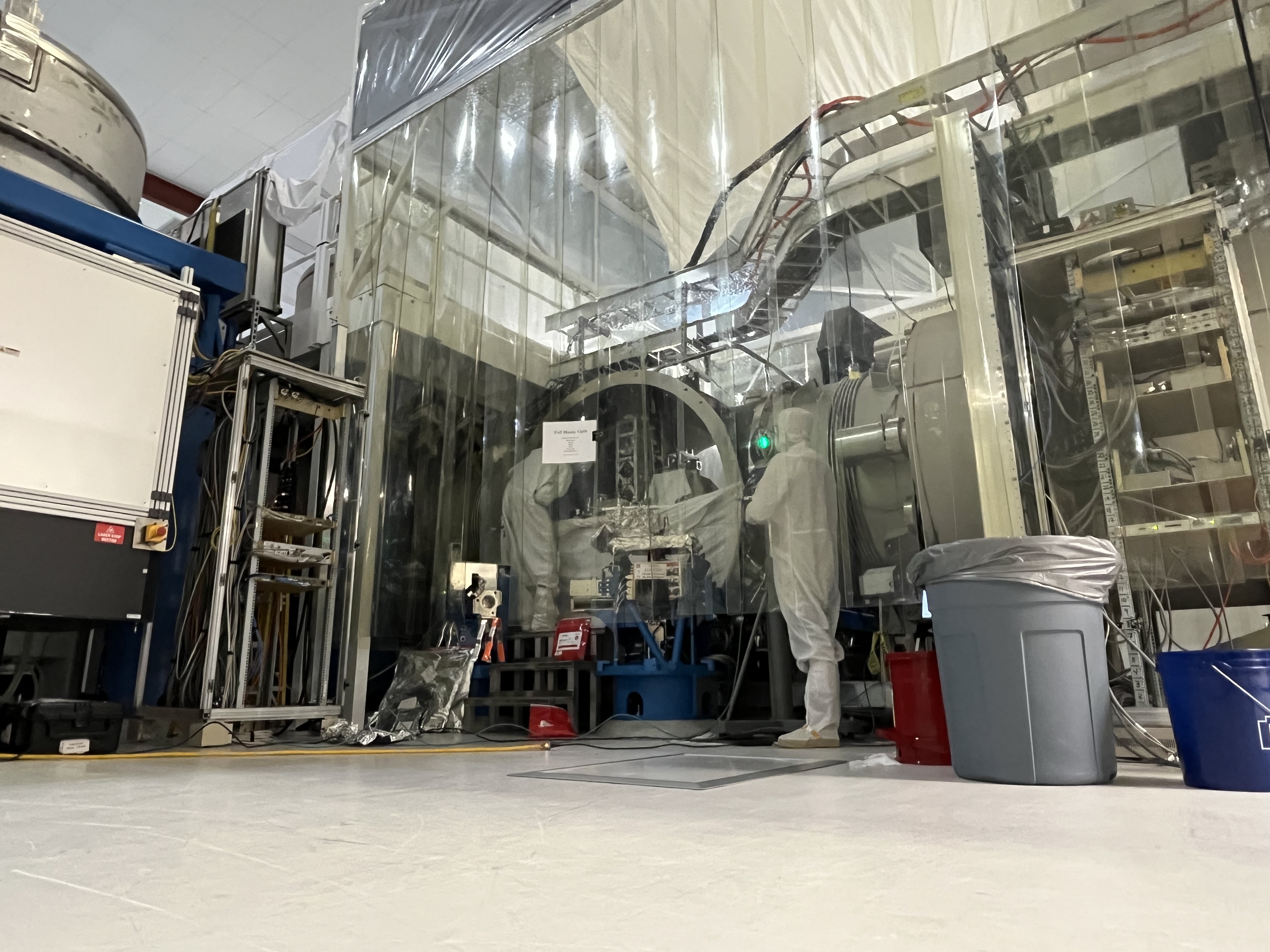
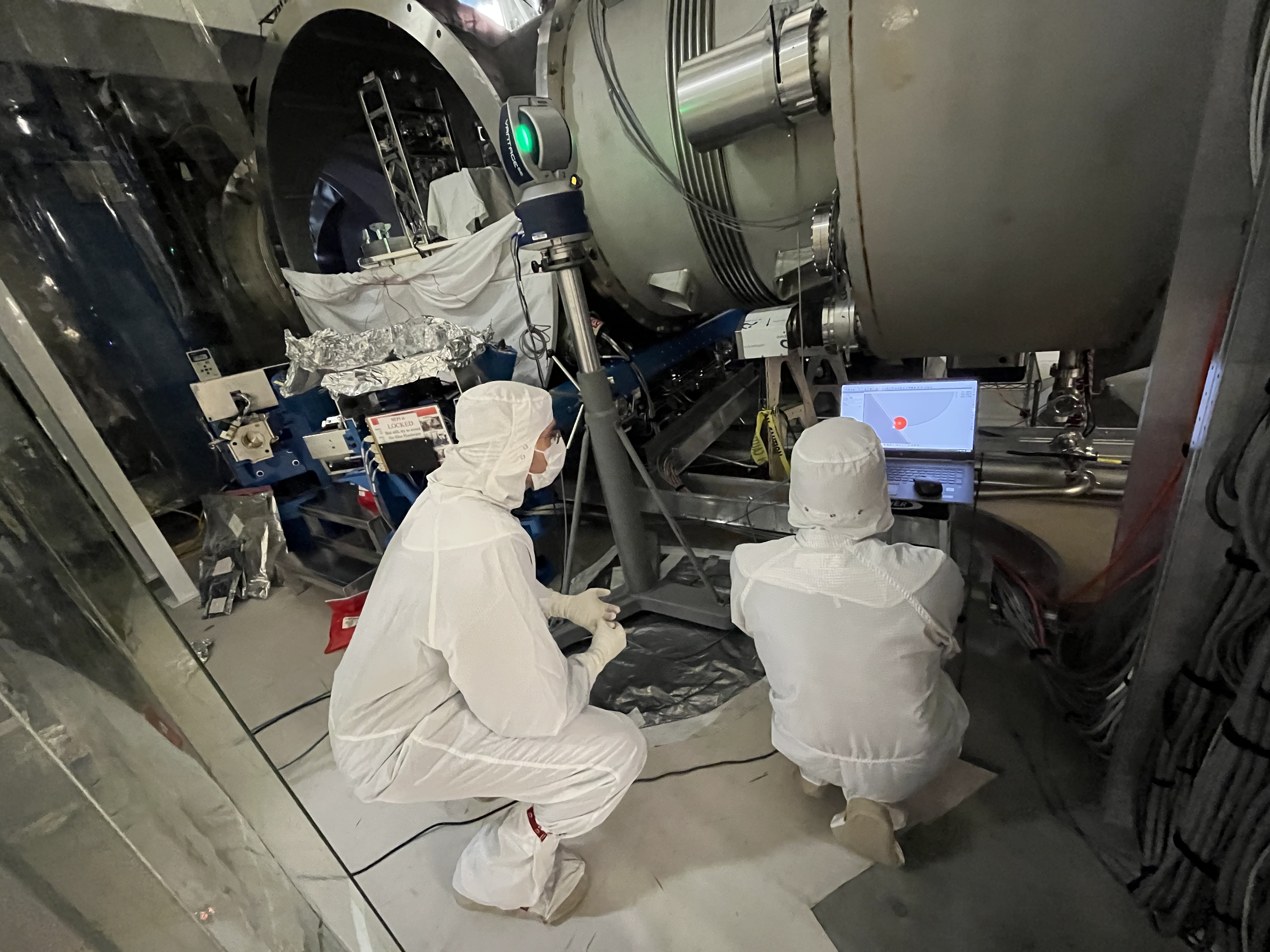
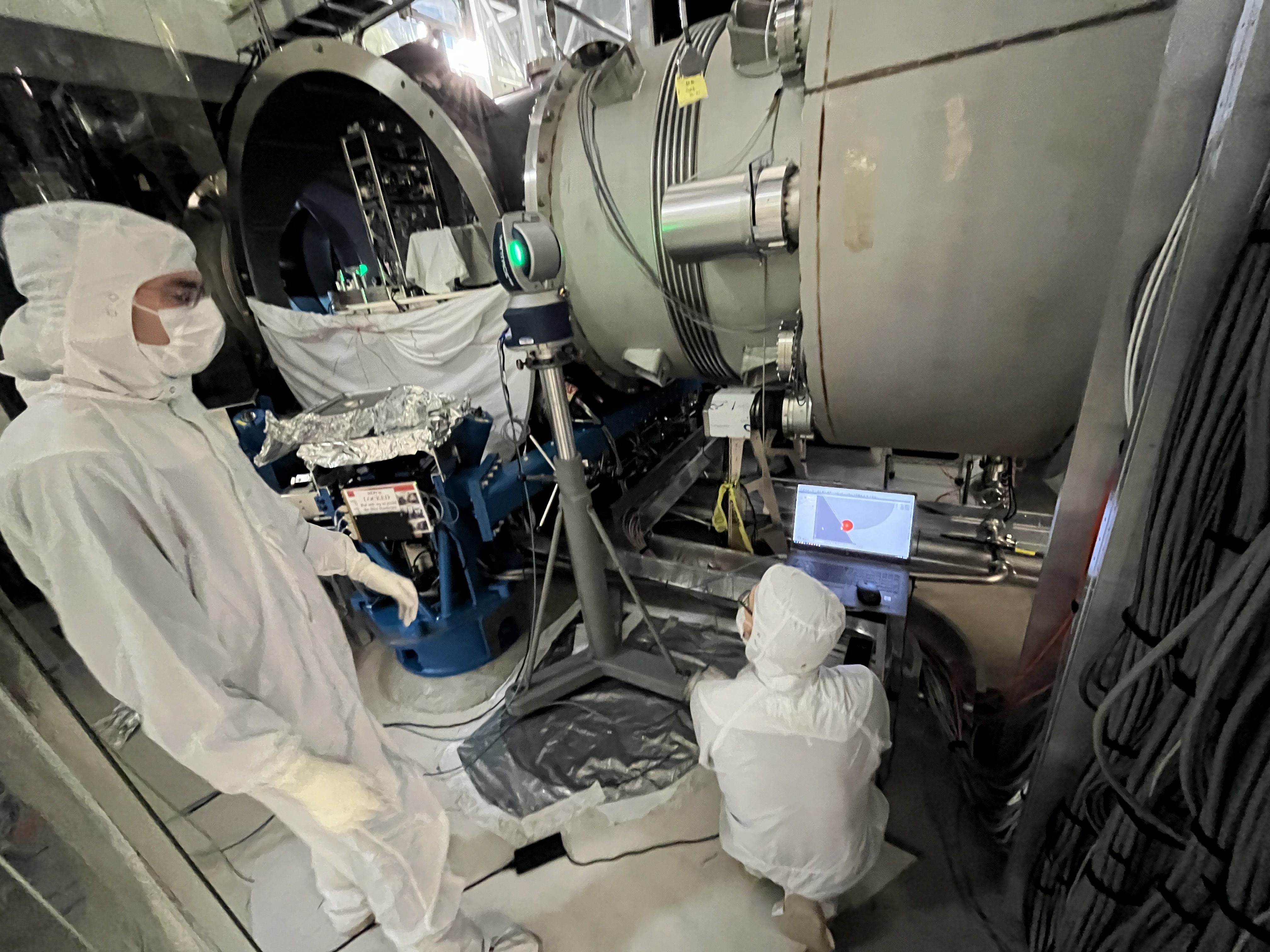
Some action photos while Jason & RyanC were chamberside at HAM3.

Ignore the very first table in the above alog, concerning the yaw of the BS SUS cage, as I apparently forgot how to do math when creating that. In writing a master alog trying to tie together the series of measurements we took on the BS (still a WIP) I went back to PolyWorks and, in a separate file so to not compromise the existing data, rotated the CAD model so the HR face of the BS SUS matched the target yaw of the BS HR surface. The results of that are shown in the attachment here. The angles listed for Line 3 are measured from the positive axis; i.e. X Ang is measured from the +X axis. Takeaways: