I've looked at the OMC length noise. A factor of 30 increase in RMS is enough to create broadband noise with a slope of 1/f^2 below 200 Hz. Based on predictions for the noise without any excitation on, it seems like OMC length noise should not be limiting DARM at low frequencies.
Relevant alogs and documents: 19212 18034 G1100903 Section 5.4 of Dan Hoak's thesis
Estimating OMC length noise
To get an out of loop measurement of the OMC length fluctuations at high frequencies, I used the method described in the above documents, with a few changes.
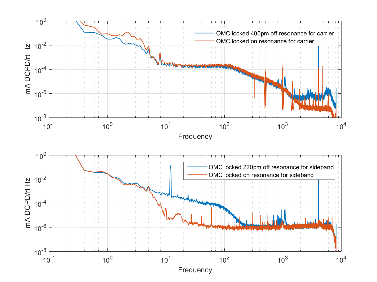
With the interferometer locked at 2Watts, before transitioning to DC readout, I locked the OMC on both the carrier and sidebands. The first attached figure shows DCPD power spectra with the OMC locked both on resonance and somewhat detuned. With the OMC on resonance, the coupling of OMC length to transmitted power should be quadratic, so the orange on resonance traces show us the level of intensity noise that is the noise floor of these measurements. With the OMC slightly detuned, a linear coupling from OMC length is introduced, so at frequencies where the blue detuned traces are above the orange, we have made a decent measurement of OMC length here. A few quick points:
- The OMC angular controls should be switched to the QPDs for this measurement, and the DARM boost on.
- It is best to make the measurement for the carrier with the full interferometer locked to take advantage of the IFO's intensity noise filtering.
- The measurement made locked on the carrier is also sensitive to DARM, so the shot noise imposed on DARM by the RF DARM loop dominates the noise up to 2 kHz. If necessary we could try to improve this measurement by reducing the bandwidth of RF DARM, but it seems adequate as is.
- For the sideband measurement, we have to turn the ISS 2nd loop gain up to match what we would have at 50 Watts (there is no gain scaling with input power for the current generation of ISS, so to emulate the loop shape at 50 Watts when locked at 2 Watts: turn of the AC coupling, turn the gain up by 30dB, and engage the 2 boosts. Reverse order to undo before powereing up) The noise is then limited by the shot noise of the ISS second loop, so this measurement could possibly be improved by doing it at 50 Watts single bounce.
- I made the detuned measurements using the dither lock for OMC length, and put offsets in the servo, not by using the side of fringe lock used before. This means that the side of fringe measurement is out of loop, and we don't have to worry about correcting for the loop gain. It also means that you cannot lock at a half fringe. I didn't want to try to write math in the alog, so the attached PDF shows how to find the fringe offset and calibrate the side of fringe measurements for any offset.
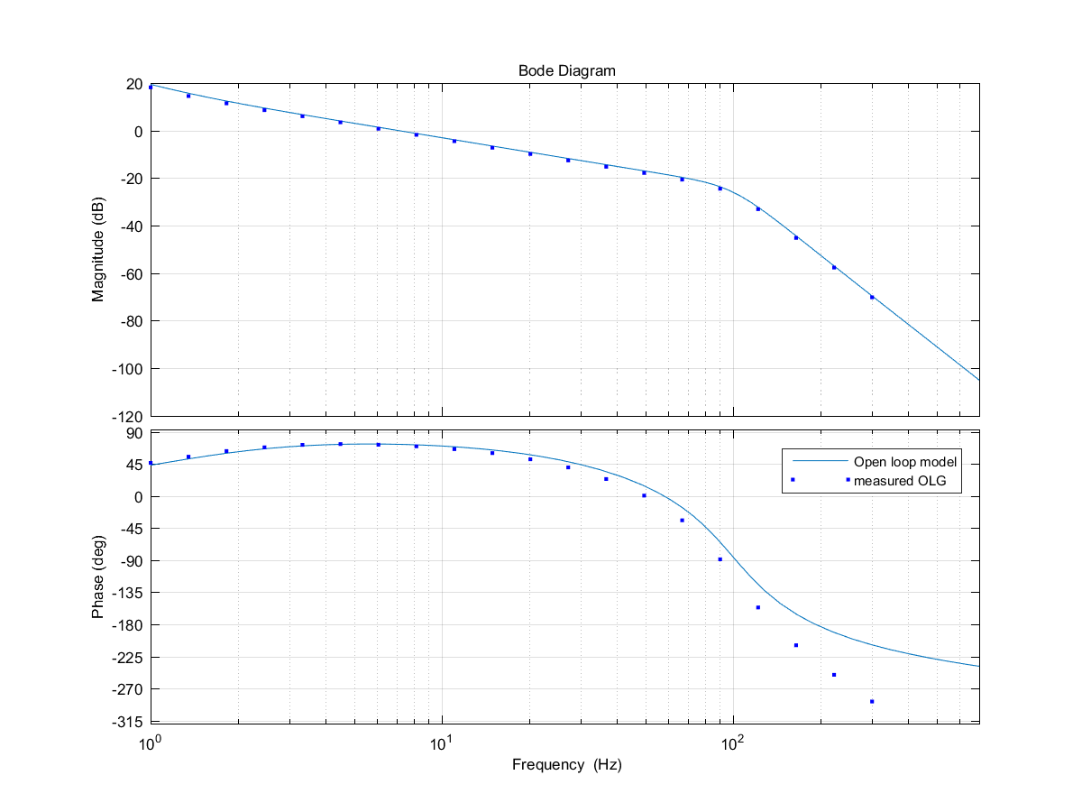
At low frequecies, I used the in loop error signal to estimate the OMC length noise. The equation for the optical gain of the dither loop is in the attached PDF, I used a dither amplitude of 0.8pm (there is a fudge factor here). The dither loop is currently not shot noise limited, because we have large frequency noise in DARM around the dither frequency of 4100Hz which changes over hours times scales. To estimate the length noise imposed by the dither loop, we need a model of the loop gain, shown in the second attached png (thanks Koji for the PZT model). For frequencies where the error signal is dominated by sensor noise, the estimate of the actual length noise is measured error signal*OLG/bandpass filter upstream of demodulation, where it is dominated by real length residual we can just use the measured error signal (ignoring the bandpass).
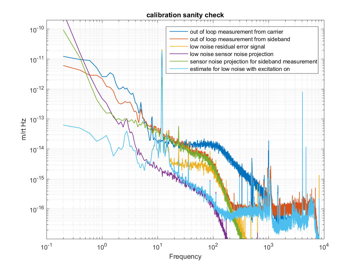
The third attached PNG shows the four different ways of estimating OMC length noise (carrier side of fringe, sideband side of fringe, sensor noise from dither error signal, residual length from dither error signal), so you can see how the calibrations agree. I've shown the projection for sensor noise when we are locked on the sideband, which is higher than in low noise, so that you can see that it agrees with the out of loop sideband measurement fairly well. Most of the measurements here were taken with a 1 count exctiation to PZT2 at 12 Hz. At 12 Hz, the low noise residual error signal should agree with the out of loop sideband measurement, but there is about a factor of 2 discrepancy. The closed loop supression for the 2 cases are similar to within 1dB, so changes in the loop gain don't seem to explain this discrepancy.
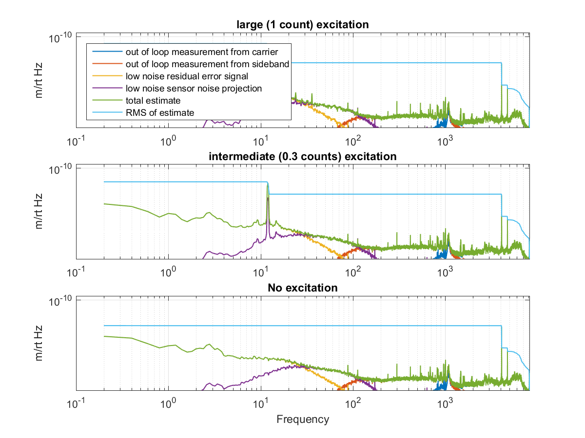
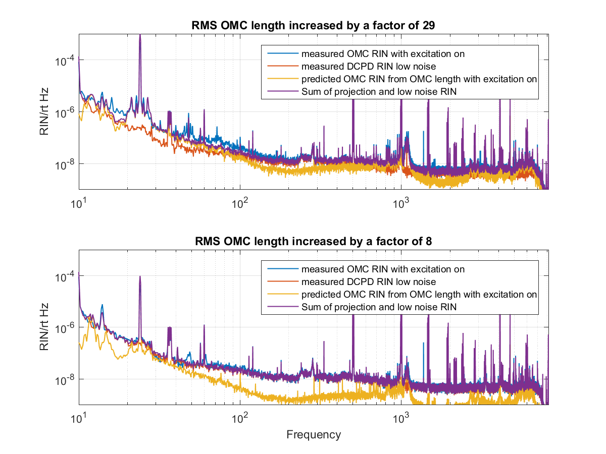
To combine these measurements into one estimate of OMC length noise, I used some time domain filters to choose the frequencies where each measurement is valid. Making time domain filters to combine these signals is a little tricky, I have started with complimentary comlimentary filters to blend the sideband and carrier measurements around 1 kHz, and the sensor noise and residual estimates around 20 Hz, but if you look closely at the combined estimate there are places where it is off by 40% or more from what seems reasonable. The resulting estimates, are shown in the 4th attached png. When there is no excitation, the RMS of 1pm is dominated by the dither line, with a 0.3 count excitation the RMS is 9 pm, and with a 1 count exctation the RMS is 29 pm.
Projections to DARM
With an estimate of the OMC length in the time domain, using the first equation in the attached PDF it can easily be used to predict OMC RIN. The 5th png attached shows DCPD RIN when I did injections with the IFO at low noise. The largest injection (which increased the RMS by a factor of almost 30) caused a braodband increase in noise below about 200 Hz, with peaks at the 2nd, 4th, and 6th harmonics of the injection frquency. The model predicts most of the features of DARM within about a factor of 2, although not the upconversion around the 4th harmonic, and not the upconversion around the 4th harmonic.
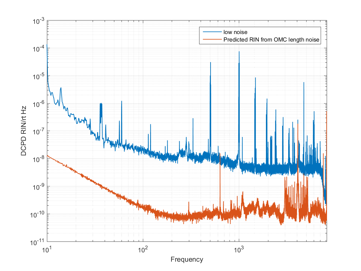
The last png attachment is the prediction for the noise in DARM caused by OMC length without an excitation. It is 2 orders of magnitude below DARM at 100 Hz, the only place OMC length might explain the level of noise in DARM is around the dither frequency.