Following Betsy and Nutsinee's efforts to clean up the alignment of the ITMX_HWS probe beam yesterday, we reinitialized the HWSX code. The code has been running continuously since then. Last night there was a lock-loss in the IFO (at 1173593679) after being locked for about 2 hours.
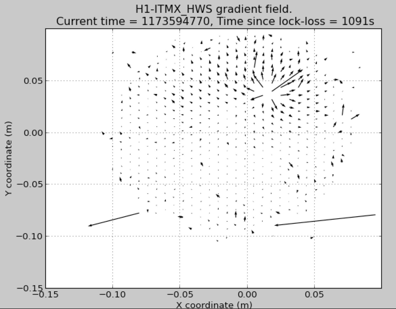
I pulled the HWS gradient field data from that time and have plotted it in the attached movie. I have rezeroed the HWS so that the reference wavefront was taken about 600s before the lock-loss, i.e when the IFO is hot. All subsequent gradient fields are plotted in reference to this initial state.
I then plot the difference in the gradient field from this reference time at intervals of 60s. Therefore, any thermal lenses you see in the gradient field appear as the negative of what would appear during a lock-acquisition (and when the cold state of the IFO is used for a reference wavefront). However, the heat flow is a linear process with regards to the input power, so analyzing the lens decay is fine for determining absorption.
From the point at which the lock-loss occurs:
- what physically happens is that ITMX starts to cool down and any residual thermal lenses start to vanish.
- what we see on the HWS gradient field is a strong negative lens form.
- The lens is about 1cm - 2cm in diameter,
- it seems to form to full size within a minute or two.
- These two features, although qualitative, are very characteristic of a point absorber on the optic.
Notes:
- there are few errant spots out near the edges of the HWS FOV. These are noise - just ignore them. I've not had an opportunity to remove them from the data
- At the time of the lock-loss, you can also see a bulk pitch towards the top left - this represents a tilt change in the optic.
- By and large, the gradient field shows no systematic noise on it, indicating that this measurement is quite clean.

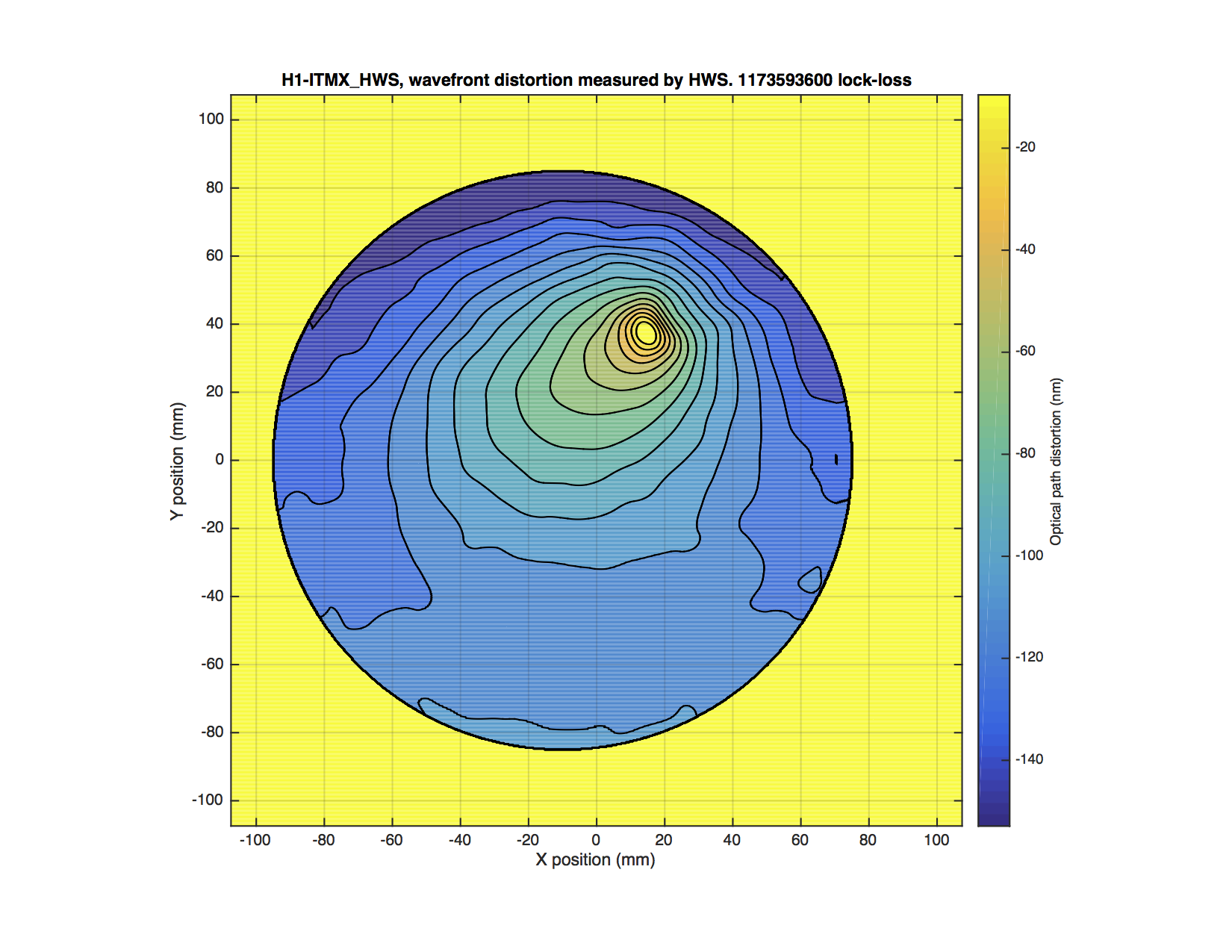
The gradient field is shown above. The numerically integrated wavefront is shown below. There is some residual tilt in this wavefront.
The lens scale is about 60-70nm over a radius of about 20mm.

The next step is to compare this to COMSOL models of thermal lensing for heat sources of different sizes. This is to determine if this data matches a physical model.
Other possible explanations:
So far, I can only come up with one possible other interpretation. If there is excessive 1064nm light leaking onto the HWS, and the HWS doesn't filter it out enough with the bandpass filter (or this isn't in place), this might cause a systematic error in the HWS measurement. We can test to see if we're getting excess contamination of 1064nm light by leaving the HWS code running and turning off the SLED. The HWS code will record images on the HWS camera and when the IFO lock is lost or reacquired, we'll be able to see if there is excess 1064nm light on the CCD in the same position as the apparent thermal lens.
Looks familiar to me -- see the animations at the bottom of 29712.
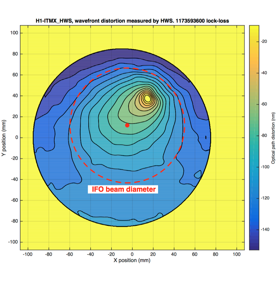
Based on fiducial reference points (baffle edges and earthquake stops) in the image of the ITMX HWS return beam, I estimate that the center of the ITM optic is [-6mm, +9mm] in the HWS coordinate system (as magified up to the ITM).This is illustrated in the attached image.
Orientation: the image is inverted vertically, the top of the optic is at the bottom of the image. We don't have the left-right orientation determined.
Best estimate: the displacement of the point source is about [20mm,25mm] from the optic center - toward the lower part of the optic.
A RH measurement would provide a more precise estimate.

Here is a zoom of the OPD. The tilt has been removed and the contours are labeled (they're every 10nm).


