One of the goals of the OAT was that the residual arm motion measured by the green beam, with the VCO to arm offloading, is about 10 nm or so for f<0.5Hz.
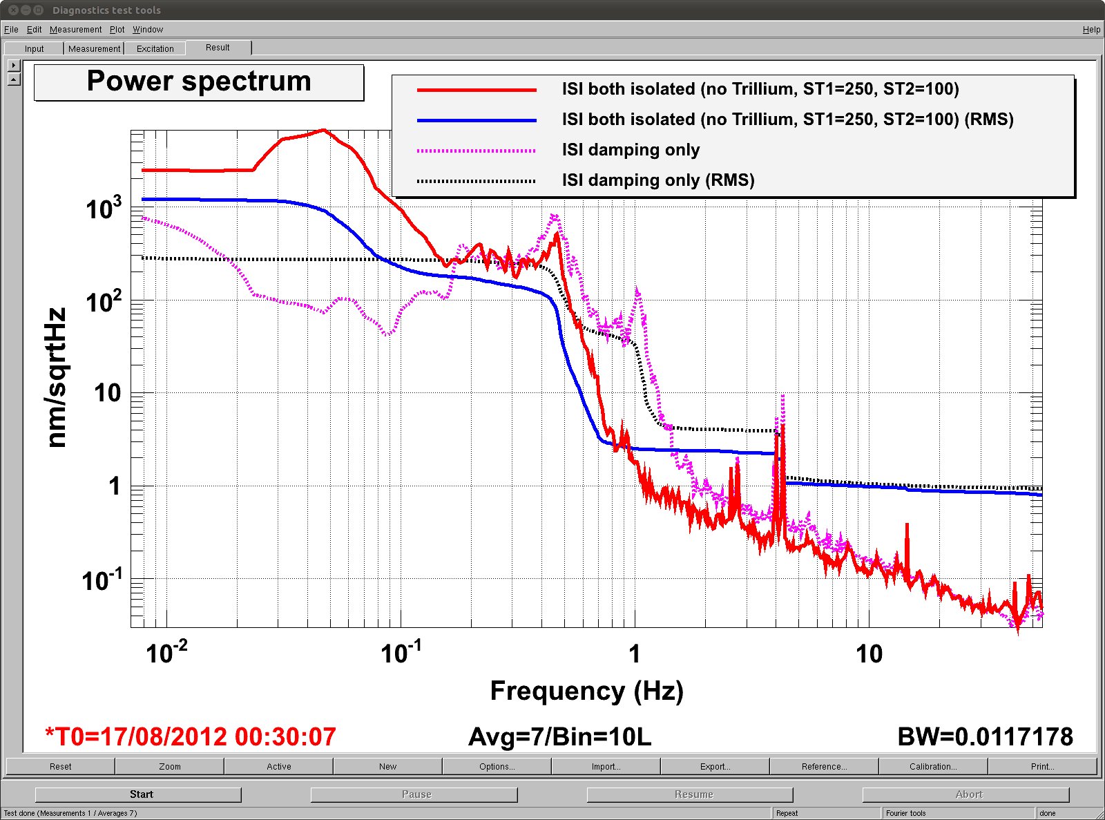
Attached is the calibrated residual motion in nm/sqrtHz. Solid lines are with both ISI isolated (non-aggressive crossover, without Trillium), and the dashed are with both ISI only damped. These are not a true A/B comparison (different lock stretches, different seismic level, only 7 averages) but are good enough to show you some ball park numbers.
1. Even though the isolation helps greatly at 1Hz, it makes a huge peak at about 40 to 50 mHz with the RMS of about a micro meter. This might or might not be larger than expected, but as I understand from Vincent we expect some amplification at this frequency.
2. With or without the isolation, 0.46Hz peak is also big. Isolation might be helping a factor of 2 or so but we need a factor of 20 or more.
3. Though it's outside the scope of the stated OAT goal, 1Hz peak is not negligible. Without isolation, this should be reduced by a factor of at least 5 or so.
Vincent might be able to refine ISI further, but we shouldn't expect HEPI/ISI alone to bring the residual RMS down to 10nm level (or even 50nm for that matter, stated goal of OAT for HEPI/ISI is 200nm RMS and we're already quite close).
Regardless of the ISI isolation, we need a more aggressive VCO offloading to the length. Right now VCO is only offloaded to the HEPI, and the UGF of this path is smaller than 10 mHz. We need to use another path to the ETM and/or ITM suspension if we want a larger UGF to suppress e.g. 0.46Hz peak.
The reason why no work has been done for this for a long time, I think, is because there was a huge POS to PIT coupling when you drive M0. What's the current status of drive diagonalization (don't confuse this with sensing diagonalization)?
Message received by team SUS. We'll think on it.
The latest measurement of the ETMy M0 Diagonalization was earlier this year on May 21st.  The attached PDF contains the M0 Vertical and Yaw DoF diagonalization measurement results.  The motivation behind the measurements was to drive the OSEM coils at a single frequency within the resonance band for the Vertical and Yaw DoFs and measure the transfer function between this drive and the individual OSEMs.  The desired result was to have the individual OSEMs not contributing to the drive signal have a response at least 15dB lower than the driving OSEMs.

The Yaw DoF was driven at 1.3Hz with a 25-ct amplitude. The Yaw DoF is comprised of the M0-F2 and M0-F3 OSEMs. The response of the remaining OSEMs (M0-F1, LF, RT, SD) was at least 28dB lower than the drive signals.

The Vertical DoF was driven at 2.2Hz with a 1000-ct amplitude.  The M0-LF and M0-RT OSEMs constitute the Vertical DoF.  The response of the other OSEMs was at least 23dB isolated from the driving OSEMs.
