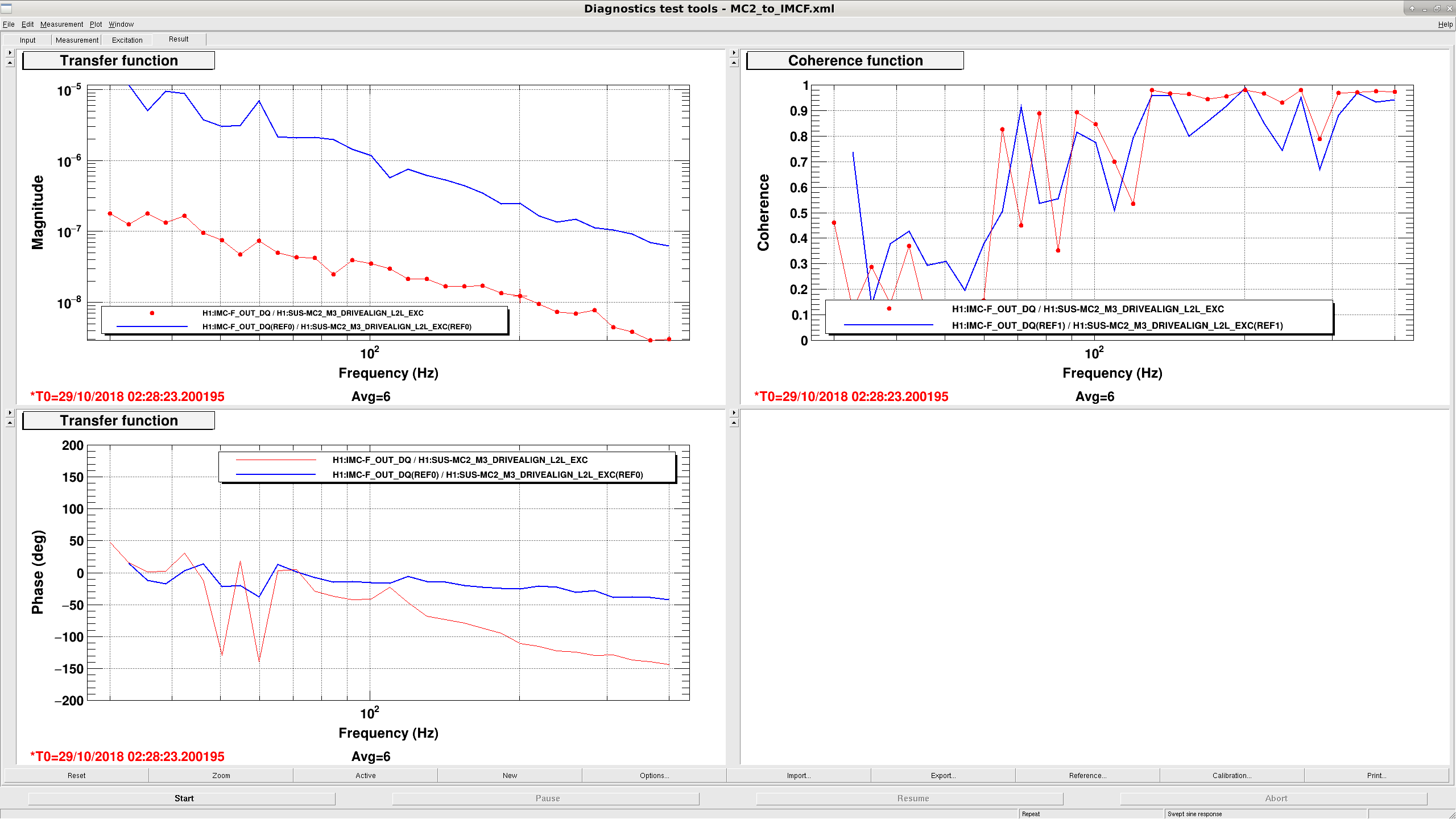
Previously when trying to understand the CARM loop, I'd calibrated to some additive noise on the input to the interferometer.  There were also some issues with our understanding of the REFL_SERVO_ERR channel and our frequency injection into MC2 that were not resolved.

Here, I will calibrate the CARM error signal into the loop-suppressed frequency input into the IFO, and resolve some of the misunderstandings with REFL_SERVO_ERR and the MC2 frequency injection calibration.

REFL_SERVO_ERR and the shot noise spectra
It's as simple as we didn't know there was a factor of 200 boost in the "generic filter" part of the CM board which goes to the ADC.  So to convert from common mode board volts to counts you have to multiply by 200 V/V and 2**16/40 cts/V.
PDF 1 shows the REFL_SERVO_ERR channel plotted alongside analog spectra for REFL9 shot noise and dark noise spectra.  The dark noise spectra were taken without the mode cleaner locked, while the shot noise was taken with direct reflection off PRM with the rest of the IFO misaligned and 2 watts input.

MC2 Length Injection to Frequency Calibration
While CARM was locked, Rana and I drove MC2 in length and got a TF from REFL_SERVO_ERR [cts] to IMC_F [kHz] of 3.1e-7 kHz/cts at 71.1 Hz to calibrate CARM last time.  That's valid as long as you remember that CARM is not doing all the work: you have to include the suppression of the IMC as well, which I did not previously.
To account for this, we measure the TF from MC2 drive [cts] to IMC_F while the IMC is locked by itself, then again while CARM is locked.  This gives us PNG 1, with a higher suppression by a factor of 20.7 for CARM locked vs. IMC alone at around 100 Hz.
What this means for our calibration of CARM is we have to multiply the REFL_SERVO_ERR to IMC_F TF by 20.7 to get exactly how much work CARM was doing trying to suppress the MC2 drive.

Now, given our transimpedance of 2900 V/W, 2dB sum node gain, and CARM pole of 0.6 Hz, we can calculate the CARM optical gain at DC: (1/3.1e-7 cts/kHz)(40/2**16 V/cts)(1/200 V/V)(1/2dB V/V)(1/2900 W/V) * abs(1+1j*71.1/0.6)  ~ 4 mW/Hz CARM optical gain.

CARM Error Spectrum
To calibrate the CARM error spectrum into incident IFO noise, I divide by the CARM boost (zero 4kHz, pole 40 Hz), sum node gain, and CARM plant that I just calculated.  This simply removes the CARM pole from the laser.
I also calculated the shot noise for 8.6 mW on the REFL9 PD we see when we are locked at NOMINAL_LOW_NOISE with 22 watts input.  Seems like we are sensing noise limited from around 10 Hz to 500 Hz.

I'm sort of confused by the MC2 injection description. I would instead say that the IMC loop makes the laser follow the MC2 motion exactly (since the gain is > 100 for all frequencies we care about). So then we can calibrate the MC2 drive directly into Hz.
To then measure the CARM to DARM coupling, we drive MC2 and measure the TF to the CM board error point. This signal will be MC2/(1 + G_CM). Since we know G_CM exactly from our CM model which was fit to the measurement, we have no need to know about the CARM plant or optical gain.
For the estimating of the CARM noise budget, I think instead of just shot noise, you should include the measured noise with only the PRM aligned. This will then include the scattering noise in REFL in addition to the shot noise.
As a 3rd step, you should drive PRCL and measure CARM. The PRCL noise gets injected into CARM and shows up as an extra sensing noise since we have no PRCLFF->CARM path.