craig.cahillane@LIGO.ORG - posted 14:29, Tuesday 08 January 2019 - last comment - 22:48, Tuesday 08 January 2019(46276)
What is the arm power?
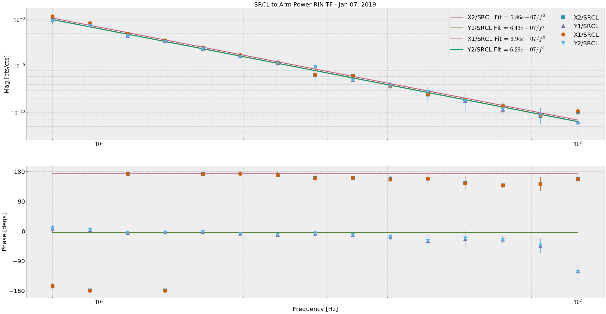
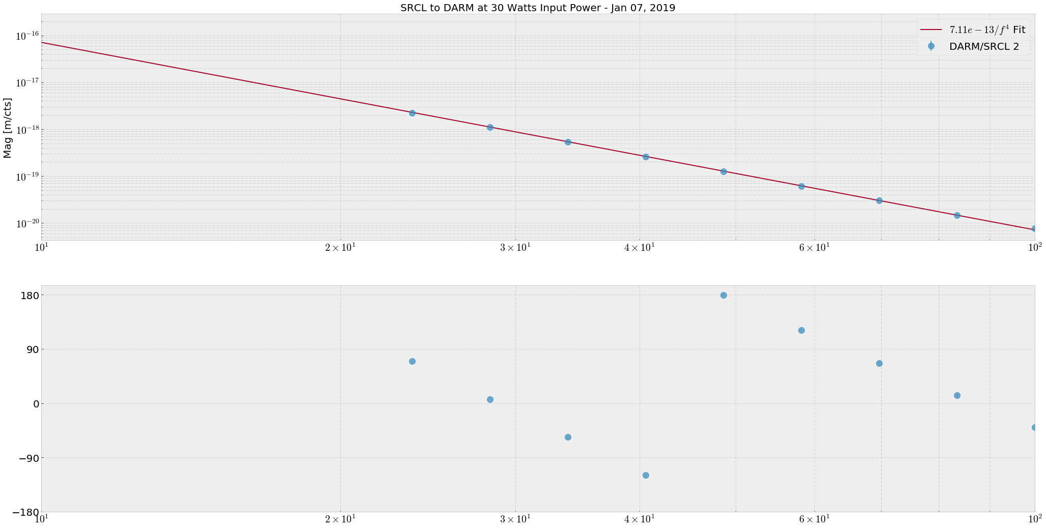
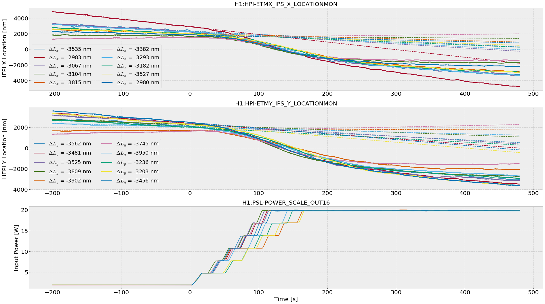
For 30 watts of input power:Arm Power = 127.2 +- 5.4 kWSRCL Dither to Arm Power Measurement: Long ago, Peter F came to Hanford and asked me to measure the arm power by moving the SRM. The idea is to use the SRCL dither to cause the arm power to fluctuate differentially. When the arm power fluctuates differentially, arm radiation pressure couples to DARM. I measured the TF from SRCL to arm power transmissions RIN and SRCL to DARM at 30 watts of input power and 43 power recycling gain and SRCL feedforward off. (Had to divide the DARM calibration by two because our DARM is calibrated such that LDARM = Lx - Ly, but I assumed LDARM = (Lx - Ly)/2. This was particularly hard to find.) I then fit some constants α1 and α2 to the TFs: α2/f^2 to the SRCL_ctrl/ArmPowerTransRIN measurements and α1/f^4 to the SRCL_ctrl/DARM, and recovered arm power via the equationParm = α1/α2 * π2 * mq * cwhere mq is the mass of the ITMs/ETMs. See the attached PDF for a more exposition to the above equation. In the future we can just take the TF from Arm Power Transmission RIN to DARM. Results:α1 = 7.11 +- 0.07 × 10⁻¹³ (Attachment 2) α2 = 6.6 +- 0.3 × 10⁻⁷ (Attachment 1)From this measurement we can back out an approximate arm power gain. The power in the arms is given by Parm = Pin * gP2 * garm2 / 2 where gP2 ≈ 43 is the power recycling gain and garm2 is the arm power gain. In a perfect, lossless world we would have garm2 = 282. In reality, we have garm2 ≈ 197 EDIT: Gabriele comments that for this low of an arm gain, our losses would have to be incredibly high, on the order of 5000 ppm. EDIT: Stefan asked about the SRCL to Arm RIN fit differences between the arms. There are two QPDs (A and B) at the ends of both arms. Names are like H1:ASC-{X,Y}_TR_{A,B}_NSUM_OUT. These QPD sums are used for monitoring the arm powers. In Attachment 1, I refer to H1:ASC-X_TR_A_NSUM_OUT as X1, H1:ASC-X_TR_B_NSUM_OUT as X2, etc... In the legend, we can see the individual fit values to each ArmTransRIN/SRCL TF to a α2/f2 model. Each of these fits were made with a MCMC and had an uncertainty of around 0.8%QPD/SRCLctrl TFs Model Value X1 X2 Y1 Y2 ---------------------------------------------------------------------------- α2 6.94 × 10⁻⁷ 6.86 × 10⁻⁷ 6.43 × 10⁻⁷ 6.29 × 10⁻⁷We can see that the X1 and X2 fits are close (within 0.6%), and Y1 and Y2 fits are close (within 1%), but the X and Y arm fits together are slightly different (within 4%). Looking at the PDF attached, we can say that the optical response of the Y arm to the SRCL dither γ is less than the optical response of the X arm. ----------------------------------------------------------------------------------------------------------------------------------------------------------------------------------------------------------------- HEPI Offloading Measurement:Results: Change in HEPI offload for each arm during 2 to 20 watt powerup: (see Attachment 3) ΔHEPI_X = -3287 +- 261 nm (or +-8%) ΔHEPI_Y = -3587 +- 246 nm (or +-7%) Change in X Arm Power from 2 to 20 W Input = 95 +- 8 kW Change in Y Arm Power from 2 to 20 W Input = 104 +- 7 kW Total X Arm Power at 20 W = 105 +- 8 kW Total Y Arm Power at 20 W = 115 +- 8 kW Estimated X Arm Power at 30 W = 158 +- 13 kW Estimated Y Arm Power at 30 W = 173 +- 12 kW Arm Power Ratio = Px/Py = 0.9 +- 0.1As a double check of this arm power measurement I have been looking at HEPI offloading of tidal during INCREASE_POWER. When the input power increases from 2 to 20 watts, HEPI moves due to the increase of radiation pressure by about 3000 nanometers in each arm. I fit a simple trend line to capture what the tidal servo was doing anyway, then subtract it at after around 400 seconds when the offload is complete, for 10 separate INCREASE_POWERs. (Attachment 3) We can use these results to estimate the arm powers, assuming all other things being equal in LSC->HEPI tidal offloading, and ΔHEPI_X = ΔLXarm:HEPI Analysis ΔPx = ΔHEPI_X * c/(4 k), where k = DC compliance of the quad TST stage = 2.6 × 10⁻³ m/N. If we trust the measured PRG of ~46 for each of these powerups, that would correspond to an arm gain of gXarm2 ≈ 230 gYarm2 ≈ 250So this measurement reports much higher arm powers, but also a huge mismatch between arms (> 10%). We can learn a lot more about the IFO from this measurement and others like it. The end goal of this is to understand noise couplings to DARM, many of which are governed by these hard to measure numbers like arm power, power recycling gain, signal recycling gain, SRCL detuning and optical spring, DARM offset, coupled cavity poles, etc. If we can make a more complete picture of the IFO, hopefully we will find some things that don't add up. EDITTED for clarity of which measurement gave me which information, added the arm power calculations from HEPI offloading done with Sheila, and added comments from Stefan and Gabriele.
Images attached to this report
Non-image files attached to this report

Comments related to this report
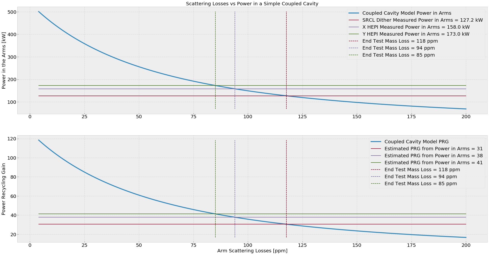
Stefan and I looked at a simple coupled cavity response to arm scattering losses to see what PRGs are consistent with the above arm power levels. We modeled the scattering losses as excess ETM transmission. For the coupled cavity, we foundP_arm = P_in * g_ccArm2 / 2 where g_ccArm = tP tI / (1 + rP rI - rP rE - rI rE) and rP = amplitude reflectivity of the PRM rI = amplitude reflectivity of the ITM rE = amplitude reflectivity of the ETM tP = amplitude transmission of the PRM = sqrt(0.03) tI = amplitude transmission of the ITM = sqrt(0.014) tE = amplitude transmission of the ETM = sqrt(4ppm) (nominal)By varying the ETM transmission from it's nominal 4 ppm, we found arm losses that gave the arm power levels found for 30 watt input above, and then looked at what the PRG would be for that level of losses.Meas Arm Power [kW] Arm Losses [ppm] PRG SRCL dither 127.3 118 31 HEPI X 158. 94 38 HEPI Y 173. 85 41It seems that the SRCL dither measurement arm power is not consistent with the reported PRG of 43 we have at Hanford with 30 watts input.
Images attached to this comment